Review

Joining of Fibre-Reinforced Thermoplastic Polymer Composites by Friction Stir Welding—A Review

1
Department of Mechanical Engineering, CEMMPRE, University of Coimbra, 3030-788 Coimbra, Portugal
2
ISEL, Departamento de Engenharia Mecânica, Instituto Politécnico de Lisboa, Rua Conselheiro Emídio Navarro 1, 1959-007 Lisbon, Portugal
3
LIDA-ESAD.CR, Instituto Politécnico de Leiria, Rua Isidoro Inácio Alves de Carvalho, 2500-321 Caldas da Rainha, Portugal
*
Author to whom correspondence should be addressed.
Appl. Sci. 2022, 12(5), 2744; https://doi.org/10.3390/app12052744
Submission received: 31 January 2022 / Revised: 1 March 2022 / Accepted: 3 March 2022 / Published: 7 March 2022
(This article belongs to the Special Issue Fracture Mechanics and Structural Integrity of Composite Materials)

Abstract

:
The objective of the current work is to show the potential of the friction stir welding (FSW) and its variants to join fibre-reinforced thermoplastic polymer (FRTP) composites. To accomplish that, the FSW technique and two other important variants, the friction stir spot welding (FSSW) and the refill friction stir spot welding (RFSSW), are presented and explained in a brief but complete way. Since the joining of FRTP composites by FSSW has not yet been demonstrated, the literature review will be focused on the FSW and RFSSW techniques. In each review, the welding conditions and parameters studied by the different authors are presented and discussed, as well as the most important conclusions taken from them. About FSW, it can be concluded that the rotational speed and the welding speed have great influence on heat generation, mixture quality, and fibre fragmentation degree, while the tilt angle only has residual influence on the process. The reduction of internal and external defects can be achieved by adjusting axial force and plunge depth. Threaded or grooved conical pins achieved better results than other geometries. Stationary shoulder tools showed better performance than conventional tools. Regarding the RFSSW, it has not yet been possible to deepen conclusions about most of the welding parameters, but its feasibility is demonstrated.

1. Introduction

The number of applications of the fibre-reinforced polymer (FRP) composites has been growing solidly as they are high performance materials that can be manufactured quickly and with low production costs [1]. Fibre-reinforced thermoplastic polymer (FRTP) composites have less sensitivity to damage when loaded statically or dynamically, and have greater potential for repair than composites of thermosetting matrix [2]. FRTP composites present good mechanical properties, low density, good resistance to chemicals, are recyclable and, theoretically, have infinite life in service [3]. Compared to common metallic materials, FRTP composites present superior specific strength and specific stiffness [4]. These materials are mostly intended for the application in the automotive, naval, aeronautic, and aerospace industries [5], as they allow the production of lightweight structures with high mechanical performance. Thus, their inclusion contributes to the reduction of fuel consumption and CO2 emissions [6]. The two most common reinforcements used for the production of these composites are the glass fibre (GF) and the carbon fibre (CF) [3].
The conventional methods used to join FRTP composites are the mechanical fastening and the adhesive bonding [7]. Because mechanical joints can be non-permanent, they are very interesting for disassembly or maintenance purposes. However, mechanical fastening is normally associated with the addition of mass and may require the existence of holes in the parts to be joined, which leads to high stress concentration and to composite damage, due to the interruption of the reinforcement fibres [7]. In addition, the majority of the mechanical joints are not watertight [8]. Contrary to mechanical fastening, the adhesive bonding only induces residual stress concentration. On the other hand, the adhesive bonding can be difficult to perform on FRTP composites [7], due to the reduced surface tension of these materials. This joining method requires joint preparation and a cure period. The cure period varies between a few seconds and many hours, it may require the application of heat and/or pressure, and it is normally associated with the emission of toxic fumes [9]. Fatigue stresses in an aqueous environment promote a faster degradation of the adhesives [10].
Since welding appears to have great potential to join FRTP composites, several welding technologies have been developed and tested in recent years. In addition to friction stir welding (FSW), ultrasonic welding (USW), laser welding (LW), and induction welding (IW) stand out. The USW allows joints with good mechanical strength if the fibres are not cut. However, the application is limited to reduced thicknesses. LW has been extensively investigated, as it is a fast and flexible process, and does not require direct contact between tools and joint. On the other hand, LW depends a lot on the optical properties of the materials and currently gives rise to the formation of porosity in the composite, caused by gases and the shrinkage of the molten polymer, which reduces the strength of the joints. In turn, IW requires long process times, presents difficulties related to heat distribution uniformity, and is not recommended to join large parts [7].
FSW is a joining technique that was developed in the British engineering organization The Welding Institute and was patented by Thomas et al. in 1991 [11,12]. This process emerged with the goal of overcoming the difficulties of conventional welding techniques, when applied to lightweight alloys. Since the success of welding aluminium alloys has been demonstrated, FSW has been used in the welding of many other metals and their alloys, such as magnesium, titanium, copper, and steel [13]. FSW can additionally be used to join dissimilar metals [14,15,16]. Nevertheless, FSW is not a welding technique exclusive for the joining of metallic materials, as its application for the joining of polymers and polymeric matrix composites, for example, has already been demonstrated. Recently, FSW is also being studied for the joining of polymers and FRTP composites to metals [17,18,19,20].
The feasibility of joining unreinforced polymers by FSW was demonstrated in 1997 [21,22]. This welding technique is only suitable for thermoplastics and not for thermosetting polymers. While thermoplastics increase their fluidity when exposed to an increase of temperature, and can be moulded at temperatures below the degradation point, the thermosets do not [23]. The literature shows that it is already possible to join several thermoplastics by FSW, such as acrylonitrile butadiene styrene (ABS) [24,25,26,27], polyamide 6 and 66 (PA6 and PA66) [28,29,30], polycarbonate (PC) [31,32], polyethylene (PE) [33,34,35], polylactic acid (PLA) [36], polymethylmethacrylate (PMMA) [37,38,39], polyphenylene sulfide (PPS) [40], polypropylene (PP) [41,42,43], and polyvinyl chloride (PVC) [44]. Since 2011, FSW is also being studied for the joining of FRTP composites reinforced with chopped fibres [45,46]. Most of the publications found are related to PP reinforced with chopped GF [3,5,45,46,47,48] or chopped CF [3,5,48,49], but matrices of PA6 [50,51,52,53], PC [54] and polyetheretherketone (PEEK) [40] have also been reported. The studies found in the literature are still very much focused on the feasibility of the technology. Even so, Meyer et al. [51] and Eslami et al. [52] obtained joint efficiencies of about 50% and 59%, respectively, both for the joining of PA6 reinforced with 30% of GF. These results show that the technology has a lot of potential. Thus, it is expected that with future studies on the optimization of the technology, it will be possible to obtain even better joint efficiencies.
Within FSW of polymeric base materials, it is worth mentioning friction stir spot welding (FSSW) and refill friction stir spot welding (RFSSW) [55], which are variants of the conventional FSW technique that can be distinguished by the absence of linear movement of the tool. Although they only allow punctual joining, which results in stress concentration and does not guarantee watertight welds, they must be considered as promising welding techniques as well.
FSSW of unreinforced polymers was demonstrated in 2008 when Arici and Mert [56] reported the success of lap joining PP plates. Since then, FSSW has been studied to join ABS [57,58], PC [59,60,61], PE [62,63,64], and PMMA [65]. Regarding FSSW of FRTP composites, no publications were found.
The feasibility of the joining of unreinforced polymers by RFSSW was demonstrated by Oliveira et al. [66] in 2010, who successfully welded PMMA plates. The dissimilar joining of unreinforced polymers and FRTP composites by RFSSW was reported in 2014 by Gonçalves et al. [67,68]. One year later, by successfully joining CF reinforced PA66 laminate plates, Gonçalves et al. [69] demonstrated the joining of FRTP composites by RFSSW. It is important to highlight the fact that this was the first publication found that referred to the joining of FRTP composites reinforced with continuous fibres in the literature.
The objective of the current work is to show the potential of the FSW and its variants to join FRTP composites. To accomplish that, the FSW technique and two other important variants, the FSSW and the RFSSW, are presented and explained in a brief but complete way. Despite not having found any publication referring the joining of FRTP composites by FSSW, it is to be expected that in the near future this topic will be deeply investigated. Therefore, the FSSW technique will be shortly presented. Another reason that justifies the need to present the FSSW technique is that it helps to understand and distinguish the RFSSW technique.
The FSW review is focused on polymers reinforced with chopped fibres, as no publications on continuous reinforcements were found. Still, Yousefpour et al. [7] defends that the FSW of FRTP composites of continuous reinforcements requires further investigation. The great potential for joining FRTP composites of discontinuous reinforcements was already proven, as will be presented.
Regarding the joining of the FRTP composite materials by RFSSW, a couple of publications were found [69,70]. These will be presented and discussed. Although the information is still limited, with only two publications found, it was decided to include it on this review, as it is the only technique reported among FSW and FSW variants that addresses the joining of FRTP composites reinforced with continuous fibres. Since these are the first publications on the subject, they are focused on the feasibility of the technology. Although all parameters are clearly presented, there is not enough information to draw good conclusions about the influence of some of them. However, the results obtained show that the technique was applied with success and that it has a lot of potential. Therefore, it was considered as important for this review.
The next three chapters seek to present and explain in a brief but complete way the FSW, FSSW, and RFSSW techniques. The welding procedures and the different parameters involved are explained. In the two following chapters, studies related to the joining of FRTP composites by FSW and RFSSW will be presented. In these two chapters, the welding conditions and parameters used in each study will be presented and discussed, as well as the main conclusions pointed by the different authors. In this way, it is expected that the in-depth study of FSW and its variants will allow a better understanding of the current potential and limitations of these processes to join FRTP composites. It is important to highlight that this is not the first review approaching the joining of FRTP composites by FSW. The publications of Eslami et al. [71], Huang et al. [72], Kumar et al. [73], and Iftikhar et al. [74] complement the current work and, therefore, are recommended. On the other hand, based on the literature found, the current work is the first only focused on this subject.

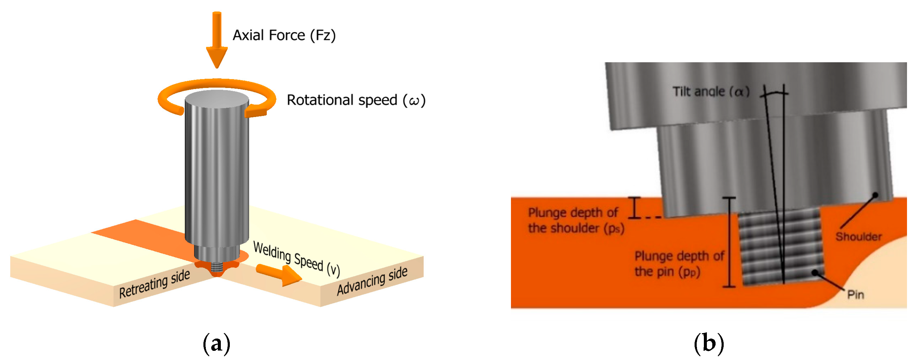
2. Friction Stir Welding (FSW)

FSW involves the conversion of mechanical energy into thermal energy [3]. The conventional welding tool is composed of two fundamental non-consumable elements, which are the shoulder and the pin [75]. The pin is also known as probe. In FSW with conventional tool, the shoulder and the pin rotate together, being both responsible for generating enough frictional heat to soften the materials. The pin is also responsible for mixing the softened material, while the shoulder avoids its projection out of the welding zone [76]. Figure 1 illustrates the FSW process with a conventional tool and some of the main welding parameters.
FSW is a simple process that follows a set of four well-defined stages, which are schematically shown in Figure 2. The first stage consists of the progressive penetration of the rotating tool into the material, until it reaches the desired depth. This first stage is known as the plunging stage. Then, there is a waiting step in which the tool remains in rotation without advancing, so that the material reaches the ideal operation temperature. This step is called the dwell stage and its duration is defined as the dwell time. In the third stage, called the welding stage, the translation movement of the tool occurs, giving rise to the joining of the plates after cooling the material. When the tool reaches the end of the defined path, the rotation and the translation movement stop. The last step is called the end of welding and tool retracting stage [76,77]. After completing all the steps of the FSW process, the material must remain clamped to the structure for a few minutes to decrease the possibilities of distortions during cooling [33]. Some authors defend the need of a fifth step, the cooling stage, since the cooling conditions may affect the quality of the weld produced [78]. The welded joint usually presents a keyhole at the end of the welding path and material protrusion at the beginning [75]. Generally, the peak forces of the FSW process occur during the plunging stage, as the materials have not yet reached the operating temperatures [79,80,81].
FSW does not require the addition of material, protective atmosphere, or joint preparation [12]. Since during the process there are no emissions of toxic fumes or UV radiation, it can be said that this welding technique is safer and environmentally friendlier than many others [46]. Because the main source of heat of the FSW process is the friction between the base material and the rotating tool, this welding process can be classified as an economic and energy-efficient process compared to others that traditionally consume higher energy levels [82]. Even for large thickness, welding can be carried out with a single pass of the tool and the welds do not require any posttreatment. Serial production can be carried out using robots [45]. Despite being common to find voids and cavities within the weld seam, as a consequence of improper mixing and entrapped air, for example, these voids are not interconnected, meaning that the joint is normally watertight [45]. FSW allows the production of 3D complex structures [25] and can be applied to any joint configuration, although the most common is to weld in butt or lap joint configurations [26]. When FSW is performed in lap joint configuration, it is also known as friction stir lap welding (FSLW) [27].
Generally, the main source of heat during the FSW process is friction. The consequent plastic deformation of the material also contributes to the increase of the total amount of heat generated, but with much less impact than the heat produced by friction [75]. Some FSW techniques require the addition of external heat, which can be done by heating the materials and/or the welding tools. Other FSW techniques use tools with stationary shoulders, where the pin is the only element generating frictional heat. A review work performed by Pereira et al. [83] regarding the effect of the FSW techniques and parameters on polymer joint efficiency demonstrated that for welding unreinforced polymers, the stationary shoulder tools with the addition of external heat produce stronger joints, with better surface appearance and fewer defects. The comparison between conventional and stationary-shoulder tools has already been evaluated for FRTP composites. On the other hand, the influence of the addition of external heat on FSW performance for these materials has not yet been reported in the literature.

FSW Main Welding Parameters

Despite the simplicity of operation, the number of parameters involved that affect the quality of the welds makes the study of the FSW complex. For this reason, it is important to explain what each parameter corresponds to, in order to understand its influence on the process. The main welding parameters involved in the FSW are the rotational speed ( ω ) , welding speed ( v ) , tilt angle ( α ) , plunge depth ( p ) , and axial force ( F z ) .
The rotational speed ( ω ) quantifies the amount of rotation of the welding tool and it is measured in rotations per minute [rpm]. The welding speed ( v ) , also known as feed rate, traverse speed, and joining speed, corresponds to the velocity of the linear movement of the welding tool along the joint and it is normally measured in millimetres per minute [mm/min]. The tilt angle ( α ) , or attack angle, corresponds to the inclination of the tool in relation to the normal vector on the material surface, and it is measured on degrees [°]. The plunge depth ( p ) , or penetration depth, quantifies the penetration of the tool on the material and is measured in millimetres [mm]. Finally, the axial force ( F z ) is the welding parameter that is used to measure the force exerted by the tool on the material during the welding process and is quantified in Newtons [N]. According to Mendes et al. (2014) [26], the axial pressure ( P a ) is a parameter that has more representativity than axial force. However, the choice of evaluating force instead of pressure is related to the fact that the FSW equipment is usually parameterized by force.
Regarding the plunge depth parameter, two different procedures are used to measure the penetration of the tool into the material, which results in different values being determined. Therefore, it is important to distinguish the plunge depth of the shoulder ( p s ) and the plunge depth of the pin ( p p ) . The first is the maximum depth reached by the shoulder relative to the surface of the material, while the second is the maximum depth reached by the pin relative to the surface of the material. Figure 1b shows the two measurement procedures, thus allowing to clarify why the values obtained are different, although both are measuring the penetration of the tool.
The dimension and geometry of the tool components also influence the quality of the welds. Therefore, they must be considered important parameters as well. Because most of the shoulders are circular, especially in the FSW with rotary shoulder tools, where the shoulder contributes to the total amount of frictional heat generated, the influence of the shoulder diameter ( d s ) must be considered. However, in the case of FSW with stationary shoulder tools it is also common to use rectangular shoulders. Therefore, depending on the case, instead of the diameter of the shoulder, the length and width of this component should be considered. Furthermore, the pin length ( l p ) and the pin diameter ( d p ) are the other two important welding parameters. The pin length must be chosen depending on the thickness of the materials [7]. In terms of pin geometry ( G p ) , the geometries are normally cylindrical, tapered, or prismatic. The side surfaces of the pins can be straight, or contain irregularities, such as threads or grooves. These features are shown in Figure 3.
With the development of the technology, new FSW variants have emerged. Some of them require the addition of external heat to the welding process, as mentioned before. Therefore, it became necessary to consider the tool temperature ( T t ) and the material temperature ( T m ) as important parameters for the characterization of the FSW process.
The dwell time ( t D ) , also known as holding time, is another parameter that must be considered, but that it is often undervalued. It refers to the time between the moment that the tool reaches the desired plunge depth and the beginning of the translation movement. The dwell time controls the preheating of the materials before the actual welding. Poor calibration of this parameter severely affects the quality of the beginning of the weld seam. Short dwell times lead to the formation of weak joints due to the lack of heat generated. On the other hand, in the case of polymer-based materials, excessively long dwell times promote material degradation [33].
Through the macro and micro analysis of the cross section of the welds, it is noticed that the right and left sides consistently present different characteristics. The side of the material where the direction of the rotational speed is the same as the traverse movement of the tool is called the advancing side (AS). The side of the weld on which the direction of the rotational speed is opposite to the traverse movement of the tool is called the retreating side (RS) [84], as can be observed in Figure 1a. When welding polymeric base materials, most of the welding defects, such as voids and cracks, preferably occur on the RS [50,51]. The dissimilar distribution of the heat generated, which is higher in the AS, makes the transportation of the material from the AS to the RS more difficult, preventing a good adhesion of the molten material to the base material on the RS [51]. As a result, most of the welds tend to fail on the RS.
As mentioned before, FSW was initially developed for welding metallic materials such as aluminium and its alloys, which are normally difficult to weld by conventional welding methods [11,12]. Normally, in the FSW process, the metallic materials do not achieve the melting temperature. Therefore, the welding process occurs with the metals in the solid state. This means that the formation of cracks and voids can be avoided, the thermal distortion of the metal after welding is significantly reduced, and the dimensional stability is improved. On the other hand, there is no consensus on the part of the authors regarding the state of the material during the FSW process for polymeric base materials. Inaniwa et al. [44] monitored the pin temperature while welding PE, PA6, and PVC, and concluded that the welding process occurred with the material in the solid state, because the temperature measured was always below the melting temperature of these polymers. However, Strand [9] argued that FSW for polymers is not a process that occurs exclusively in the solid state. According to this author, FSW for polymeric materials is a welding process in which there are portions of solid material suspended in a molten polymeric matrix. Most of the latest publications refer that FSW of polymeric materials occurs exclusively in liquid state. Rezgui et al. [85] and Eslami et al. [86] confirmed this thesis after verifying that most of the temperatures measured during the welding process of PE were above the melting point. In the case of composite welding, Ishraq et al. [54] argued that the process must generate enough temperature to reach the melting of the composite to produce welds with good mechanical properties. On the other hand, excessive temperatures should be avoided as they can lead to the burning and deterioration of the composite materials, resulting in loss of mechanical strength [50,54]. Thus, it is important to control the welding temperature, since it is proved that the joint strength is reduced when the decomposition point is exceeded [20].
The study of the FSSW and the RFSSW involves most of the main FSW parameters, such as rotational speed, plunge depth, dwell time, and axial force/pressure. However, the dwell time definition for the FSSW and RFSSW is different because there is no translation movement. Therefore, the dwell time ends up corresponding to the welding time. In the RFSSW, the term joining time is normally used instead of dwell time. The absence of translation movement of the welding tool in FSSW and RFSSW means that the welding speed is not a parameter to be considered in these welding techniques.

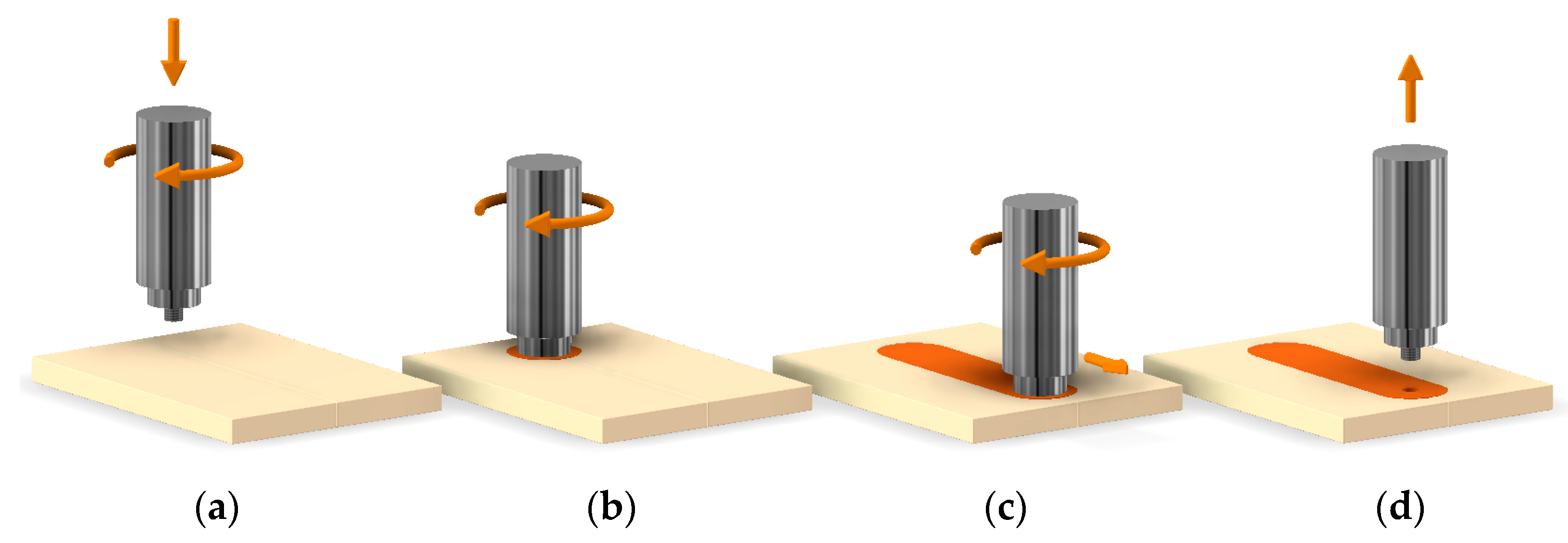
3. Friction Stir Spot Welding (FSSW)

FSSW, also known as friction spot joining (FSJ), is a variant of FSW that is distinguished, mainly by the absence of translation movement [56] and, therefore, is associated with spot welding [60]. Developed by Mazda Motor Corporation and Kawasaki Heavy Industry, FSSW started to be implemented in the automotive industry to replace the traditional resistance welding of aluminium sheets [87], allowing a 40% reduction in equipment investment and a 99% reduction of energy costs [63]. The FSSW is mostly used in lap joint configurations.
FSSW can be divided into three main stages, which are normally called plunging stage, stirring stage, and retraction stage [88], as illustrated in Figure 4. FSSW process starts at the plunging stage, with the penetration of the rotating tool in the material until it reaches the desired plunge depth [56]. The plunge rate must be controlled as the speed of this step influences the success of the entire process [87]. Upon reaching the desired depth, the first stage ends and the stirring stage begins. [64]. During the stirring stage, due to the frictional heat generation created by the high speed of the tool, the material to be joined softens. The rotational movement of the tool is also responsible for mixing the softened material [64]. Normally the stirring stage ends with the stop of the rotation motion, with the tool still in the weld. After a delay time exerting pressure on the material, the retraction stage occurs with the removal of the tool [87]. Removing the tool gives rise to the characteristic hole in the centre of the joint, due to the cooling of the material around the pin [64]. Although this is the most commonly reported procedure, especially in publications on FSSW of polymer-based materials, tool removal can be performed without stopping its rotation. Some authors refer to the existence of an initial preheating phase. However, the experimental results on unreinforced polymers showed that this step has virtually no influence on the welding quality [59,60].
From the analysis of the cross section of the weld region, it is possible to identify two geometric characteristics of the weld that make it possible to draw several conclusions about the quality of the FSSW: the thickness of the weld nugget ( x ) and the thickness of the upper sheet under the shoulder indentation ( y ) [64], both represented in Figure 5. The thickness of the weld nugget ( x ) is directly related to the area of the weld cross section ( A s ). Therefore, the increase in one means the increase in the other. A larger welded area corresponds to a greater amount of joined material and therefore usually means a stronger joint [64]. The thickness of the upper sheet under the shoulder indentation ( y ), as the name implies, corresponds to the height of the upper plate after the FSSW process. This measure is important because the penetration of the shoulder into the upper plate leads to a decrease in its thickness. So, the reduction of this dimension could lead to a reduction of weld strength [64].

4. Refill Friction Stir Spot Welding (RFSSW)

RFSSW, also known as friction spot welding (FSpW), is a variant of the FSSW that differs essentially by the absence of the characteristic hole at the end of the welding process. This technique was developed and patented in the Helmholtz Zentrum Geesthacht research centre in Germany by Schilling and Santos [89]. Like FSSW, the RFSSW is limited to overlap joint configurations and spot welding [90]. The tool used in RFSSW is composed of three main elements: the clamping ring, the sleeve, and the pin. The sleeve and the pin can rotate and move axially independently to each other, while the clamping ring is stationary [91]. The two variants of this welding process are the RFSSW with pin plunge and the RFSSW with sleeve plunge. The RFSSW with pin plunge is theoretically simpler and requires less machine effort. On the other hand, the RFSSW with sleeve penetration produces a larger welded area, which normally results in stronger welds [66]. The literature shows that the RFSSW for welding reinforced and unreinforced polymers and for the production of hybrid structures composed of FRTP composites and metals is mainly performed in sleeve plunge configuration, which is the processes schematically represented in Figure 6.
The RFSSW with sleeve plunge starts with plates properly fixed and the tool in contact with the material. Then, the pin and sleeve start the rotation movement in the same direction. The second step involves the insertion of the sleeve and the retraction of the pin. The rotational movement of the part inserted into the material leads to an increase in temperature promoted by friction. After a few seconds of rotation, a pool of plasticized material is formed, similar to what happens at FSSW. Then the pin and the sleeve return to their initial positions. The cavity left momentarily by the sleeve is naturally filled when the pin returns to its initial position, thus forming a flat weld. Then, the rotation of the components is stopped and the tool must remain on top of the weld exerting pressure on it for a period known as holding pressure time, in order to minimize the amount of defects formed during the cooling stage [92].

5. FSW of FRTP Composites

The inclusion of reinforcement fibres in a polymer means that many of its original properties change. This explains why FSW of unreinforced polymers is different from FSW of FRTP composites, even for polymers reinforced with discontinuous fibres. Czigány and Kiss confirmed this theory after finding that the optimal welding parameters for joining unreinforced PP sheets [41,93] were different from those found for welding PP reinforced with 30 wt% of chopped GF [45]. Although prior knowledge on unreinforced polymers is a good starting point for the study of composite welding, direct conclusions should not be drawn from one to the other.
The greatest difficulties that the conventional welding methods traditionally used to join FRTP composites face are normally related to poor fibre distribution. Conventional methods present an inability to maintain the continuity of the fibres along the transition between base material and weld seam [45], where the reinforcement fibres are easily oriented parallel to the weld seam [51], as shown schematically in Figure 7a. According to Czigány and Kiss [45], the interruption of the reinforcement distribution means that the joint strength is generally limited by the strength of the matrix. On the other hand, because FSW involves the mixture of the material from the different parts, the fibre distribution is significantly improved, which allows a more homogeneous fibre interlacing along the joint, as illustrated in Figure 7b. This improvement of the fibres interlacing mechanism allows the production of welds with greater strength than the matrix [45], thus overcoming the limitations of other welding methods. Despite the fact that FSW allows a better distribution and orientation of the fibres than conventional welding methods, there is a lack of studies in the literature that address how the different welding parameters affect these aspects. The use of tracer materials is very interesting for a better understanding of the material flow, as it is already proven in the FSW of polymers [94] and metals [95,96,97]. Therefore, the use of tracer materials is highly recommended for the study of material flow in future works on FRTP composites.
One of the current disadvantages of the FSW process is the fibre breakage caused by the shearing forces of the welding tool [45]. This phenomenon in discontinuous reinforcements is much less harmful than in continuous, but it must be considered in both cases. New welding tool designs and correct optimization of the parameters could be the keys to solve the fibre breakage problematic, as well as to reduce or eliminate other welding defects.
The influence of each FSW parameter on the joining of FRTP composites reinforced with discontinuous fibres discussed in the literature will be presented below, one parameter at a time. The main welding parameters compared in each publication and the optimum parameters found are shown in the Table 1.

5.1. Rotational Speed and Welding Speed

The analysis of variance (ANOVA) performed by Ahmadi et al. [49] showed that welding speed had the greatest impact on the performance of their welds with a contribution of about 79% and that rotational speed was the second with an influence of about 12%. In contrast, Ahmadi et al. [47], Kumar et al. [50], Eslami et al. [52], and Ishraq et al. [54] observed that the rotational speed had a bigger contribution with an influence between 47% and 57%, while the welding speed showed an influence between 12% and 33%. Anyway, the ANOVA performed by the different authors shows that rotational speed and welding speed are the two parameters with most influence on the welding process, with a combined influence between 65% and 91% when compared to other welding parameters such as tilt angle [47,49,50], axial force [52], and tool geometry [54]. During FSW, they must be calibrated to ensure sufficient heat generation to soften the composite matrix [45] and to properly transport the softened material from the AS to the RS of the welds [47,50].
Excessively high rotational speeds, as well as low welding speeds, lead to the overheating of the materials and to excessive turbulent mixtures [3,47]. The excessive turbulence caused by high rotational speeds is favourable to the formation of tunnel defects, as observed by Payganeh et al. [46] and Kordestani et al. [5]. According to Kumar et al. [50], high rotational speeds also contribute to the increase of plasticized materials being expelled out from the weld seam and to the burning of the polymeric matrix.
In opposite direction, excessively low rotational speeds, as well as high welding speeds, lead to improper stirring of the softened material, poor vertical material flow, and insufficient heat generation, promoting the formation of wormhole defects and other common void defects, most likely in the RS, as observed by Payganeh et al. [46], Kordestani et al. [5] and Kumar et al. [50]. Ishraq et al. [54] noted that the reduction of the rotation resulted in worsening of the surface finish, with the increase of the surface roughness.
Table 1. Welding parameters compared and optimal parameters found in the literature.
Authors [Ref.]Material, Reinforcement, ThicknessWelding Parameters 1Optimal Parameters
Czigány and Kiss [45]PP; 30 wt% chopped GF; 10 mmω: 1200, 1500, 1800, 2100,
2400, 2700, 3000.
ω: 2100.
Payganeh et al. [46]PP; 30 wt% chopped GF; 5 mmω: 400, 500, 630, 1000; v: 8, 12, 16, 20; α: 0, 1, 2; pin geometry 2.ω: 630; v: 8; α: 2; pin
geometry: tapered grooved.
Ahmadi et al. [3]PP; 20 wt% chopped CF; 4 mmω: 1000; v: 16; α: 1;
pin geometry 2.
ω: 1000; v: 16; α: 1; pin geometry: cylindrical conical threaded.
Ahmadi et al. [47]PP; 20 wt% chopped GF; 4 mmω: 630, 800, 1000, 1250; v: 12, 16, 20, 25; α: 0, 1, 1.5, 2; pin geometry 2.ω: 1000; v: 20; α: 1; pin geometry: cylindrical conical threaded.
Ahmadi et al. [49]PP; 20 wt% chopped CF; 4 mmω: 800, 1000, 1250; v: 16, 20, 25;
α: 0, 1, 2.
ω: 1250; v: 25; α: 1.
Kordestani et al. [5]PP; 30 wt% chopped GF; 5 mmω: 1250, 1600, 2000, 2500;
v: 8, 12, 16, 20; α: 3, 4, 5, 6.
ω: 2000; v: 8; α: 5.
Kordestani et al. [5]PP; 30 wt% chopped CF; 5 mmω: 1250, 1600, 2000, 2500;
v: 8, 12, 16, 20; α: 3, 4, 5, 6.
ω: 2500; v: 8; α: 6.
Kordestani et al. [48]PP; 30 wt% chopped GF; 5 mmω: 2000; v: 8; α: 5;
pin geometry 2.
ω: 2000; v: 8; α: 5; pin geometry: threaded tapered with a chamfer.
Kordestani et al. [48]PP; 30 wt% chopped CF; 5 mmω: 2000; v: 8; α: 5;
pin geometry 2.
ω: 2000; v: 8; α: 5; pin geometry: threaded tapered with a chamfer.
Kumar et al. [50]PA6; 30 wt% chopped GF; 5 mmω: 400, 500, 600; v: 12, 18, 24;
α: 0, 1, 2.
ω: 600; 𝑣: 12; α: 2.
Meyer et al. [51]PA6; 30 wt% chopped GF; 5.3 mmω: 2000; v: 10, 25, 40; α: 1, 2;
Fz: 1500, 2000.
ω: 2000; v: 25; α: 2;
Fz: 2000.
Ishraq et al. [54]PC; 5, 10, 15 and 20%
of chopped GF; 4 mm
ω: 630, 800, 1000, 1250;
v: 12, 16, 20, 25; pin geometry 2.
ω: 1250; v: 12; pin geometry: threaded tapered with a chamfer.
Eslami et al. [52]PA6; 30 wt% of chopped GF; 4 mmω: 2000, 2800; v: 20, 40;
Fz: 800, 1000.
ω: 2800; v: 40; Fz: 1000.
Kumar et al. [53]PA6; 0, 15 and 30%
of chopped GF; 5 mm
ω:300, 500, 700;
v: 10, 20, 30;
ω: 500; v: 10.
1 rotational speed–ω (rpm), welding speed–𝑣 (mm/min), tilt angle–α (°), and axial force–Fz (N). 2 pin geometries compared are listed in Table 2.
Czigány and Kiss [45] and Meyer et al. [51] stated that the shearing forces resulting from the rotational movement of the tool cause the fragmentation of the reinforcement fibres. According to Czigány and Kiss [45], higher rotational speeds lead to a higher degree of fibres breakage. Although their study does not consider the influence of the welding speed, it is expected that its reduction also favours the increase of the fragmentation of the reinforcement, since the fibres will be exposed for a longer period to the shearing forces of the welding tool. Furthermore, Czigány and Kiss [45] observed that the joint strength of the welds was influenced by the degree of fragmentation of the fibres, while Meyer et al. [51] did not notice a direct correlation between fibre shortening and weld strength. This can be explained since after the FSW the fibres of the composites of Czigány and Kiss [45] were below the critical length, and the fibres of the composite of Meyer et al. [51] were not. Consequently, they stated that an increase in the fibres length must be considered before welding FRTP composites by FSW, since there is a critical fibre length to respect in order to take full advantage of the reinforcement strength [45,51].

5.2. Tilt Angle

The tilt angle is a welding parameter that is normally only considered for the FSW with rotary shoulder tools, such as in the case of FSW with conventional tools. Nevertheless, it has been proven that the tilt angle influences the vertical and horizontal material flows during the welding process [5,46], therefore affecting the quality of the welds.
Generally, a zero-tilt angle does not ensure sufficient downward force to properly plasticize the materials [47] and favours the formation of tunnel defects, as observed by Payganeh et al. [46] and Kordestani et al. [5]. By increasing the tilt angle, the authors found that the tunnel defects could be eliminated. Kordestani et al. [5] noted that the increase of the tilt angle improves the vertical movement of the material, favouring the filling of holes and porosities. Kumar et al. [50] stated that this increase favours the improvement of axial pressure and heat generation, leading to an increase of tensile strength and elongation at break. On the other hand, increasing the tilt angle has the disadvantage of making it easier for the molten material to escape from the weld seam, creating flash defects, as observed by Ahmadi et al. [47]. The increase of the tilt angle can lead to an excessive reduction of weld thickness as it directly increases the plunge depth of the shoulder.
Both Payganeh et al. [46] and Ahmadi et al. [47,49] claimed that FSW with conventional tools of FRTP composites was optimized with tilt angles of 1°, while Kumar et al. [50] concluded that a tilt angle of 2° was preferable. For higher values, these authors reported the loss of weld strength. On the other hand, Kordestani et al. [5] observed that increasing the tilt angle up to 6° allowed successive higher values of tensile strength.
Despite affecting the performance of welds, the tilt angle has a residual influence when compared to other parameters. Ahmadi et al. [47,49] and Kumar et al. [50] determined that the tilt angle has a percentage of contribution of between 5% and 8%, when compared to rotational speed and welding speed.
The most recent FSW tools developed to weld polymeric-based material, such as FRTP composites, are designed with stationary shoulder, forcing the use of a zero-tilt angle. Therefore, the benefits of tilt angles higher than zero reported previously must be achieved through other approaches. For example, to improve the vertical flow of the softened material, threaded pin geometries could be used; a better filling of holes and porosities could be achieved by increasing the axial force; and the heat generation can be improved by using heated tools.

5.3. Axial Force/Pressure and Plunge Depth

Despite the fact that the study of the influence of axial force was only mentioned by Meyer et al. [51] and Eslami et al. [52], these studies revealed the importance of its optimization. Meyer et al. [51] compared two axial force values and two different shoulder diameters. Both the increase in axial force and the decrease in shoulder diameter revealed to favour the increase of joint strength. According to the authors, this occurred because both led to the increase of axial pressure. The increase in axial pressure led to the reduction of shrinkage holes and pores concentrated on the RS and to the elimination of tunnel defects observed with lower axial forces and higher shoulder diameters. On the other hand, the use of excessive axial pressure or plunge depth values must be avoided, since it promotes the increase of flash defects [3] and can lead to the reduction of weld thickness [86].

5.4. Pin Dimension and Geometry

The pin dimension and geometry is another very important parameter on FSW. Changing the geometry or the size of the pin has a huge impact on the amount of heat generated by the tool and on the quality of the material mixture [48]. It also has a great impact on the surface finish and tensile strength of the welds [46]. The study of the influence of this parameter was considered by different authors. Table 2 resumes the different pin geometries compared and identifies which achieved better results in each publication.
As Table 2 shows, although these authors compared tools of different geometries and dimensions, their observations converged, which allowed the deduction of good conclusions regarding the optimization of this parameter.
Based on the work of these authors, it is clear that a circular pin geometry, either conical (tapered) [46,48,54] or cylindrical conical [3,47], is always recommended for welding FRTP composites by FSW, regardless of the composite matrix or reinforcement used. Prismatic geometries, such as the triangular pin geometry tested by Payganeh et al. [46], do not generate enough heat since they have few points of contact.
Regarding the type of lateral surface of the pins, the choice is also convergent since the publications refer to the imperative use of grooved [46] or threaded [3,47,48,54] pins, instead of simple lateral surfaces. The researchers pointed out that the use of threaded or grooved pins is imperative because they guarantee a larger contact area, the improvement of heat generation, and a better material mixing of the material, resulting in stronger welds [46,48].
Table 2. Pin geometries compared and best pin geometry referred to in each different publication.
Authors [Ref.]Pin Geometries ComparedBest Pin Geometry
Payganeh et al. [46]tapered groovedtapered grooved
triangular threaded
triangular straight
cylindrical grooved
Ahmadi et al. [3,47]cylindrical threadedcylindrical conical threaded
conical threaded
cylindrical conical simple
cylindrical conical threaded
Ishraq et al. [54]cylindrical simpleconical threaded
cylindrical threaded
conical simple
conical threaded
Kordestani et al. [48]squarethreaded tapered with a chamfer
threaded tapered
threaded tapered with a chamfer
four-flute threaded
As stated before, the shearing forces of the welding tool are responsible for the fragmentation of the reinforcement fibres. To study the influence of the pin geometry on the fibre breakage, Czigány and Kiss [45] butt welded PP plates reinforced with 30 wt% of chopped GF with average length of 338 µm, with two milling cutters of four and eight-tooth as welding tools. According to previous studies developed by them, FSW of unreinforced PP achieved better results with the eight-tooth milling cutter tool [41,93]. However, for welding reinforced PP, this tool led to a very high fibre fragmentation. Although the degree of fragmentation measured for the four-tooth tool was also high, the average length of the fibres measured was 194 µm for this tool, which was about twice the length measured when the eight-tooth tool was used (103 µm).
In short, all these authors [3,46,47,48,54] proved that the conical geometries with grooved or threaded lateral surfaces, such as the illustrated in Figure 8, produced stronger welds, without visible defects, a clean appearance, and uniform width. In contrast, the other pin geometries produced welds of lower strength and rough surfaces, as a result of the formation of superficial and internal defects, such as tunnel defects. Although Czigány and Kiss [45] presented a study on the influence of the pin geometry on fibre breakage, further investigation on the effect of different conical threaded or grooved tools on the degree of fragmentation of the reinforcement fibres is required and recommended.

5.5. Shoulder Design

The conventional FSW process is carried out with rotary shoulder welding tools, so a part of the heat generated by friction occurs between the surface of the material and the bottom of the shoulder, increasing the total heat generated. Ahmadi et al. [3,47] stated that due to this increase in the amount of heat, the material flow should occur more easily. However, polymeric base materials such as FRTP composites are typically poor thermal conductors. Therefore, the heat generated by the shoulder rotation gets concentrated on the surface of the material, and the contribution to rise the welding temperature around the pin or to improve the material mixing is residual or null. Higher rotations lead to the increase of the heat concentrated on the material surface. As a result, when using rotary shoulder tools, the increase of rotational speed promotes the burning of the composite surface, material sticking to the welding tool, the formation of flash defects, the deterioration of the welding appearance, and the decrease of the joining strength, as observed by Ahmadi et al. [3,47] and Eslami et al. [52].
During preliminary experiments on unreinforced polymers, Czigány and Kiss [45] confirmed that the rotating movement of the shoulder results in poor surface finish. To prevent this from happening while welding reinforced polymers, they opted to use a stationary shoulder made of PTFE, which resulted in smooth welds.
Recently, Eslami et al. [52] tested new stationary welding tools to overcome the difficulties found while welding with a conventional tool. The stationary tool produced smoother welds, without flash defects. To compensate the lack of heat generated due to the absence of friction of the stationary shoulder, the authors equipped a copper sleeve around the pin to generate frictional heat, creating a preheating effect of the material in advance.
Based on these results, Czigány and Kiss [45] and Eslami et al. [52] claimed that to improve the superficial finish of the welds and reduce the number of external and internal defects, which must directly improve the strength of the welds, stationary shoulder tools must be used.

6. RFSSW of FRTP Composites

The joining of FRTP composites by RFSSW was only reported twice. However, these two publications found are of extreme importance, as they are the only papers referring to the joining of FRTP composites reinforced with continuous fibres. While Gonçalves et al. [69] joined PA 66 reinforced with 49 vol% of CF in twill configuration, Huang et al. [70] worked with polyetherimide (PEI) reinforced with 45% of CF in twill configuration. In both cases the RFSSW was performed with sleeve plunge configuration. According to Gonçalves et al. [69], the fibres are broken by the stirring and penetration movements of the sleeve. The stirred zone is therefore composed of a polymeric matrix and broken fibres oriented in the direction of the rotation of the sleeve.
As mentioned in the Introduction, due to the reduced number of publications it has not been possible so far to address the influence of most of the welding parameters involved in the RFSSW process. Thus, it was only possible to find information about the influence of the rotational speed and of the holding pressure time. These two parameters are very important for process optimization.
The effect of rotational speed on RFSSW was evaluated by Huang et al. [70]. They observed that at low rotational speeds the thermoplastic matrix cannot be properly softened due to insufficient heat generated. As a result, uncomplete filling defects are formed at the weld surfaces. Additionally, cavities and void defects and thickness reduction of the upper plate were observed. By increasing the rotational speed, the dimensions of these defects progressively decrease, while the joining area increases. The increase of rotational speed improves the mechanical interlocking mechanism by improving the carbon fibre distribution of the smashed fibres at the interface. The authors observed that by further increasing rotational speed, flat and sound weld surfaces were obtained. On the other hand, void defects could not be completely avoided due to entrapped air.
Gonçalves et al. [69] studied the influence of using a holding pressure time instead of the immediate removal of the welding tool at the end of the welding procedure. The results demonstrate that the existence of a holding pressure time of just 20 s results in significant improvements regarding the reduction of the formation of voids caused by differential contraction and material shrinkage during cooling. Thus, the surface finish is significantly improved.
As it is possible to understand, the variation of these parameters has a great influence on the quality of the welds produced by RFSSW. However, the study of the referred parameters still needs further investigation. In addition, it is essential to study the other parameters involved, such as axial force, plunge depth, and dwell time.

7. Conclusions

The joining of FRTP composites by FSW and its variants is a topic on which there is still a lot to explore. Regarding the FSW technique, the literature is still reduced and only addresses the weldability of FRTP composites reinforced with chopped fibres. On the other hand, it is already possible to understand the influence of most of the parameters on the quality of the welds produced. With the current work, it is possible to draw the following main conclusions:
  • The optimization of rotational speed and welding speed is of utmost importance, as it has a great influence on heat generation and on the quality of the mixture, and has a great impact on the degree of fragmentation of the reinforcing fibres;
  • The fibres used in composites should not be close to the critical length, in order to combat the loss of strength induced by the fibre fragmentation, caused by the shearing forces of the welding tool;
  • The tilt angle only has a residual influence on the process, but it must be considered for the FSW with conventional rotary shoulder tools;
  • The calibration of the axial force/pressure and plunge depth is important to avoid the formation of welding defects caused by lack of compactness of the softened material;
  • Threaded or grooved conical pins achieved better results than other geometries;
  • Stationary-based tools showed better performance when compared to conventional tools, as the rotating shoulders degrade the composite surfaces and favour the breakage of the surface fibres.
The joining of FRTP composites by RFSSW is only mentioned twice in the literature. However, these are the only two publications concerning the joining of composites reinforced with continuous fibres. These studies are focused on the feasibility of the RFSSW on these composites, so the investigation of the influence of the different parameters is quite small. Still, some conclusions regarding the influence of rotational speed and holding time pressure were pointed out. Having demonstrated its viability, this technology needs further research aimed at understanding the influence of different parameters.

Suggestions for Future Works

Although the FSW technology demonstrates great potential for joining FRTP composites, it needs further investigation in several fields. In particular, it is suggested that in future works there is a greater concern with the study of the different parameters, especially in relation to the axial force and plunge depth. Additionally, the investigation of the influence of threaded and grooved conical pins on the degree of fragmentation of the reinforcement fibres is suggested. There is a lack of studies in the literature that address how the different welding parameters affect the distribution and orientation of the fibres and of modelling and numerical simulation of the material flow around the welding tool. Therefore, the study of these topics is suggested too. The study of material flow using a tracer material is also encouraged. Since the addition of external heat proved to be of utmost importance in the welding of unreinforced polymers, there is a clear need to realize its potential for the joining of polymeric matrix composite materials. Since the rotational speed must be reduced in order to decrease the degree of fragmentation of the fibres, the addition of external heat may be able to compensate for the reduction of heat generated by friction. The feasibility of the joining of FRTP composites reinforced with continuous fibres is yet to be reported.
The feasibility of the joining of FRTP composites has not yet been studied by FSSW, and in relation to RFSSW it presents only two publications. It is therefore suggested to investigate the feasibility of joining FRTP composites by FSSW and to intensify the study of the joining of these materials by RFSSW.

Author Contributions

Conceptualization, I.G., R.M.L. and A.M.A.; Methodology, M.A.R.P., I.G. and R.M.L.; Formal analysis, M.A.R.P.; Investigation, M.A.R.P.; Writing—original draft preparation, M.A.R.P., I.G., J.D.C., A.M.A. and R.M.L.; Writing—review and editing, M.A.R.P., I.G., J.D.C., A.M.A. and R.M.L.; Supervision, J.D.C., A.M.A. and R.M.L. All authors have read and agreed to the published version of the manuscript.

Funding

This research received no external funding.

Institutional Review Board Statement

Not applicable.

Informed Consent Statement

Not applicable.

Data Availability Statement

Data derived from public domain resources.

Acknowledgments

This research is sponsored by national funds through FCT—Fundação para a Ciência e a Tecnologia, under the project UIDB/00285/2020. The author Miguel A. R. Pereira is supported by the FCT through 2021.07543.BD fellowship.

Conflicts of Interest

The authors declare no conflict of interest.

References

  1. Colak, Z.S.; Sonmez, F.O.; Kalenderoglu, V. Process Modeling and Optimization of Resistance Welding for Thermoplastic Composites. J. Compos. Mater. 2002, 36, 721–744. [Google Scholar] [CrossRef]
  2. Kishi, H.; Nakao, N.; Kuwashiro, S.; Matsuda, S. Carbon fiber reinforced thermoplastic composites from acrylic polymer matrices: Interfacial adhesion and physical properties. Express Polym. Lett. 2017, 11, 334–342. [Google Scholar] [CrossRef]
  3. Ahmadi, H.; Arab, N.B.M.; Ghasemi, F.A.; Farsani, R.E. Influence of Pin Profile on Quality of Friction Stir Lap Welds in Carbon Fiber Reinforced Polypropylene Composite. Int. J. Mech. Appl. 2012, 2, 24–28. [Google Scholar] [CrossRef] [Green Version]
  4. Franke, D.J.; Morrow, J.D.; Duffie, N.A.; Zinn, M.; Pfefferkorn, F.E. Towards Improved Hybrid Joining of Aluminum Alloys to Carbon Fiber Composites with Friction Stir Welding; International Manufacturing Science and Engineering Conference: Blacksburg, VA, USA, 2016. [Google Scholar] [CrossRef]
  5. Kordestani, F.; Ghasemi, F.A.; Arab, N.B.M. An investigation of FSW process parameters effects on mechanical properties of PP composites. Mécanique Ind. 2016, 17, 611–618. [Google Scholar] [CrossRef]
  6. Nagatsuka, K.; Yoshida, S.; Tsuchiya, A.; Nakata, K. Direct joining of carbon-fiber–reinforced plastic to an aluminum alloy using friction lap joining. Compos. Part B Eng. 2015, 73, 82–88. [Google Scholar] [CrossRef]
  7. Yousefpour, A.; Hojjati, M.; Immarigeon, J.P. Fusion bonding/welding of thermoplastic composites. J. Thermoplast. Compos. Mater. 2004, 17, 303–341. [Google Scholar] [CrossRef]
  8. Galińska, A.; Galiński, C. Mechanical Joining of Fibre Reinforced Polymer Composites to Metals—A Review. Part II: Riveting, Clinching, Non-Adhesive Form-Locked Joints, Pin and Loop Joining. Polymers 2020, 12, 1681. [Google Scholar] [CrossRef]
  9. Strand, S. Effects of Friction Stir Welding on Polymer Microstructure. Master’s Thesis, Brigham Young University, Provo, UT, USA, 2004. [Google Scholar]
  10. Amanat, N.; James, N.L.; McKenzie, D.R. Welding methods for joining thermoplastic polymers for the hermetic enclosure of medical devices. Med. Eng. Phys. 2010, 32, 690–699. [Google Scholar] [CrossRef]
  11. Thomas, W.M.; Nicholas, E.D.; Needham, J.C.; Murch, M.G.; Templesmith, P.; Dawes, C.J. Friction Stir Butt Welding. International Patent Application No. PCT/GB92/02203, 6 December 1991. [Google Scholar]
  12. Thomas, W.; Nicholas, E. Friction stir welding for the transportation industries. Mater. Des. 1997, 18, 269–273. [Google Scholar] [CrossRef]
  13. Thomas, W.M.; Johnson, K.I.; Wiesner, C.S. Friction Stir Welding–Recent Developments in Tool and Process Technologies. Adv. Eng. Mater. 2003, 5, 485–490. [Google Scholar] [CrossRef]
  14. Manuel, N.; Galvão, I.; Leal, R.M.; Costa, J.D.; Loureiro, A. Nugget Formation and Mechanical Behaviour of Friction Stir Welds of Three Dissimilar Aluminum Alloys. Materials 2020, 13, 2664. [Google Scholar] [CrossRef] [PubMed]
  15. Galvão, I.; Verdera, D.; Gesto, D.; Loureiro, A.; Rodrigues, D.M. Influence of aluminium alloy type on dissimilar friction stir lap welding of aluminium to copper. J. Mater. Process. Technol. 2013, 213, 1920–1928. [Google Scholar] [CrossRef]
  16. Beygi, R.; Zarezadeh Mehrizi, M.; Akhavan-Safar, A.; Safaei, S.; Loureiro, A.; da Silva, L.F.M. Design of friction stir welding for butt joining of aluminum to steel of dissimilar thickness: Heat treatment and fracture behavior. Int. J. Adv. Manuf. Technol. 2021, 112, 1951–1964. [Google Scholar] [CrossRef]
  17. Ratanathavorn, W.; Melander, A. Dissimilar joining between aluminium alloy (AA 6111) and thermoplastics using friction stir welding. Sci. Technol. Weld. Join. 2015, 20, 222–228. [Google Scholar] [CrossRef]
  18. Huang, Y.; Meng, X.; Wang, Y.; Xie, Y.; Zhou, L. Joining of aluminum alloy and polymer via friction stir lap welding. J. Mater. Process. Technol. 2018, 257, 148–154. [Google Scholar] [CrossRef]
  19. Huang, Y.; Meng, X.; Xie, Y.; Li, J.; Wan, L. Joining of carbon fiber reinforced thermoplastic and metal via friction stir welding with co-controlling shape and performance. Compos. Part A Appl. Sci. Manuf. 2018, 112, 328–336. [Google Scholar] [CrossRef]
  20. Choi, J.-W.; Morisada, Y.; Liu, H.; Ushioda, K.; Fujii, H.; Nagatsuka, K.; Nakata, K. Dissimilar friction stir welding of pure Ti and carbon fibre reinforced plastic. Sci. Technol. Weld. Join. 2020, 25, 600–608. [Google Scholar] [CrossRef]
  21. Azarsa, E.; Asl, A.M.; Tavakolkhah, V. Effect of process parameters and tool coating on mechanical properties and microstructure of heat assisted friction stir welded polyethylene sheets. Adv. Mater. Res. 2012, 445, 765–770. [Google Scholar] [CrossRef]
  22. Strand, S. Joining plastics-Can Friction Stir Welding compete? In Proceedings of the Electrical Insulation Conference and Electrical Manufacturing and Coil Winding Conference and Exhibition, Indianapolis, IN, USA, 25 September 2003; pp. 321–326. [Google Scholar]
  23. Hussain, R.K.; Majeed, A.A. Thermoplastics Polymers Friction Stir Welding: Review. Int. J. Eng. Technol. 2018, 7, 4612–4616. [Google Scholar] [CrossRef]
  24. Bagheri, A.; Azdast, T.; Doniavi, A. An experimental study on mechanical properties of friction stir welded ABS sheets. Mater. Des. 2013, 43, 402–409. [Google Scholar] [CrossRef]
  25. Mendes, N.; Loureiro, A.; Martins, C.; Neto, P.; Pires, J.N. Morphology and strength of acrylonitrile butadiene styrene welds performed by robotic friction stir welding. Mater. Des. 2014, 64, 81–90. [Google Scholar] [CrossRef]
  26. Mendes, N.; Loureiro, A.; Martins, C.; Neto, P.; Pires, J.N. Effect of friction stir welding parameters on morphology and strength of acrylonitrile butadiene styrene plate welds. Mater. Des. 2014, 58, 457–464. [Google Scholar] [CrossRef]
  27. Pirizadeh, M.; Azdast, T.; Rash Ahmadi, S.; Mamaghani Shishavan, S.; Bagheri, A. Friction stir welding of thermoplastics using a newly designed tool. Mater. Des. 2014, 54, 342–347. [Google Scholar] [CrossRef]
  28. Panneerselvam, K.; Lenin, K. Joining of Nylon 6 plate by friction stir welding process using threaded pin profile. Mater. Des. 2014, 53, 302–307. [Google Scholar] [CrossRef]
  29. Husain, I.M.; Salim, R.K.; Azdast, T.; Hasanifard, S.; Shishavan, S.M.; Lee, R.E. Mechanical properties of friction-stir-welded polyamide sheets. Int. J. Mech. Mater. Eng. 2015, 10, 1–8. [Google Scholar] [CrossRef] [Green Version]
  30. Mostafapour, A.; Taghizad Asad, F. Investigations on joining of Nylon 6 plates via novel method of heat assisted friction stir welding to find the optimum process parameters. Sci. Technol. Weld. Join. 2016, 21, 660–669. [Google Scholar] [CrossRef]
  31. Aghajani Derazkola, H.; Simchi, A.; Lambiase, F. Friction stir welding of polycarbonate lap joints: Relationship between processing parameters and mechanical properties. Polym. Test. 2019, 79, 105999. [Google Scholar] [CrossRef]
  32. Lambiase, F.; Grossi, V.; Paoletti, A. Effect of tilt angle in FSW of polycarbonate sheets in butt configuration. Int. J. Adv. Manuf. Technol. 2020, 107, 489–501. [Google Scholar] [CrossRef]
  33. Mostafapour, A.; Azarsa, E. A study on the role of processing parameters in joining polyethylene sheets via heat assisted friction stir welding: Investigating microstructure, tensile and flexural properties. Int. J. Phys. Sci. 2012, 7, 647–654. [Google Scholar] [CrossRef]
  34. Bozkurt, Y. The optimization of friction stir welding process parameters to achieve maximum tensile strength in polyethylene sheets. Mater. Des. 2012, 35, 440–445. [Google Scholar] [CrossRef]
  35. Saeedy, S.; Givi, M.K.B. Experimental investigation of double side friction stir welding (FSW) on high density polyethylene blanks. In Proceedings of the ASME 2010 10th Biennial Conference on Engineering Systems Design and Analysis, Istanbul, Turkey, 12–14 July 2010; American Society of Mechanical Engineers Digital Collection: New York, NY, USA, 2010; Volume 4, pp. 845–848. [Google Scholar]
  36. Sharma, A.K.R.; Roy Choudhury, M.; Debnath, K. Experimental investigation of friction stir welding of PLA. Weld. World 2020, 64, 1011–1021. [Google Scholar] [CrossRef]
  37. Aghajani Derazkola, H.; Simchi, A. Experimental and thermomechanical analysis of the effect of tool pin profile on the friction stir welding of poly(methyl methacrylate) sheets. J. Manuf. Process. 2018, 34, 412–423. [Google Scholar] [CrossRef]
  38. Elyasi, M.; Derazkola, H.A. Experimental and thermomechanical study on FSW of PMMA polymer T-joint. Int. J. Adv. Manuf. Technol. 2018, 97, 1445–1456. [Google Scholar] [CrossRef]
  39. Adibeig, M.R.; Hassanifard, S.; Vakili-Tahami, F.; Hattel, J.H. Experimental investigation of tensile strength of friction stir welded butt joints on PMMA. Mater. Today Commun. 2018, 17, 238–245. [Google Scholar] [CrossRef]
  40. Ahmed, H. Investigation and Development of Friction Stir Welding Process for Unreinforced Polyphenylene Sulfide and Reinforced Polyetheretherketone. Master’s Thesis, University of South Carolina, Columbia, SC, USA, 2016. [Google Scholar]
  41. Kiss, Z.; Czigány, T. Microscopic analysis of the morphology of seams in friction stir welded polypropylene. Express Polym. Lett. 2012, 6, 54–62. [Google Scholar] [CrossRef]
  42. Sharma, R.; Singh, O.P. Effect of FSW Process Parameters on Mechanical Properties of Polypropylene: An Experimental Study. Int. J. Innov. Res. Sci. Eng. Technol. 2013, 2, 7792–7798. [Google Scholar]
  43. Moochani, A.; Omidvar, H.; Ghaffarian, S.R.; Goushegir, S.M. Friction stir welding of thermoplastics with a new heat-assisted tool design: Mechanical properties and microstructure. Weld. World 2019, 63, 181–190. [Google Scholar] [CrossRef]
  44. Inaniwa, S.; Kurabe, Y.; Miyashita, Y.; Hori, H. Application of friction stir welding for several plastic materials. In Proceedings of the 1st International Joint Symposium on Joining and Welding, Osaka, Japan, 6–8 November 2013; Elsevier: Amsterdam, The Netherlands, 2013; pp. 137–142. [Google Scholar] [CrossRef]
  45. Czigány, T.; Kiss, Z. Friction stir welding of fiber reinforced polymer composites. In Proceedings of the ICCM International Conferences on Composite Materials, Jeju Island, Korea, 21–26 August 2011. [Google Scholar]
  46. Payganeh, G.H.; Mostafa Arab, N.B.; Dadgar Asl, Y.; Ghasemi, F.A.; Saeidi Boroujeni, M. Effects of friction stir welding process parameters on appearance and strength of polypropylene composite welds. Int. J. Phys. Sci. 2011, 6, 4595–4601. [Google Scholar] [CrossRef]
  47. Ahmadi, H.; Bani Mostafa Arab, N.; Ashenai Ghasemi, F. Application of Taguchi method to optimize friction stir welding parameters for polypropylene composite lap joints. Arch. Sci. 2012, 65, 59–74. [Google Scholar]
  48. Kordestani, F.; Ashenai Ghasemi, F.; Arab, N.B.M. Effect of Pin Geometry on the Mechanical Strength of Friction-Stir-Welded Polypropylene Composite Plates. Mech. Compos. Mater. 2017, 53, 525–532. [Google Scholar] [CrossRef]
  49. Ahmadi, H.; Mostafa Arab, N.B.; Ghasemi, F.A. Optimization of process parameters for friction stir lap welding of carbon fibre reinforced thermoplastic composites by Taguchi method. J. Mech. Sci. Technol. 2014, 28, 279–284. [Google Scholar] [CrossRef]
  50. Kumar, S.; Medhi, T.; Roy, B.S. Friction stir welding of thermoplastic composites. In Lecture Notes in Mechanical Engineering; Springer: Singapore, 2019; pp. 221–235. [Google Scholar] [CrossRef]
  51. Meyer, S.P.; Jaeger, B.; Wunderling, C.; Zaeh, M.F. Friction stir welding of glass fiber-reinforced polyamide 6: Analysis of the tensile strength and fiber length distribution of friction stir welded PA6-GF30. In IOP Conference Series: Materials Science and Engineering; IOP Publishing: Iasi, Romania, 19–22 June 2019; Volume 480, p. 012013. [Google Scholar] [CrossRef]
  52. Eslami, S.; Vilhena, F.A.T.; Marques, A.T.; Moreira, P.M.G.P. New Technological Solution for Friction Stir Welding of Composites. Procedia Struct. Integr. 2020, 28, 659–666. [Google Scholar] [CrossRef]
  53. Kumar, S.; Jafrey Daniel, J.D.; Roy, B.S. Friction stir welding of glass filled Nylon 6 composite sheets using double step shoulder tool. Mater. Today Proc. 2021, 44, 2511–2516. [Google Scholar] [CrossRef]
  54. Ishraq, M.Y.; Maqsood, S.; Naeem, K.; Abid, M.; Omair, M. Analysing significant process parameters for friction stir welding of polymer composite. Int. J. Adv. Manuf. Technol. 2019, 105, 4973–4987. [Google Scholar] [CrossRef]
  55. Buffa, G.; Baffari, D.; Campanella, D.; Fratini, L. An Innovative Friction Stir Welding Based Technique to Produce Dissimilar Light Alloys to Thermoplastic Matrix Composite Joints. Procedia Manuf. 2016, 5, 319–331. [Google Scholar] [CrossRef] [Green Version]
  56. Arici, A.; Mert, Ş. Friction Stir Spot Welding of Polypropylene. J. Reinf. Plast. Compos. 2008, 27, 2001–2004. [Google Scholar] [CrossRef]
  57. Yan, Y.; Shen, Y.; Zhang, W.; Hou, W. Friction stir spot welding ABS using triflute-pin tool: Effect of process parameters on joint morphology, dimension and mechanical property. J. Manuf. Process. 2018, 32, 269–279. [Google Scholar] [CrossRef]
  58. Yan, Y.; Shen, Y.; Lei, H.; Zhuang, J. Influence of welding parameters and tool geometry on the morphology and mechanical performance of ABS friction stir spot welds. Int. J. Adv. Manuf. Technol. 2019, 103, 2319–2330. [Google Scholar] [CrossRef]
  59. Lambiase, F.; Paoletti, A.; Di Ilio, A. Mechanical behaviour of friction stir spot welds of polycarbonate sheets. Int. J. Adv. Manuf. Technol. 2015, 80, 301–314. [Google Scholar] [CrossRef]
  60. Paoletti, A.; Lambiase, F.; Di Ilio, A. Analysis of forces and temperatures in friction spot stir welding of thermoplastic polymers. Int. J. Adv. Manuf. Technol. 2016, 83, 1395–1407. [Google Scholar] [CrossRef]
  61. Lambiase, F.; Paoletti, A.; Di Ilio, A. Effect of tool geometry on mechanical behavior of friction stir spot welds of polycarbonate sheets. Int. J. Adv. Manuf. Technol. 2017, 88, 3005–3016. [Google Scholar] [CrossRef]
  62. Bilici, M.K.; Yükler, A.İ.; Kurtulmuş, M. The optimization of welding parameters for friction stir spot welding of high density polyethylene sheets. Mater. Des. 2011, 32, 4074–4079. [Google Scholar] [CrossRef]
  63. Bilici, M.K.; Yükler, A.I. Influence of tool geometry and process parameters on macrostructure and static strength in friction stir spot welded polyethylene sheets. Mater. Des. 2012, 33, 145–152. [Google Scholar] [CrossRef]
  64. Bilici, M.K.; Yukler, A.I. Effects of welding parameters on friction stir spot welding of high density polyethylene sheets. Mater. Des. 2012, 33, 545–550. [Google Scholar] [CrossRef]
  65. Dashatan, S.H.; Azdast, T.; Ahmadi, S.R.; Bagheri, A. Friction stir spot welding of dissimilar polymethyl methacrylate and acrylonitrile butadiene styrene sheets. Mater. Des. 2013, 45, 135–141. [Google Scholar] [CrossRef]
  66. Oliveira, P.H.F.; Amancio-Filho, S.T.; Dos Santos, J.F.; Hage, E. Preliminary study on the feasibility of friction spot welding in PMMA. Mater. Lett. 2010, 64, 2098–2101. [Google Scholar] [CrossRef] [Green Version]
  67. Gonçalves, J.; dos Santos, J.F.; Canto, L.B.; Filho, S.T.A. Improvement of friction spot welding (FSpW) to join polyamide 6 and polyamide 66/carbon fibre laminate. Weld. Int. 2016, 30, 247–254. [Google Scholar] [CrossRef]
  68. Gonçalves, J.; dos Santos, J.F.; Bresciani Canto, L.; Amancio Filho, S. de T. Aperfeiçoamento da técnica de Soldagem Pontual por Fricção (FSpW) para união de poliamida 6 e laminado de poliamida 66 com fibra de carbono. Soldag. Inspeção 2014, 19, 19–27. [Google Scholar] [CrossRef] [Green Version]
  69. Gonçalves, J.; dos Santos, J.F.; Canto, L.B.; Amancio-Filho, S.T. Friction spot welding of carbon fiber-reinforced polyamide 66 laminate. Mater. Lett. 2015, 159, 506–509. [Google Scholar] [CrossRef] [Green Version]
  70. Huang, Y.; Meng, X.; Xie, Y.; Lv, Z.; Wan, L.; Cao, J.; Feng, J. Friction spot welding of carbon fiber-reinforced polyetherimide laminate. Compos. Struct. 2018, 189, 627–634. [Google Scholar] [CrossRef]
  71. Eslami, S.; Tavares, P.J.; Moreira, P.M.G.P. Friction stir welding tooling for polymers: Review and prospects. Int. J. Adv. Manuf. Technol. 2017, 89, 1677–1690. [Google Scholar] [CrossRef]
  72. Huang, Y.; Meng, X.; Xie, Y.; Wan, L.; Lv, Z.; Cao, J.; Feng, J. Friction stir welding/processing of polymers and polymer matrix composites. Compos. Part A Appl. Sci. Manuf. 2018, 105, 235–257. [Google Scholar] [CrossRef]
  73. Kumar, R.; Singh, R.; Ahuja, I.P.S.; Penna, R.; Feo, L. Weldability of thermoplastic materials for friction stir welding- A state of art review and future applications. Compos. Part B Eng. 2018, 137, 1–15. [Google Scholar] [CrossRef]
  74. Iftikhar, S.H.; Mourad, A.-H.I.; Sheikh-Ahmad, J.; Almaskari, F.; Vincent, S. A Comprehensive Review on Optimal Welding Conditions for Friction Stir Welding of Thermoplastic Polymers and Their Composites. Polymers 2021, 13, 1208. [Google Scholar] [CrossRef]
  75. Squeo, E.A.; Bruno, G.; Guglielmotti, A.; Quadrini, F. Friction stir welding of polyethylene sheets. Ann. DUNĂREA JOS Univ. Galati Fascicle V Technol. Mach. Build. 2009, 5, 241–246. [Google Scholar]
  76. Mishra, D.; Sahu, S.K.; Mahto, R.P.; Pal, S.K.; Pal, K. Friction Stir Welding for Joining of Polymers. In Strengthening and Joining by Plastic Deformation; Dixit, U., Narayanan, R., Eds.; Springer: Singapore, 2019; pp. 123–162. [Google Scholar]
  77. Kang, S.; Kim, J.; Jang, Y.; Lee, K. Welding Deformation Analysis, Using an Inherent Strain Method for Friction Stir Welded Electric Vehicle Aluminum Battery Housing, Considering Productivity. Appl. Sci. 2019, 9, 3848. [Google Scholar] [CrossRef] [Green Version]
  78. Nateghi, E.; Hosseinzadeh, M. Experimental investigation into effect of cooling of traversed weld nugget on quality of high-density polyethylene joints. Int. J. Adv. Manuf. Technol. 2016, 84, 581–594. [Google Scholar] [CrossRef]
  79. Eslami, S.; Mourão, L.; Viriato, N.; Tavares, P.J.; Moreira, P.M.G.P. Multi-axis force measurements of polymer friction stir welding. J. Mater. Process. Technol. 2018, 256, 51–56. [Google Scholar] [CrossRef]
  80. Sahu, S.K.; Mishra, D.; Mahto, R.P.; Sharma, V.M.; Pal, S.K.; Pal, K.; Banerjee, S.; Dash, P. Friction stir welding of polypropylene sheet. Eng. Sci. Technol. Int. J. 2018, 21, 245–254. [Google Scholar] [CrossRef]
  81. Nath, R.K.; Maji, P.; Barma, J.D. Development of a Self-Heated Friction Stir Welding tool for welding of polypropylene sheets. J. Braz. Soc. Mech. Sci. Eng. 2019, 41, 1–13. [Google Scholar] [CrossRef]
  82. Mishra, R.S.; Ma, Z.Y. Friction stir welding and processing. Mater. Sci. Eng. R Rep. 2005, 50, 1–78. [Google Scholar] [CrossRef]
  83. Pereira, M.A.R.; Amaro, A.M.; Reis, P.N.B.; Loureiro, A. Effect of Friction Stir Welding Techniques and Parameters on Polymers Joint Efficiency—A Critical Review. Polymers 2021, 13, 2056. [Google Scholar] [CrossRef] [PubMed]
  84. Nandan, R.; DebRoy, T.; Bhadeshia, H.K.D.H. Recent advances in friction-stir welding–Process, weldment structure and properties. Prog. Mater. Sci. 2008, 53, 980–1023. [Google Scholar] [CrossRef] [Green Version]
  85. Rezgui, M.A.; Ayadi, M.; Cherouat, A.; Hamrouni, K.; Zghal, A.; Bejaoui, S. Application of Taguchi approach to optimize friction stir welding parameters of polyethylene. EPJ Web Conf. 2010, 6, 07003. [Google Scholar] [CrossRef] [Green Version]
  86. Eslami, S.; Miranda, J.F.; Mourão, L.; Tavares, P.J.; Moreira, P.M.G.P. Polyethylene friction stir welding parameter optimization and temperature characterization. Int. J. Adv. Manuf. Technol. 2018, 99, 127–136. [Google Scholar] [CrossRef]
  87. Fujimoto, M.; Inuzuka, M.; Koga, S.; Seta, Y. Development of friction spot joining. Weld. World 2005, 49, 18–21. [Google Scholar] [CrossRef]
  88. Lathabai, S.; Painter, M.J.; Cantin, G.M.D.; Tyagi, V.K. Friction spot joining of an extruded Al-Mg-Si alloy. Scr. Mater. 2006, 55, 899–902. [Google Scholar] [CrossRef]
  89. Schilling, C.; dos Santos, J.F. Method and Device for Linking at Least Two Adjoining Work Pieces by Friction Welding. International Patent WO/2001/036144, 25 May 2001. [Google Scholar]
  90. Amancio-Filho, S.T.; Bueno, C.; dos Santos, J.F.; Huber, N.; Hage, E. On the feasibility of friction spot joining in magnesium/fiber-reinforced polymer composite hybrid structures. Mater. Sci. Eng. A 2011, 528, 3841–3848. [Google Scholar] [CrossRef] [Green Version]
  91. André, N.M.; Goushegir, S.M.; dos Santos, J.F.; Canto, L.B.; Amancio-Filho, S. On The Microstructure and Mechanical Performance of Friction Spot Joining with Additional Film Interlayer. In Proceedings of the Annual Technical Conference-ANTEC, Las Vegas, NV, USA, 28–30 April 2014; Volume 2. [Google Scholar]
  92. Amancio-Filho, S.T.; Camillo, A.P.C.; Bergmann, L.; Dos Santos, J.F.; Kury, S.E.; Machado, N.G.A. Preliminary investigation of the microstructure and mechanical behaviour of 2024 aluminium alloy friction spot welds. Mater. Trans. 2011, 52, 985–991. [Google Scholar] [CrossRef] [Green Version]
  93. Kiss, Z.; Czigány, T. Applicability of friction stir welding in polymeric materials. Period. Polytech. Mech. Eng. 2007, 51, 15–18. [Google Scholar] [CrossRef] [Green Version]
  94. Zafar, A.; Awang, M.; Khan, S.R.; Emamian, S. Investigating Friction Stir Welding on Thick Nylon 6 Plates. Weld. J. 2016, 95, 210–218. [Google Scholar]
  95. Edwards, P.D.; Ramulu, M. Material flow during friction stir welding of Ti-6Al-4V. J. Mater. Process. Technol. 2015, 218, 107–115. [Google Scholar] [CrossRef]
  96. Chen, S.; Han, Y.; Jiang, X.; Li, X.; Yuan, T.; Jiang, W.; Wang, X. Study on in-situ material flow behaviour during friction stir welding via a novel material tracing technology. J. Mater. Process. Technol. 2021, 297, 117205. [Google Scholar] [CrossRef]
  97. Morisada, Y.; Fujii, H.; Kawahito, Y.; Nakata, K.; Tanaka, M. Three-dimensional visualization of material flow during friction stir welding by two pairs of X-ray transmission systems. Scr. Mater. 2011, 65, 1085–1088. [Google Scholar] [CrossRef]
Figure 1. Schematic illustration of FSW with conventional tool and its main welding parameters: (a) overview of the process and (b) detail on parameters related to tool penetration.
Applsci 12 02744 g001
Figure 2. FSW main steps: (a) plunging stage, (b) dwell stage, (c) welding stage, and (d) end of welding and tool retracting stage.
Applsci 12 02744 g002
Figure 3. Main pin geometries used in FSW: (a) straight cylindrical, (b) cylindrical threaded, (c) cylindrical grooved, (d) straight conical or tapered, (e) straight hexagonal, (f) straight square, and (g) straight triangular.
Applsci 12 02744 g003
Figure 4. FSSW main steps: (a) plunging stage, (b) stirring stage, and (c) retraction stage.
Applsci 12 02744 g004
Figure 5. Schematic illustration of the cross section of a friction stir spot weld.
Applsci 12 02744 g005
Figure 6. RFSSW with sleeve plunge configuration main steps: (a) initiation stage, (b) sleeve penetration stage, (c) weld seam compression stage and (d) tool retracting stage.
Applsci 12 02744 g006
Figure 7. Schematic illustration of the fibre distribution on the cross section of joints produced by: (a) conventional welding methods and (b) FSW (based on Czigány and Kiss [45]).
Applsci 12 02744 g007
Figure 8. Schematic illustration of the pin geometries most recommended to join FRTP composites by FSW: (a) conical threaded pin and (b) conical grooved pin.
Applsci 12 02744 g008
Publisher’s Note: MDPI stays neutral with regard to jurisdictional claims in published maps and institutional affiliations.

