Abstract
Lower limb prostheses offer a solution to restore the ambulation and self-esteem of amputees. One key component is the prosthetic socket that serves as the interface between prosthetic device and amputee stump and thereby has a wide range of impacts on efficient fitting, appropriate load transmission, operational stability, and control. For the design and optimization of a prosthetic socket, an understanding of the actual intra-socket operational conditions becomes therefore necessary. This is however a difficult task due to the inherent complexity and restricted observability of socket operation. In this study, an innovative mechatronics-twin framework that integrates advanced biomechanical models and simulations with physical prototyping and dynamic operation testing for effective exploration of operational behaviors of prosthetic sockets with amputees is proposed. Within this framework, a specific Stewart manipulator is developed to enable dynamic operation testing, in particular for a well-managed generation of dynamic intra-socket loads and behaviors that are otherwise difficult to observe or realize with the real amputees. A combination of deep learning and Bayesian Inference algorithms is then employed for analyzing the intra-socket load conditions and revealing possible anomalous.
1. Introduction
Transfemoral (above knee) amputation is a surgical procedure performed to remove the lower limb above the knee joint when that limb has been severely damaged via trauma, disease, or congenital defect. Limb prostheses offer a solution to reduce the negative impact of physical disabilities due to the amputation. One key component of a transfemoral prosthesis is the prosthetic socket that serves as the interface between the residual limb and prosthesis. A suitable socket must ensure efficient fitting, appropriate load transmission, stability, and control. With an average prosthetic use of 10 h per day, the comfort from the socket is the most important factor among the artificial limb users. Nevertheless, the design of highly comfortable prosthetic sockets is a difficult task in practice. For example, around 35.3% of amputees reject their prostheses or show a rather low satisfaction level due to comfort issues [1]. Some typical socket-related issues include low bio-mechanical fitness, hampered dynamic control, unnecessary pain, and medical complications (e.g., skin lesions). One reason for this is that most of the operational properties are difficult to know a priori, to observe, and to quantify for socket design and optimization. The intra-socket operational conditions are inherently individual, resulting from very specific volume fluctuations, tissue evolvements, body dynamics, etc.
This paper presents a novel mechatronics-twin framework that addresses the above-mentioned challenge by serving as an analytical replica for revealing the complex operational interplay of amputee, prosthetic device, and prosthetic socket. The overall approach is characterized by an integration of (a) virtual behaviors based on a combination of advanced bio-mechanical modeling, simulation, and Finite Element Analysis (FEA); and (b) physical behaviors based on well-controlled motions of a six-degree-of-freedom parallel manipulator referred to as the Stewart platform. In particular, while the virtual behaviors are useful for establishing basic understanding of fundamental bio-mechanical operational conditions and interactions of individual amputees, the physical behaviors allow a refined investigation of such operational conditions and interactions that are otherwise difficult to observe or realize with the real amputees. Moreover, the framework also aims to constitute an important basis for successful deployment of next generation flexible wearable sensors inside bionic prosthetic sockets for real-time monitoring of dynamic load conditions. By reproducing the operational scenarios of concern, such virtual and physical behaviors allow the training and testing of data-driven algorithms for the sensor functions. With this paper, we also present the design of advanced analysis functions based on Deep Learning (DL) and Bayesian Inference (BI) algorithms for encoding and classifying the measured dynamic intra-socket operational conditions.
The rest of this paper is structured into the following sections: Section 2 provides an overview of the mechatronics-twin framework. Section 3 discusses related concepts and technologies in the domains of prosthetic design, operation perception, and analysis. Section 4, Section 5 and Section 6 elaborate the support for modeling, simulation, prototyping, dynamic testing, and analysis. An experimental evaluation of our perception system is presented in Section 8. In Section 9, we provide concluding remarks and discuss future work.
2. Mechatronics-Twin Framework for Prosthetic Sockets
As the interface between amputee stump and prosthesis, prosthetic socket constitutes the most important factor affecting the comfort level of prosthesis usage. The operational context is given by gait cycles that characterize the dynamic process of walking. Each gait cycle is defined as a temporal interval that starts with an initial ground contact by the heel of one foot, and ends when the contact is repeated for the same foot [2]. As a fundamental design requirement, an optimized socket should not only ensure efficient fitting, but also guarantee appropriate load transmission under the constraints of operation stability and temperature variations. Normally, a change of the socket design made on the shape and material (Shape&Material), or the suspension (Suspension) for the adhesion between stump and socket, could result in changes to the socket operational conditions that are characterized by the intra-socket pressure (P), shear stress (), temperature (T), and volume fluctuations (V) [3]. Such physical conditions determine then the relative movements between stump and socket (Displacements) and thereby the operational comfort and bio-mechanical properties (Comfort&Biomechanics). Especially, among all these physical conditions, an optimized pressure (P) load condition implies often not only better controllability of prosthetic limb but also lower stump stress and fluctuation. Accordingly, a more precise perception of the pressure load conditions is considered to be a key factor for successful socket design [3,4,5]. With this paper, the perception of the intra-socket pressure load conditions is the primary focus, of which the same methodology could be used for the perception of other intra-socket physical conditions of interest.
The mechatronics-twin framework serves as an analytical replica for revealing the complex operational interplay of amputee, prosthetic device, and prosthetic socket. As shown in Figure 1, the framework is comprised of a set of virtual and physical services. These include: (1) Biomechanical modeling and simulation of overall gait dynamics; (2) FEA for basic analysis and virtualization of possible intra-socket load conditions; (3) 3D printing and prototyping of specific test stumps and sockets for physical tests; (4) physical testing by Stewart platform with the test stumps and sockets; (5) sensor data acquisition and collection; and (6) operation condition analysis and anomaly detection. Based on some measured basic bio-mechanical properties and operational conditions of the amputee, these services together allow a systematic exploration of possible intra-socket operational conditions.
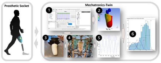
Figure 1.
Overview of the mechatronics-twin framework that allows both virtual and physical replications of prosthetic socket device. The virtual replication is supported by two services: ➊ Biomechanical modeling and simulation; and ➋ FEA. The physical replication is supported by three services: ➌ Prototyping with 3D printing and integrating; ➍ dynamic testing by Stewart platform; and ➎ sensor data acquisition and collection. The analysis is supported by the service ➏ operation condition analysis and anomaly detection.
For the overall methodology, the support can be either generic or specific. The generic cases are related to the simulation and testing of some predefined stumps and sockets, in combination with some well-defined in-socket pads for overall state space exploration and design guide. The specific cases are related to individual configurations and analysis together with more specific operational scenarios. It is useful for covering critical situations not solved by the generic cases. As a fundamental step, the specific configuration of a stump needs to be reconstructed by combining and processing images from several noninvasive measurement methods, including 3D scanning for geometry, Computerized Tomography (CT) scanning for the bony structures, and Magnetic Resonance Imaging (MRI) scanning for the stump soft tissue. To determine material properties of a specific amputee residual limb, a modern SWE (Shear Wave Elastography) method [6] is preferrable. The replication by the test stump is then based on a mixture of hyper-elastic silicone for a reasonable conformance with the material properties [7]. Moreover, the Stewart platform is a robotic manipulator where the motion and force profiles can be programmed. This means that certain peculiarities of the gaiting of individuals (e.g., gait period, ground reaction forces, etc.) can then be reproduced.
For the analysis of intra-socket conditions, we assume the operational conditions of concern follow the semantics of stochastic finite-state automaton [8]. In particular, we also consider the socket operation within gait cycles as a Markovian Process [9]. During physical testing, specific sensors are used for measuring the actual the intra-socket pressure conditions. More formally, we assume the sensor reading at time t is based on a discrete state of socket operation at the same time instance. Due to measurement uncertainty, the sensor function is described with the following probabilistic expression:
Given the condition of state , the current state of socket operation is independent of all the states prior to . The state transition representing a specific socket operation in gait cycles as a Markovian Process, which is given by the following probabilistic expression:
These probabilistic models can be defined in many different ways, such as by a mixtures of Gaussian distributions, a Bayesian network, or a neural network. Together, they constitute the quintessential mechanism for the perception and analysis of socket operational conditions.
3. Related Work
Transfemoral (above knee) amputation is a surgical procedure performed to remove the lower limb above the knee joint when that limb has been severely damaged via trauma, disease, or congenital defect. Essentially, the usage of the prosthetic device aims to restore the ambulation and self-esteem of the amputee as much as possible. The major components of a transfemoral prosthesis include socket, suspension, knee joint, pylon, and feet [10]. Among these prosthetic components, the socket serves as the interface between the residual limb and the prosthesis. It must protect the residual limb and appropriately transmit the forces associated with standing and ambulation. The most frequently reported critical pressure load range measured in the ischial containment socket during gait is between 60–69 kPa [11,12,13,14]. Any pressure load value outside this range could imply poor load distribution and reduced comfort level [15]. In operation, some typical socket-related issues include low bio-mechanical fitness, hampered dynamic control, unnecessary pain, and medical complications (e.g., skin lesions). One reason for this is that the intra-socket operational conditions are inherently individual, resulting from very specific volume fluctuations, tissue evolvements, body dynamics, etc.
To support the socket design, a computer-aided socket design approach has been proposed [16]. The key features consist of digital socket sculpting and patching, together with the graphical modeling procedure however, the tool does not offer any decision support or use any measured operation data. More recent work by [17] present a virtual tool for allowing the emulation of various actual socket operations. The aforementioned work was fostered with shape optimization techniques to automate the search for a socket design solution [18]. In [19], a modeling–simulation analysis workflow has been developed to provide insights about the stump–socket interaction using patient specific configuration data. However, the usability and effectiveness of these methods are hampered as no information about the actual socket operation were involved in the analysis. Without knowing the pressure distribution over the stump, it is very difficult to associate socket fitness and comfort with the socket shape and therefore it is very difficult to propose rectification actions that will improve socket design. Reconstructing the pressure distribution over the stump requires the use of pressure sensors embedded in or attached on the socket. In addition, it requires models, which based on the point-measurement generated by the pressure sensors can provide an estimation for the pressure distribution.
For the design of a prosthetic socket, a perception of the intra-socket dynamic load conditions would constitute an important basis that helps the prosthetists to optimize the configuration for improved operational fitness and comfort. One recent approach to development of embedded sensors through fully personalized liners is presented in [20]. The feasibility of this approach was demonstrated through experiments with a transtibial amputee. Another sensor design and development approach is found in [21], addressing especially some key performance issues, including accuracy, repeatability, and hysteresis. Meanwhile, several other studies show that FEA is also a useful method for estimating the intra-socket pressure distribution given the dynamic loads of a gait cycle. For example, the study by [22] suggested FEM can be classified as an alternative method to evaluate the pre-fabrication prosthetic device. In [23], an investigation of FEA for estimating the dynamic interactions between limb and socket was also introduced. The socket and femur were defined as elastic materials, while the bulk soft tissues were defined as a hyperelastic material. Results for fast dynamic modeling of a stump-socket interaction are presented in [24], including a support for real-time soft-tissue deformation in high conformance with corresponding FEA results. Yet, recent research demonstrates there is still a lack of complete frameworks that include embedded operation sensing, biomechanical analysis, socket optimization design, and experimental validation.
As one approach to modern limb prosthesis, our work is searching for an integration of technologies to support novel sensory and data analytic capabilities. The overall concept of our mechatronics-twin framework is similar to the notion of digital-twin in regard to the replication of a physical target system on the basis of measurements [25]. By the notion of mechatronics, we refer in particular to the effort of developing the framework with a synergetic integration of mechanical, electronic, and electrical solutions, with the key features ranging from biomechanical modeling and simulation, to physical emulation by a Stewart manipulator, and to operation sensing with printed sensors and advanced analysis functions. The framework differs from a digital-twin by also enabling a combination of virtual replication (by digital means) and physical replication (by the robotic manipulator). The approach addresses especially the challenge of complex biomechanical dynamics of prosthesis operation as well as the need of physical replica for data generation and sensor calibration. Clearly, any approaches that rely only on the amputees will not be preferable. This would, in the worst case, cause further trauma to the amputees.
For the physical dynamic testing, our approach adopts the printed wearable soft sensor Quantum Technology Super Sensor (QTSS™) [26] as the base technology for the intra-socket dynamic pressure measurement. Such a choice is motivated by the facts that such sensors could be more robust against environmental disturbances (e.g., vibration, acceleration, or temperature fluctuation) and more transparent for the intra-socket deployment, compared to other pressure sensor technologies, such as resistive transducer, piezoelectric transducer, optical pressure transducer, and capacitive transducer [27]. As a kind of Force Sensing Resistor (FSR), the sensel of the QTSS™ sensor strip consists of material with quantum conduction that exhibits a change of resistance according to the pressure applied on its surface. Meanwhile, as for many other applications of print wearable electronics, some fundamental performance concerns need to be carefully managed, such as regarding the drift (i.e., the change of measurement over time with the same load), hysteresis (i.e., the divergence of measurement in loading and unloading), and lack of repeatability (i.e., the ability of repeating a measurement with the same load) [28,29,30,31]. For successful usage of wearable sensors for intra-socket condition measurement, sensor calibration becomes therefore important.
For the calibration of wearable resistive sensors, it is necessary to take the actual operational conditions into consideration. One reason for this is that the curvature and surface hardness of prosthetic socket could affect sensor accuracy [32]. Moreover, different bio-mechanical configurations and gait behaviors also lead to different dynamic load conditions that in turn may interfere with the sensor drift and hysteresis, as well as other frequency response characteristics negatively. To cope with such a fundamental issue, we adopt neural networks as a special type of probabilistic model for being able to learn the sensor functions directly based on in-socket test data and to use the same data-driven strategy to facilitate sensor re-calibration. In concept, our approach is similar to the usage of probabilistic models for the treatment of uncertainties in robot perception [33,34,35,36,37]. We use in particular Autoencoder (AE), which is a specific variant of deep learning neural networks typically used for signal denoising and data compression [38,39,40] to support an unsupervised learning-based synthesis of sensor models. The advantage of using an AE over using other neural networks such as Multilayer Perceptron (MLP) [41] is that the sensor’s uncertainty due to process or measurement errors can be fine-tuned.
Qualified simulation and dynamic testing constitute the basis for characterizing the operation conditions. Such measurement data are fundamentally time series data, i.e., sequential data over time (e.g., the daily values of a currency exchange rate). There are specific classification algorithms for solving the corresponding classification problem, such as AutoRegression Moving-Average (ARMA) [42]. The performance of such classical time series analysis methods depends however often on the availability of a big amount of data with strong seasonality. The deep learning approaches, such as RNN [43], LSTM [44], and GRU [45], may have a good performance in predicting the data, while working only as black boxes. The state-based methods [46], such as Hidden Markov Model (HMM), and Dynamic Bayesian Network (DBN), allow the incorporation of some existing domain-knowledge about system observability, dynamics, and causality, and thereby could be better optimized for situations with delimited data as well as uncertain measurements. In other words, these methods could have better resilience against the sparsity of data, compared to neural networks with the performance depending on the amount of data available for training. For the design of our perception system, we consider therefore HMMs as a core method for coping with the targeted dynamic process, which is inherently stochastic and only partially observable. Similar work can be found in the area of robotics with promising results [47,48]. As a special type of Bayesian Inference (BI) [46,49], HMM is widely used in speech recognition [50,51], natural language modeling [52], on-line handwriting recognition [53], and for the analysis of biological sequences such as proteins and DNA [54,55]. Anomaly detection refers to the identification and classification of system conditions that differ from some preferred conditions. It could be supported directly by a reasoning of patterns in data, such as with SVM and K-NN [52,56,57,58]. The classification could also be supported with probabilistic classification [59]. On the basis of HMM, probabilistic classification allows a quantification of the discrepancies through statistical inference.
4. Modeling and Simulation of Overall Operational Conditions
The first two services of the mechatronics-twin framework (i.e., the service ➊ and ➋ shown in Figure 1) provide the support for virtual replication of socket operation. The goal is to elicit the most fundamental operational characteristics of a prosthetic device as an integral part of an amputee. In particular, it gives an estimation of the piston-forces and moments within the amputee stump-socket assembly during walking. Knowledge of such physical interactions is essential for a more detailed analysis of stump and prosthesis dynamics. The work is based on OpenSim [60], which is an open source tool for the modeling, simulating, and analyzing of neuromusculoskeletal systems, and ANSYS Workbench [61], which is a commercial software tool for advanced FEA of intra-socket load distribution.
The work starts with a quantification of amputee body geometries, sizes of the pelvis-femur structure, and prosthetic socket based on a combination of measurement and estimation. As described previously, stump measurement by scanning constitutes the basis for identifying the properties of the femur. These geometry data are not only essential for visual representation of the bodies, but also important in the estimation of piston-forces with inverse dynamics when combined with a configuration of associated body masses. To achieve good scaling in biomechanical models, proper measurements of the limbs are required to determine the joints connecting the various bodies. The masses of the residual limb are initially approximated by equating the volumetric density of the default healthy limb to the residual limb. The Static Optimisation Tool of OpenSim is then used for a further adjustment of these masses regarding the kinematics and ground reaction forces of the test subject. In [62], a similar approach is used to develop a transfemoral biomechanical model in OpenSim to estimate joint torques.
A biomechanical model for identifying the piston-forces of transfemoral or transtibial prosthesis within dynamic gait cycles is then constructed with OpenSim as shown in Figure 2. In particular, an amputee leg model, shown in Figure 3, is developed to stipulate the related multi-body parameters of particular concern. These include: (1) Interface_r, representing the imaginary rigid joint between the femur and the socket located at the COM (Center of Mass) of the stump and (2) Interface_SP, representing the joint between the socket (S) and femur pylon (P). During a gait cycle, the piston-forces and moments are related to the contact forces between stump and socket as shown in Figure 3. The conjunction of all force vectors over the discrete regions of stump surface t at each specific gait phase is equivalent to the piston force and moments of the same stump. The contact force at each region is a composition of normal force experienced from the pressure and shear force of the same region.
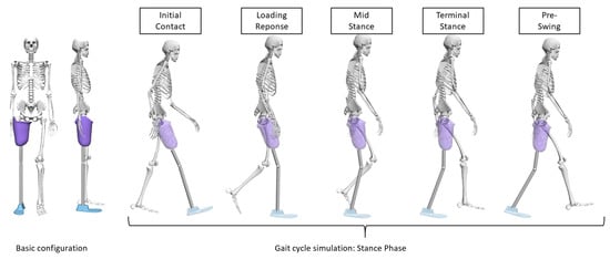
Figure 2.
A snapshot of biomechanical model and related gait phases.
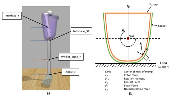
Figure 3.
Basic force tensors determining the intra-socket loads condition. (a) Basic configuration of an amputee leg model integrating transfemoral socket and stump (Right Leg). (b) Basic force tensors determining the intra-socket loads condition.
Given such force and moment data, the piston-forces and moments are calculated according to the simulated ground reaction forces during gait cycles and the corresponding multi-body transformation through the Inverse Dynamics Tool of OpenSim. In Figure 4, one example of the piston forces and moments over 7 gait cycles is shown. They are represented in terms of percentage of gait cycle. The sampling frequency for the simulation is 100 Hz. These internal joint reaction data are then exported for the analysis of socket-stump interface conditions by FEA (i.e., the service ➋), to provide an effective characterization of possible intra-socket load conditions of concern before any further physical tests.
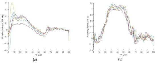
Figure 4.
One example of piston forces and moments over seven consecutive gait cycles, shown by seven trajectories: (a) Rotation moment around X-axis (lateral-medial axis) and (b) piston force along X–axis (lateral-medial axis).
Within the mechatronics-twin framework, the FEA by ANSYS Workbench provides the support for establishing the virtual behaviors relating to the contact forces on stump surface, based on the internal joint reaction data from the biomechanical modeling and simulation. In addition, the analysis also provides insights about contact forces and displacement on the interface of stump and socket. The work begins with a setup of the FEA model by importing the geometries of the stump, socket, and femur to the DesignModeler of ANSYS Workbench. The simulation setup also includes defining the material properties of the bodies in terms of density, Young’s modulus, and Poisson’s ratio, or in the case of hyperelastic composition in terms of the Mooney–Rivlin parameters. Due to the complex interplay of surface conditions, modeling with conventional software such as MATLAB Simscape Multibody would be a less preferred option. Currently, our framework supports a basic homogeneous linearly elastic material model, in correspondence to the physical stump replicas to be produced with silicone mixtures as described in Section 5 below. The calculated internal joint reaction data by OpenSim are thereafter used as the inputs to the FEA software. See Figure 5 for one example of the derived pressure load conditions by FEA.
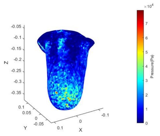
Figure 5.
One example of average pressure load of seven consecutive gait cycles (medial-posterior).
5. Physical Prototyping and Dynamic Testing by Stewart Platform
The services of physical prototyping and dynamic testing (i.e., the service ➌ and ➍ shown in Figure 1) are responsible for producing the physical replica of femur-stump assemblies and prosthetic sockets, according to a measurement of related conditions of femurs, stump assemblies, and sockets. For the prototyping, 3D printing is used mainly due to its efficient lead times as well as its support for a geographical distribution of activities (e.g., having the patient measurement in one region of the world and the testing in another region). The stump replicas are produced by a shell mold casting process using silicone mixtures in correspondence to the simulation support mentioned previously, for which the shell is first created based on the geometry of the stump. The hyperelastic material properties of the silicone can be either estimated according to the respective product specification or precisely determined using the rolling indentation probe method introduced in [7]. Similarly, a femur prototype is also generated by printing and integrated with the stumps. The related design tasks are supported by Meshmixer [63], which is a composition tool for arbitrary surface meshes, see Figure 6a.
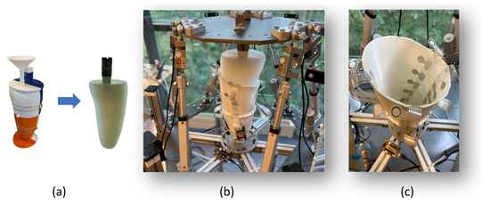
Figure 6.
The physical prototyping and dynamic testing: (a) The shell mold casting process of silicone stump. (b) The physical test-rig with the femur-stump assembly and prosthetic socket mounted on the Stewart manipulator. (c) The sensors deployed inside the socket for measurement of dynamic pressure load conditions.
Within the mechatronics-twin framework, physical testing is supported by a Stewart manipulator. The goal is also to refine, verify, and validate the corresponding virtual behaviors using the physical prototypes of femur-stump assembly and prosthetic socket, see Figure 6b. Each leg of the Stewart manipulator is mounted with a load cell and a linear actuator for the motion control. The tests are carried out based on specific force references derived from biomechanical modeling and simulation. As one key step in the process of motion control, the kinematics and dynamics of dynamic testing are defined based on a lumped-parameter model approximation of the socket-stump-femur assembly. In particular, each leg of the Stewart manipulator, representing one Degree of Freedom (DoF) of the platform, is modeled by a specific parameterized spring-mass-damper model. The complex operational behaviors of prosthetic devices are generated by a composition of these models together. Currently, our framework supports the estimation of lumped parameters for each DoF including the polar coordinates based on a pattern search algorithm similar to [64]. For the motion control of testing, the current framework adopts a cascaded force-position control approach, where the kinematics of the Stewart platform is estimated using the actuator positions and forward kinematics through a Newton–Raphson approximation [65]. The load conditions are measured by the printed wearable soft sensor QTSS™ (Quantum Technology Super Sensor), shown in Figure 6c.
6. Sensor Data Acquisition and Collection
6.1. Sensor Data Acquisition by AE
One part of the service ➎ (shown in Figure 1) is the support for sensor data acquisition, relating to the identification of a sensor function for each individual QTSS solution as defined in Equation (1). The design goal is to effectively manage and treat the measurement uncertainty caused by the inherent variations in sensel design, printed electronics, and intra-socket interactions. Due to the operational complexity, we opt for a data-centric approach to this task. In particular, a specific variant of deep learning neural networks, referred to as Autoencoder (AE), is used to capture the functional relation between the sensor signal data (i.e., voltage) and the possible source dynamic load conditions (i.e., measured pressure). Such a data-driven approach to sensor calibration, as mentioned before, is motivated by the unique variation of specific contact surfaces among measurement points (e.g., varying curvatures of the intra-socket regions), as well as the inherent performance uncertainty of specific printed electronics (e.g., exhibiting drift, hysteresis, and repeatability). To this end, all deep-learning neural network-based methods could in fact be useful by providing support for encoding the expected nonlinear transformations, while filtering the undesired operational disturbances or uncertainties. The main reason for choosing AE over other deep-learning neural network-based methods is due to its transparency in terms of its support for an explicit intermediate latent space representation. Such an intermediate representation is useful not only for justifying the robustness of a calibrated sensor function regarding its dynamic operational ranges, but also for compressing raw sensor data for effective storage and transmission.
AE has a feed-forward structure with two neural networks. The design is characterized by the following parameters:
where refers to the input data and refers to the output data; is the encoder function, ; H represents the latent variables in the AE; and is the decoder function, . Autoencoders are trained to minimize reconstruction errors: . The training and usage AE as a sensor function is given in Algorithm 1. In our case, the training data for AE are generated by deploying the sensors within socket and then subjecting it to some well-defined reference cyclic pressure loads (i.e., the ground truth data). Since the AE design is trained with reference cyclic pressure loads, the outputs recover such load conditions, while removing all measurement uncertainties during the same intra-socket operational conditions. During the training phase, it is also possible to compare directly the outputs with the reference inputs in the manner of supervised learning. Gaussian noises can also be added to the inputs during training or calibration for improving the robustness of sensing.
| Algorithm 1: Training and using AE for sensor data treatment. |
Result: Input: Train signals (voltage) , test data , Ground truth for trainset . AE Training Mode for Sensor Calibration: AE Operation Mode: |
6.2. Sensor Data Collection by HMM
Another part of the service ➎ (shown in Figure 1) is the support for sensor data collection, responsible for the encoding of measured socket operational conditions. Since the physical intra-socket dynamic conditions can only be estimated by the outputs of sensors, we use HMM [66] to build a Bayesian network that integrates the probabilistic models of Equations (1) and (2) for the inference of likely intra-socket dynamic conditions. The inference is conducted as a well-structured form of BI, where possible pressure load conditions are inferred based on the probabilistic characteristics of pressure observation and process dynamics. The outcome typically includes the estimations of likely states and state paths, which constitute the basis for further operational condition analysis, such as classification or prediction.
Essentially, a HMM model defines a discrete-time stochastic dynamic process with a sequence of finite operational states with associated probabilistic observations by sensing. The model is usually displayed as a directed graph of Bayesian network as shown in Figure 7, defined by the following 5-tuple of parameters:
where, Z is a sequence of hidden or latent states of random variables due to the state transition in the dynamic process of socket operation. For a time interval with T discrete instances, it is given as () for the latent states at the discrete time instances t. X is a sequence of T observations of the latent states by sensor in the form of () for the observations at the time instances of t during T. Each latent state has its condition defined by some random variables, which correspond to the intra-socket pressure load. We discretize the pressure load into a set of N discrete hidden states S = {} and let the condition of be given according to the state variable S. Similarly, we consider there are M possible values of the obviation with {}. denotes the initial probability distribution of () regarding the N latent states. The progress of dynamic process (i.e., the edges in Figure 7) is captured by A and B. A defines the probabilities of state transition (Equation (2)), given as a stochastic matrix for the state transition model with elements {}. From every latent state i, each represents the probability of reaching another state j, with . B defines probabilities of state observation (Equation (1)), given as a stochastic matrix with elements {}. From every latent state i, each represents the probability of reaching an observation m, with .
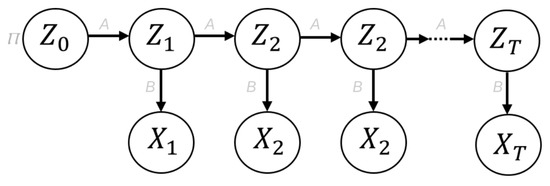
Figure 7.
A graph representation of Hidden Markov Model (HMM), where the node corresponds to the states and sensor observations (i.e., and ), and the transition and observation probabilities are denoted by the edges.
HMM has its parameters trained with data. In particular, the states are defined by a discretization of the physical properties of concern. For example, the intra-socket pressure load 0–100 kPa can be divided evenly into N discrete states with S = {}. We refer the measurement data as , given as the observation sequence for re-scaled logic time intervals T. For probabilistic execution progress description, we denote one probabilistic path of execution progress through T with and the most likely path of execution progress with . The most likely states at each time instance t in T in such paths are denoted with and . For example, a could have one valid path given by () with (i.e., state at the time instant 2 is ) and (i.e., state at the time instant 4 is ), while the most likely path is given by () with (i.e., state at the time instant 2 is ) and (i.e., state at the time instant 4 is ). As a result, a trained HMM model characterizes some with its parameters . The training itself follows the concept of MLE (Maximum Likelihood Estimation) through a fitting of the parameters with the data set that has M samples and N Latent states:
here, the training with essentially identifies the parameters of the model that maximize the conjunctive probability of all related samples . The computation is normally supported through dynamic programming approaches such as with the Baum–Welch algorithm [46], which is a special case of the Expectation Maximization (EM) algorithm for fitting the parameters of HMM (i.e., the state transition model, the emission model, and the initial state distribution) according to the observed data. The model training procedure is shown with Algorithm 2.
| Algorithm 2: Training HMM-based cluster model for the description of reference operation. |
Result: Input: , K fordo end Note: N refers to the number of discretized states for the load conditions; k is one of the K number of temporal clusters; is the data set from comfortable socket usage; refers to the that is labeled as Comfort. It is derived from the HMM model trained with for the same data set ; refers to the for a . |
Within the mechatronics-twin framework, the trained HMM models constitute the basis for inferring different operational scenarios. That is, when fed with a specific new observation data set , labeled as Obs, the trained HMM model defines the most likely path of execution progress :
As preparation for comparing different operational scenarios, the time series data of inferred operational paths are further grouped according to the phases of gait progress. This means that the of time interval T is segmented into K number of time-based soft clusters, referred to as temporal clusters. Such a clustering enables the alignment of similar operational phases in different gait cycles despite the actual lengths of their T. Moreover, each temporal cluster is assigned a unique Gaussian Kernel, shaped by the corresponding execution progress data of that are mapped to the model. Each cluster k has the following parameters:
where represent the Gaussian mean and variance of execution progress data , which are the data of mapped to the cluster ; and K is the total number of such clusters for the time interval T. For the mapping of execution progress data series to the K clusters, a temporal cohesion criterion is used and given by RBF (Radial Basis Function) [67] defined as follows:
where refers to M logic time instances associated to the inferred execution progress data in the time interval of length T; is a reference time point for each K-th cluster of the total K classification clusters for the same time interval of length T; is a scaling constant. In effect, with this RBF-based criterion, each progress data will be weighted differently in different classification clusters.
For establishing a reference trajectory for operation classification and anomaly detection, the training of HMM models is preferred to be based on the data that represent comfortable socket usage. Such a data set, denoted with , could be collected from test cases that may have delimited gait dynamics (e.g., with slower paces), or specific socket configurations (e.g., with specific liner choices), yet are perceived to be comfortable by the user.
7. Operation Condition Analysis and Anomaly Detection
This service of operation condition analysis and anomaly detection (i.e., the service ➏ shown in Figure 1) is responsible for quantifying similarity or discrepancy of measured operational conditions. The design is focused on the classification of collected dynamic operational conditions with the procedure shown with Algorithm 3. For each set of newly-collected operation data , we use the pre-trained HMM model based on comfort data for inferring its most likely path of execution progress (see Equation (6)) as follows:
where and are the parameters in the model of that characterizes the k-th temporal clusters of the reference execution path ; is a term for the sensitivity of k regarding the likelihood. As a notation, refers to the sequence of all over the time interval T. For each execution progress , we detect thereafter the anomalous condition with the following dynamic threshold criteria , given as a function of the likelihood of one or multiple observations:
| Algorithm 3: Detecting anomalous operational conditions using HMM-based cluster model. |
 |
8. Case Study and Results
For the evaluation of our approach, we used OpenSim [60] models for the simulation of biomechanical behaviors and ANSYS [61] models for the identification of reference intra-socket pressure distribution. The physical stump replica is produced through a shell mold casting process using a silicone mixture with Shore Hardness A26. This hardness rating corresponds to a homogeneous linearly elastic material model with a Young’s modulus (E) of MPa and Poisson’s ratio () of , which is subsequently used in defining the material model in FEA [68]. The physical tests are supported with a printed wearable QTSS™ sensor strip inside the socket. The results of dynamic testing by the Stewart platform show that the proposed control strategy is capable of achieving the required magnitude and wave form of the dynamic load cycle. However, a phase shift of the measured data can also be observed, mainly due to the computation delay. This restricts the current dynamic testing to relatively slow gait cycles. The implementation of data analysis functions is done with the hmmlearn [69] and scikit-learn [70] package in Python.
The identification and calibration of the sensor function have been done by applying some standard periodic load cycles with known pressure conditions, recording the measurement outputs of such experiments, and thereby training an AE (Autoencoder) as the sensor function for the nonlinear transformations, see Figure 8. Within the AE, both the encoder and decoder have three layers respectively. The topological structures of these two parts are also made mirror-symmetrical with 50–150–200 neurons in size. During the training process, we also added some white noise in order to improve the robustness of this sensor function. To get a smooth regression curve of sensor modeling, we use Leaky ReLu (Leaky Rectified Linear Unit) as activation functions for the encoder and decoder. We used the MSE (Mean-Square Error) as the loss function.

Figure 8.
Results of the sensor function () trained with AE (Autoencoder) and MLP (Multilayer Perceptron). For the sensor function trained with AE, the MSE (Mean-Square Error) figures of pressure decreasing and increasing phase are around 0.024 and 0.017, respectively. These could be compared with the MSE figures of the sensor function trained with MLP for the same data, which are 0.035 and 0.021 respectively. While the overall performances of these two methods are quite similar to each other, the results of AE are smoother, such as readings between 4 and 9 KPa of the pressure increasing phase. (a) Pressure decreasing phase. (b) Pressure increasing phase.
The training of HMM for Bayesian Inference of intra-socket load conditions in different operational scenarios is based on specific data sets of measured socket operational data. The training procedure follows the description of Algorithm 2, with the comfort operation data and seven discrete latent states. Figure 9a shows the corresponding operational data, with different color points for highlighting the results from temporal clustering according to the criterion of temporal cluster cohesion defined by Equation (8). Figure 9b shows the inferred Gaussian characteristics of execution progress by comfort data (as defined with Equation (7)) in temporal clusters. Through the variable , it is possible for the confidence interval that constitutes a basis for anomaly detection as defined by Equation (9).
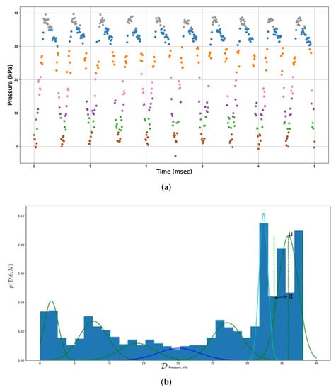
Figure 9.
Characterizing execution progress based on temporal clustering. (a) Temporal clustering for execution progress data of multiple gait cycles. (b) Gaussian characteristics of execution progress data in multiple temporal clusters.
With trained HMM models characterizing socket operations, the anomaly detection aims to reveal the operational anomalies in terms of undesired intra-socket load conditions (e.g., too high pressure level) or operational failures of a sensor itself (e.g., broken electrical wire) according to the probabilistic divergence of operation data. Due to the support of temporal clustering, possible temporal drifts on timeline (e.g., load with the right pressure level but not at the right phase in a gait cycle) can also be detected with the same measure. Such an anomaly detection capability is normally not possible with conventional classification methods such as Support Vector Machine (SVM). Figure 10 shows the results of the HMM-based inference of execution progress. The anomaly detection is based on an estimation of execution progress (according to Equation (9)) and the dynamic threshold (according to Equation (10)), shown with the log-likelihood data in the same figure.
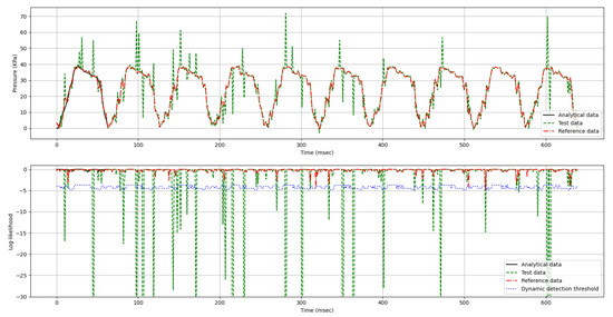
Figure 10.
The execution progress trajectories and the detection of anomalies by dynamic threshold. The analytical data is the round truth data generated by a simulation-based FEA (Finite Element Analysis) of a quadrilateral transfemoral socket with well-defined amputee gait cycles. The reference data represent the load conditions with comfortable socket operation. For the evaluation of algorithmic design, each data set contains around 600 data. The Test data represent the measurement from specific operational scenarios containing anomalies.
For an optimized detection threshold (Equation (9)), we set = 2.6, which gives a confidence interval of around in each Gaussian distribution. Such a dynamic threshold allows us to effectively treat reasonable dynamic pressure fluctuations, such as due to the inherent bio-mechanical effects of socket operation at a specific phase of a gait (e.g., relating to the interplay with soft tissue of amputee stump). For the overall evaluation, we also compare the performances of our dynamic threshold criteria and some other fixed static thresholds. As shown by Table 1, the dynamic approach could in general outperform those static approaches regarding the rates of FP (False Positive) and FN (False Negative). The main reason is that the combination of HMM and a temporal clustering with logic time for the phase alignment in our design together constitutes an effective means for fine-grained detrending of operation data with strong stochasticity.

Table 1.
False Positive, False Negative, and precision with a different threshold.
9. Conclusions
This paper presents a novel mechatronics framework that integrates advanced modeling, simulation, testing, and data analysis for an effective exploration of complex operational behaviors of prosthetic sockets. It serves as the analytical replica of the prosthetic operations with both virtual and physical behaviors for effective data-driven analysis and the avoidance of unnecessary trauma to the amputees. As one fundamental strategy for effective characterization of stochastic dynamic processes, we incorporate trained probabilistic models in terms of neural network and HMM. Such a data-driven approach allows us to effectively cope with the operational complexities of prosthetic sockets and embedded sensors. This also facilitates anomaly detection by probabilistic classification and dynamic threshold. One key research objective of our work is to promote an integration of technologies and scientific methods, as called for by several research communities and engineering domains (e.g., computer science, bioengineering, etc.), as well as application and industrial areas (e.g., prosthetics, printed wearable electronics, etc.). The overall contribution is characterized by a novel combination of emulation, perception solutions, and data analysis methods.
The results by case study show that the proposed solutions can fulfill the expected goals. Meanwhile, the current design of this framework would open up many perspectives for future research. To further address the fundamental challenges in analyzing the dynamic conditions of prosthetic sockets, two venues are of particular interest for future work. One venue is related to the improvement of biomechanical simulation and the FEA-based analysis. In further studies, the modeling support can be enhanced with a mixture of heterogeneous friction coefficients as well as more complex hyperelastic material models for the stump. The simulation and testing cases can also be automated for a different load or gait conditions. As our current work is focused on the identification of possible ways for producing physical replicas, a further elaboration of the design would be of interest, especially regarding the tradeoff among replica fidelity, emulation performance, and production cost. Another venue is related to the inclusion of multi-modality in the measurement and classification of prosthetic socket operation by means of higher-dimension tensor for collecting and analyzing the data from multiple sensors. To this end, we believe that VAE (Variational Autoencoder), another variant of Bayesian Inference, could be useful. For example, it could provide effective treatment of more complex probabilistic models for stochastic dynamic processes. Algorithms based on LSTM/RNN can also be integrated with an Autoencoder for sensor data treatment.
Author Contributions
Overall conceptualization and methodology by D.C. Biomechanical modeling and simulation by S.O., in collaboration with D.C., P.V. and M.K.; FEA, physical prototyping with 3-D printing and integrating by S.O. Dynamic testing with Stewart platform by S.O. and K.N.T. The sensor deployment for dynamic testing by P.V. and M.K. The design of algorithms for sensor data acquisition and collection, operation condition analysis, and anomaly detection by D.C. and P.S. All related software programs implemented by P.S. The case study was done by all authors. D.C. was responsible for the research supervision. All authors contributed to writing, reviewing, and editing. All authors have read and agreed to the published version of the manuscript.
Funding
This work was supported by the research project SocketSense, funded by the European Union’s Horizon 2020 research and innovation programme under grant agreement no. 825429 (https://www.socketsense.eu/) (accessed on 23 November 2021).
Acknowledgments
The test-subject data such as residual limb geometry, weight, height, and age were provided by Ossur (https://www.ossur.com) (accessed on 23 November 2021) based on a pilot study.
Conflicts of Interest
The authors declare no conflict of interest.
References
- The O&P EDGE and the Amputee Coalition. Amputee Patient Comfort and Compliance. inMotion 2021, 21, 5. [Google Scholar]
- Mijailovic, N.; Gavrilovic, M.; Rafajlovic, S.; Ðuric-Jovicic, M.; Popovic, D. Gait phases recognition from accelerations and ground reaction forces: Application of neural networks. Telfor J. 2009, 1, 34–36. [Google Scholar]
- Paternò, L.; Ibrahimi, M.; Gruppioni, E.; Menciassi, A.; Ricotti, L. Sockets for limb prostheses: A review of existing technologies and open challenges. IEEE Trans. Biomed. Eng. 2018, 65, 1996–2010. [Google Scholar] [CrossRef]
- Engsberg, J.; Springer, J.; Harder, J. Quantifying interface pressures in below-knee-amputee sockets. J. Assoc. Child. Prosthet.-Orthotic Clin. 1992, 27, 81–88. [Google Scholar]
- Silver-Thorn, B.; Steege, J.W.; Childress, D.S. A review of prosthetic interface stress investigations. J. Rehabil. Res. Dev. 1996, 33, 253–266. [Google Scholar]
- Eby, S.F.; Song, P.; Chen, S.; Chen, Q.; Greenleaf, J.F.; An, K.N. Validation of shear wave elastography in skeletal muscle. J. Biomech. 2013, 46, 2381–2387. [Google Scholar] [CrossRef]
- Liu, H.; Sangpradit, K.; Li, M.; Dasgupta, P.; Althoefer, K.; Seneviratne, L.D. Inverse finite-element modeling for tissue parameter identification using a rolling indentation probe. Med. Biol. Eng. Comput. 2014, 52, 17–28. [Google Scholar] [CrossRef] [PubMed]
- Hopcroft, J.E.; Motwani, R.; Ullman, J.D. Introduction to automata theory, languages, and computation. ACM Sigact News 2001, 32, 60–65. [Google Scholar] [CrossRef]
- Gagniuc, P.A. Markov Chains: From Theory to Implementation and Experimentation; John Wiley & Sons: Hoboken, NJ, USA, 2017. [Google Scholar]
- Geng, Y.; Yang, P.; Xu, X.; Chen, L. Design and simulation of active transfemoral prosthesis. In Proceedings of the 24th Chinese Control and Decision Conference (CCDC), Taiyuan, China, 23–25 May 2012; IEEE: Piscataway, NJ, USA, 2012; pp. 3724–3728. [Google Scholar]
- Lee, V.; Solomonidis, S.; Spence, W. Stump-socket interface pressure as an aid to socket design in prostheses for trans-femoral amputees—A preliminary study. Proc. Inst. Mech. Eng. Part H J. Eng. Med. 1997, 211, 167–180. [Google Scholar] [CrossRef] [PubMed]
- Neumann, E.S.; Wong, J.S.; Drollinger, R.L. Concepts of pressure in an ischial containment socket: Measurement. J. Prosthet. Orthot. 2005, 17, 2–11. [Google Scholar] [CrossRef]
- Kahle, J.T.; Highsmith, M.J. Transfemoral interfaces with vacuum assisted suspension comparison of gait, balance, and subjective analysis: Ischial containment versus brimless. Gait Posture 2014, 40, 315–320. [Google Scholar] [CrossRef]
- Laszczak, P.; Mcgrath, M.; Tang, J.; Gao, J.; Jiang, L.; Bader, D.; Moser, D.; Zahedi, S. A pressure and shear sensor system for stress measurement at lower limb residuum/socket interface. Med. Eng. Phys. 2016, 38, 695–700. [Google Scholar] [CrossRef]
- Mak, A.F.; Zhang, M.; Boone, D.A. State-of-the-art research in lower-limb prosthetic biomechanics. J. Rehabil. Res. Dev. 2001, 38, 161–174. [Google Scholar]
- Travis, R.; Dewar, M. Computer-aided socket design for trans-femoral amputees. Prosthet. Orthot. Int. 1993, 17, 172–179. [Google Scholar] [CrossRef][Green Version]
- Colombo, G.; Facoetti, G.; Rizzi, C. A digital patient for computer-aided prosthesis design. Interface Focus 2013, 3, 20120082. [Google Scholar] [CrossRef]
- Frillici, F.S.; Rotini, F. Prosthesis socket design through shape optimization. Comput.-Aided Des. Appl. 2013, 10, 863–876. [Google Scholar] [CrossRef]
- Ramasamy, E.; Avci, O.; Dorow, B.; Chong, S.Y.; Gizzi, L.; Steidle, G.; Schick, F.; Röhrle, O. An efficient modelling-simulation-analysis workflow to investigate stump-socket interaction using patient-specific, three-dimensional, continuum-mechanical, finite element residual limb models. Front. Bioeng. Biotechnol. 2018, 6, 126. [Google Scholar] [CrossRef]
- Paternò, L.; Dhokia, V.; Menciassi, A.; Bilzon, J.; Seminati, E. A personalised prosthetic liner with embedded sensor technology: A case study. Biomed. Eng. Online 2020, 19, 1–20. [Google Scholar] [CrossRef] [PubMed]
- Hopkins, M.; Vaidyanathan, R.; Mcgregor, A.H. Examination of the performance characteristics of velostat as an in-socket pressure sensor. IEEE Sens. J. 2020, 20, 6992–7000. [Google Scholar] [CrossRef]
- Jamaludin, M.S. Dynamic Analysis of Transfemoral Prosthesis Function Using Finite Element Method. 2020. Available online: https://www.shibaura-it.ac.jp/albums/abm.php?d=1415&f=abm00010339.pdf&n=9.Thesis_Abstract_Syahmi.pdf (accessed on 23 November 2021).
- Henao, S.C.; Orozco, C.; Ramírez, J. Influence of gait cycle loads on stress distribution at the residual limb/socket interface of transfemoral amputees: A finite element analysis. Sci. Rep. 2020, 10, 1–11. [Google Scholar] [CrossRef] [PubMed]
- Ballit, A.; Mougharbel, I.; Ghaziri, H.; Dao, T.T. Fast soft tissue deformation and stump-socket interaction toward a computer-aided design system for lower limb prostheses. Irbm 2020, 41, 276–285. [Google Scholar] [CrossRef]
- Boschert, S.; Rosen, R. Digital twin—The Simulation Aspect. In Mechatronic Futures; Springer: Berlin/Heidelberg, Germany, 2016; pp. 59–74. [Google Scholar]
- Dejke, V.; Eng, M.P.; Brinkfeldt, K.; Charnley, J.; Lussey, D.; Lussey, C. Development of Prototype Low-Cost QTSS™ Wearable Flexible More Enviro-Friendly Pressure, Shear, and Friction Sensors for Dynamic Prosthetic Fit Monitoring. Sensors 2021, 21, 3764. [Google Scholar] [CrossRef]
- Bao, M.H. Micro Mechanical Transducers: Pressure Sensors, Accelerometers and Gyroscopes; Elsevier: Amsterdam, The Netherlands, 2000. [Google Scholar]
- Dabling, J.G.; Filatov, A.; Wheeler, J.W. Static and cyclic performance evaluation of sensors for human interface pressure measurement. In Proceedings of the 2012 Annual International Conference of the IEEE Engineering in Medicine and Biology Society, San Diego, CA, USA, 28 August–1 September 2012; IEEE: Piscataway, NJ, USA, 2012; pp. 162–165. [Google Scholar]
- Hollinger, A.; Wanderley, M.M. Evaluation of commercial force-sensing resistors. In Proceedings of the International Conference on New Interfaces for Musical Expression, Paris, France, 4–8 June 2006; Citeseer: Philadelphia, PA, USA, 2006; pp. 4–8. [Google Scholar]
- Buis, A.; Convery, P. Calibration problems encountered while monitoring stump/socket interface pressures with force sensing resistors: Techniques adopted to minimise inaccuracies. Prosthet. Orthot. Int. 1997, 21, 179–182. [Google Scholar] [CrossRef] [PubMed]
- Polliack, A.; Sieh, R.; Craig, D.; Landsberger, S.; McNeil, D.; Ayyappa, E. Scientific validation of two commercial pressure sensor systems for prosthetic socket fit. Prosthet. Orthot. Int. 2000, 24, 63–73. [Google Scholar] [CrossRef]
- Khodasevych, I.; Parmar, S.; Troynikov, O. Flexible sensors for pressure therapy: Effect of substrate curvature and stiffness on sensor performance. Sensors 2017, 17, 2399. [Google Scholar] [CrossRef]
- Elfes, A. A stochastic spatial representation for Active Robot Perception. In Proceedings of the Sixth Conference on Uncertainty and Al, AAAI, Cambridge, MA, USA, 27–29 July 1990. [Google Scholar]
- Bessiere, P.; Dedieu, E.; Mazer, E. Representing Robot/Environment interactions using probabilities: The “Beam in the Bin” experiment. In Proceedings of the PerAc’94, from Perception to Action, Lausanne, Switzerland, 7–9 September 1994; IEEE: Piscataway, NJ, USA, 1994; pp. 158–169. [Google Scholar]
- Burgard, W.; Fox, D.; Hennig, D.; Schmidt, T. Estimating the absolute position of a mobile robot using position probability grids. In Proceedings of the National Conference on Artificial Intelligence, Portland, OR, USA, 4–8 August 1996; pp. 896–901. [Google Scholar]
- Thrun, S. Learning occupancy grid maps with forward sensor models. Auton. Robot. 2003, 15, 111–127. [Google Scholar] [CrossRef]
- Muller, J.; Rottmann, A.; Reindl, L.M.; Burgard, W. A probabilistic sonar sensor model for robust localization of a small-size blimp in indoor environments using a particle filter. In Proceedings of the 2009 IEEE International Conference on Robotics and Automation, Kobe, Japan, 12–17 May 2009; IEEE: Piscataway, NJ, USA, 2009; pp. 3589–3594. [Google Scholar]
- Vincent, P.; Larochelle, H.; Lajoie, I.; Bengio, Y.; Manzagol, P.A.; Bottou, L. Stacked denoising autoencoders: Learning useful representations in a deep network with a local denoising criterion. J. Mach. Learn. Res. 2010, 11, 3371–3408. [Google Scholar]
- Hinton, G.E.; Krizhevsky, A.; Wang, S.D. Transforming auto-encoders. In Proceedings of the International Conference on Artificial Neural Networks, Bratislava, Slovakia, 14–17 September 2021; Springer: Berlin/Heidelberg, Germany, 2011; pp. 44–51. [Google Scholar]
- Thirukovalluru, R.; Dixit, S.; Sevakula, R.K.; Verma, N.K.; Salour, A. Generating feature sets for fault diagnosis using denoising stacked auto-encoder. In Proceedings of the 2016 IEEE International Conference on Prognostics and Health Management (ICPHM), Ottawa, ON, Canada, 20–22 June 2016; IEEE: Piscataway, NJ, USA, 2016; pp. 1–7. [Google Scholar]
- Franklin, J. The elements of statistical learning: Data mining, inference and prediction. Math. Intell. 2005, 27, 83–85. [Google Scholar] [CrossRef]
- Brockwell, P.J.; Davis, R.A. Time Series: Theory and Methods; Springer Science & Business Media: Berlin/Heidelberg, Germany, 2009. [Google Scholar]
- Rumelhart, D.E.; Hinton, G.E.; Williams, R.J. Learning Internal Representations by Error Propagation; Rumelhart, D.E., McClelland, J.L., PDP Research Group, Eds.; Parallel Distributed Processing: Explorations in the Microstructure of Cognition; MIT Press: Cambridge, MA, USA, 1986; Volume 1, pp. 318–362. [Google Scholar]
- Hochreiter, S.; Schmidhuber, J. Long short-term memory. Neural Comput. 1997, 9, 1735–1780. [Google Scholar] [CrossRef]
- Cho, K.; Van Merriënboer, B.; Gulcehre, C.; Bahdanau, D.; Bougares, F.; Schwenk, H.; Bengio, Y. Learning phrase representations using RNN encoder-decoder for statistical machine translation. arXiv 2014, arXiv:1406.1078. [Google Scholar]
- Anzai, Y. Pattern Recognition and Machine Learning; Elsevier: Amsterdam, The Netherlands, 2012. [Google Scholar]
- Liu, D.X.; Wu, X.; Du, W.; Wang, C.; Xu, T. Gait phase recognition for lower-limb exoskeleton with only joint angular sensors. Sensors 2016, 16, 1579. [Google Scholar] [CrossRef]
- Gu, X.; Guo, Y.; Deligianni, F.; Lo, B.; Yang, G.Z. Cross-subject and cross-modal transfer for generalized abnormal gait pattern recognition. IEEE Trans. Neural Netw. Learn. Syst. 2020, 32, 546–560. [Google Scholar] [CrossRef]
- Huang, Y.; Shao, C.; Wu, B.; Beck, J.L.; Li, H. State-of-the-art review on Bayesian Inference in structural system identification and damage assessment. Adv. Struct. Eng. 2019, 22, 1329–1351. [Google Scholar] [CrossRef]
- Jelinek, F. Statistical Methods for Speech Recognition; MIT Press: Cambridge, MA, USA, 1997. [Google Scholar]
- Juang, B.H.; Rabiner, L.R. Hidden Markov models for speech recognition. Technometrics 1991, 33, 251–272. [Google Scholar] [CrossRef]
- Manning, C.; Schutze, H. Foundations of Statistical Natural Language Processing; MIT Press: Cambridge, MA, USA, 1999. [Google Scholar]
- Nag, R.; Wong, K.; Fallside, F. Script recognition using hidden Markov models. In Proceedings of the IEEE International Conference on Acoustics, Speech, and Signal Processing (ICASSP’86), Tokyo, Japan, 7–11 April 1986; IEEE: Piscataway, NJ, USA, 1986; Volume 11, pp. 2071–2074. [Google Scholar]
- Krogh, A.; Brown, M.; Mian, I.S.; Sjölander, K.; Haussler, D. Hidden Markov models in computational biology: Applications to protein modeling. J. Mol. Biol. 1994, 235, 1501–1531. [Google Scholar] [CrossRef] [PubMed]
- Baldi, P.; Brunak, S.; Bach, F. Bioinformatics: The Machine Learning Approach; MIT Press: Cambridge, MA, USA, 2001. [Google Scholar]
- Rodriguez, A.; Bourne, D.; Mason, M.; Rossano, G.F.; Wang, J. Failure detection in assembly: Force signature analysis. In Proceedings of the 2010 IEEE International Conference on Automation Science and Engineering, Toronto, ON, Canada, 21–24 August 2010; IEEE: Piscataway, NJ, USA, 2010; pp. 210–215. [Google Scholar]
- Hornung, R.; Urbanek, H.; Klodmann, J.; Osendorfer, C.; Van Der Smagt, P. Model-free robot anomaly detection. In Proceedings of the 2014 IEEE/RSJ International Conference on Intelligent Robots and Systems, Chicago, IL, USA, 14–18 September 2014; IEEE: Piscataway, NJ, USA, 2014; pp. 3676–3683. [Google Scholar]
- Salcedo-Sanz, S.; Rojo-Álvarez, J.L.; Martínez-Ramón, M.; Camps-Valls, G. Support vector machines in engineering: An overview. Wiley Interdiscip. Rev. Data Min. Knowl. Discov. 2014, 4, 234–267. [Google Scholar] [CrossRef]
- Statistical Classification. 2020. Available online: https://en.wikipedia.org/wiki/Statistical_classification (accessed on 23 November 2021).
- OpenSim. Available online: https://simtk.org/projects/opensimlatest (accessed on 16 April 2021).
- Ansys. Available online: https://www.ansys.com (accessed on 16 April 2021).
- Mohamed, A. Modeling and Simulation of Transfemoral Amputee Gait. Ph.D. Thesis, University of New Brunswick, Fredericton, NB, Canada, 2018. [Google Scholar]
- Schmidt, R.; Singh, K. Meshmixer: An interface for rapid mesh composition. In ACM SIGGRAPH 2010 Talks; Association for Computing Machinery: New York, NY, USA, 2010; p. 1. [Google Scholar]
- Zanetti, L.R. Lumped Parameter and Modal Models to Simulate Ground Reaction Forces Due to Running. 2021. Available online: https://repositorio.unesp.br/handle/11449/202681 (accessed on 23 November 2021).
- Jakobovic, D.; Jelenkovic, L. The Forward and Inverse Kinematics Problems for Stewart Parallel Mechanisms; University of Zagreb: Zagreb, Croatia, 2002. [Google Scholar]
- Bunke, H.; Caelli, T.M. Hidden Markov Models: Applications in Computer Vision; World Scientific: Singapore, 2001; Volume 45. [Google Scholar]
- Fasshauer, G.E. Meshfree Approximation Methods with MATLAB; World Scientific: Singapore, 2007; Volume 6. [Google Scholar]
- Larson, K. Can You Estimate Modulus from Durometer Hardness for Silicones; Dow Corning Corporation: Midland, MI, USA, 2016; pp. 1–6. [Google Scholar]
- HMM. Available online: https://hmmlearn.readthedocs.io/en/latest (accessed on 16 April 2021).
- Buitinck, L.; Louppe, G.; Blondel, M.; Pedregosa, F.; Mueller, A.; Grisel, O.; Niculae, V.; Prettenhofer, P.; Gramfort, A.; Grobler, J.; et al. API design for machine learning software: Experiences from the scikit-learn project. arXiv 2013, arXiv:1309.0238. [Google Scholar]
Publisher’s Note: MDPI stays neutral with regard to jurisdictional claims in published maps and institutional affiliations. |
© 2022 by the authors. Licensee MDPI, Basel, Switzerland. This article is an open access article distributed under the terms and conditions of the Creative Commons Attribution (CC BY) license (https://creativecommons.org/licenses/by/4.0/).