Abstract
Conventionally, aerial manipulators, when used for inspection, use drone rotors to stabilize the center of gravity (CoG) shifts, which highly affects its performance. This paper discusses the development of a self-balancing lightweight cable aerial manipulator that can be used for construction inspection purposes. The design is based on a 3D-printed, three degrees of freedom (DoF), planar cable manipulator that is mounted on an extended platform below it as a counter-balance mechanism. The actuators control the manipulator links through a cable system, allowing them to be mounted at the system base to reduce the moving mass of the manipulator during operation. The counter-balance mechanism compensates for any shifts in the CoG of the system by actively sliding a counter-balance weight, mainly a battery, which powers the setup. This mechanism can be attached beneath an off-the-shelf quadrotor to solve the problem of CoG shifts. CoG shifts are due to the manipulator operation when a payload or inspection tool is attached to the end effector to perform a given task. For construction integrity inspection, the aerial manipulator must remain stable during the push or slide processes on both flat and curved surfaces while the non-destructive tests are carried out. To validate the effectiveness of the proposed design, an experimental setup was used, and comparisons were made between the compensated and uncompensated tilt angles of the aerial manipulator. Significant tilt angle reductions were observed with an average of 94.69% improvement, undergoing different manipulator motions during different operation scenarios, as a result of an active compensation of the CoG shift and lightweight design of the system, without sacrificing the functionality of the manipulator for the task.
1. Introduction
For structural integrity assessments, especially in construction and oil and gas sectors, frequent non-destructive testing (NDT) must be carried out to monitor and effectively assess the status of various parts of a structure. One of the most common NDT tools used for structure inspection is the ultrasonic depth sensor, a particularly useful tool for when only one surface of the inspected structure is accessible. This testing method is compatible with a wide range of coated and uncoated materials used in construction, such as steel pipelines, storage tanks, plastic piping, rubber linings, epoxies, and ceramics [1]. The main disadvantage of this testing method is the need for a coupling gel. The inspected surface must be prepared by applying a thin layer of coupling gel, which acts as a conductive medium for sound waves generated by the ultrasonic transducer.
Typically, inspections are done manually by a human operator. This method exposes the operator to hazardous work areas, such as high elevations, to reach the inspected surface of the structure. Whilst traditional safety equipment greatly minimize the risk involved in such operations, failing to abide by safety requirements poses potential life-threatening risks. Thus, an interest has risen in automated inspection methods, which eliminate the aforementioned risks while decreasing running costs and conveniently mapping inspection points [2,3].
Unmanned aerial vehicles (UAVs) have been extensively used by both individuals and industries, mostly for recreational and surveillance purposes. However, due to several limitations, there have been few practical implementations of manipulators attached to UAVs. Existing industrial implementations of aerial manipulators include high voltage [4] and surface contact [5] inspections, as well as specific tasks, such as bolt tightening [6] and valve turning [7]. These limitations exist due to aerial manipulators being more susceptible to disturbances since they are not fixed on stationary rigid frames. The two main disturbances that challenge aerial manipulators are the center of gravity (CoG) shifts and the inertial forces caused by the movement of the links [8].
Several attempts have been made to overcome these challenges, each having their own advantages and limitations. Some methods used a slider with a counterweight in addition to propeller thrust to compensate for the CoG shift [9,10]. Others have proposed model-based control schemes that rely on propeller thrust, such as a decoupling transformation [11] and feedback linearization [12]. A solution proposed in [8] utilized a slider that moved the entire manipulator in a direction opposite to the arm motion. This solution, while being lightweight and compact, is not suitable for construction inspection where the manipulator’s end-effector must remain stationary. Another solution was proposed in [13] which showed a counter-balance mechanism that utilized a pantograph-like structure to stabilize the manipulator. However, such a mechanism is mainly used in pick-and-place operations. A suspended aerial manipulator (SAM) was also proposed in [14], which operates by splitting the system into two sections: a main aerial carrier and a winch-suspended manipulator. Thus, the aerial manipulator can easily reach cramped areas, a task which traditional manipulators struggle with due to the large propellers on the attached UAVs [14]. However, this solution requires the development of a separate entity with its own propulsion units which adds to the cost and complexity of the system. Finally, a decentralized approach was proposed in [15] based on the compensation system which involves the utilization of an object slider, similar to the manipulator slider mechanism. However, this system slides only one part of the system, i.e., the battery, to compensate for CoG shifts instead of sliding the entire manipulator.
This paper proposes a lightweight design of a cable aerial manipulator with a CoG shift compensation mechanism that can be used for construction inspection purposes, such as in Figure 1. The purpose of this design is to overcome some of the aforementioned challenges faced by aerial manipulators in construction. The lightweight design and cabling system reduces the CoG shift caused by the manipulator motions compared to other conventional manipulators connected to the UAV and the CoG shift compensation slider mechanism ensures the drone’s stabilization while decreasing the rotor power required for stabilization in conventional methods. The actuators control the manipulator links through a cable system, allowing them to be mounted at the system base to reduce the moving mass of the manipulator during operation. The CoG compensation slider mechanism, with a pulley and belt drive system, actively changes the position of the slider when the system experiences instability based on the control command from the proportional integral derivative (PID) controller. To validate the effectiveness of the proposed method, several experiments were conducted. From the results, it was observed that there was an average of 94.69% improvement in enhancing the stabilization of the aerial manipulator undergoing different manipulator motions during operation.
Figure 1.
The proposed aerial manipulator with UAV.
2. Materials and Methods
The overall design plan, outlining the processes used to build and test the aerial manipulator with a CoG compensation mechanism, is shown in Figure 2. The purpose of the mechanical design is to ensure the structurally stable design of the manipulator and the slider mechanism while minimizing the overall weight and complexity. A motion analysis of the manipulator is then conducted for two reasons: to identify a large enough workspace region in which the slider mechanism can successfully compensate for the CoG shift, and to use the robot kinematics to determine the slider position that will be fed to a motion controller to compensate for motion. Finally, the control system design is to facilitate the motion of the slider.
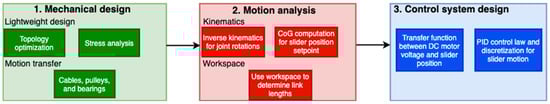
Figure 2.
Design plan for the proposed aerial manipulator with a CoG compensation mechanism.
2.1. Design of the Aerial Manipulator
2.1.1. Design Requirements
There are multiple design criteria that need to be considered while designing the elements of the aerial manipulator system. The system should be light enough to be carried by a 550 size UAV or quadrotor, essentially setting a maximum mass of 1.2 kg for the entire system. It should also have a respectable amount of workspace, allowing the manipulator to reach beyond the area of the UAV, and it must be able to accurately place the end effector at the desired position. Furthermore, the system should be designed in a way which would allow it to handle all the forces applied to it during its use. Additionally, the system must be designed to be fabricated using additive manufacturing methods.
2.1.2. Conceptual Design
The design of the manipulator consists of a 3 DoF open chain serial manipulator mounted under an extended platform below the drone [16]. The platform holds the counterbalance system which compensates for the shift in CoG as the manipulator is operating. This platform allows the workspace of the manipulator to be significantly increased when compared to other configurations. One of the main features of the proposed design is that all the actuators are mounted at the base to prevent the increase in the moving mass of the manipulator when it is in motion. The actuators control the manipulator links through a pulley and cable system, allowing them to be placed away from the links [8,17]. This provides the advantage of having lighter links and a reduced actuator size, as they do not need as much power to operate. The conceptual design in Figure 3 provides a base model to work from to create the detailed model which includes the components necessary to fabricate and assemble the system.
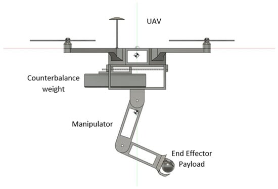
Figure 3.
Conceptual design of the aerial manipulator.
2.1.3. Design of Manipulator Links
The links are designed through a topology optimization method. Topology optimization is a form of structural optimization in which the material distribution and geometry are used to minimize costs, such as its minimal weight, stress, and displacement, as well as to maximize stiffness [18]. It does so while ensuring that the design constraints, in the form of multiple static loads applied to the structure, are met, and the various methods are available and applied commercially [18].
A simple profile of the link is then created, which outlines its length and width. A set of loads is applied to the joints of the link. These loads simulate the forces the links would experience in operation and constitute the design constraints in the optimization problem. The cost function to be minimized is the total weight of the links, subject to the constraints. Topology optimization is conducted using Autodesk Fusion 360 [19] under these conditions to generate the initial profile. This profile indicates the materials needed under the applied loads to perform the same function, while reducing the mass of the component. The optimized profile is then used as a reference to remove material from the original profile.
A stress analysis simulation is then performed to ensure that the component will be able to sustain the applied loads. This is done by computing the internal normal and shear stresses, and ensuring that the von Mises stress does not exceed the material’s allowable maximum stress, [20]. The stress is computed by discretizing the geometry and applying a finite element method on the mesh, which is done here using the commercial software Autodesk Fusion 360 [19]. Figure 4 shows the optimization process, the von Mises stress, and the resulting manipulator assembly.
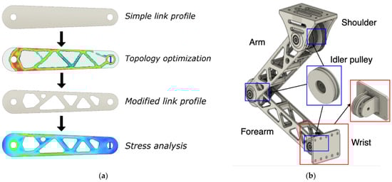
Figure 4.
(a) Link design process; (b) Aerial manipulator assembly.
The cable system consists of cables passing through the hollowed-out links and pulleys at the joint. It facilitates the joint rotations and reduces the motor torque required to rotate the joints. The pulley of the arm operates with a mechanical advantage of 1.5 at a ratio of 3:2, with the actuator rotating 3 times to turn the link 2 times. This limits the motion of the arm to 120 degrees, as the servo motors rotate up to 180 degrees. The pulley of the forearm operates with a ratio of 7:6 with the actuator rotating 7 times to turn the link 6 times, giving a mechanical advantage of 1.16. This limits the motion of the forearm to 154 degrees when the servo motor turns 180 degrees. Idler pulleys are also attached to each joint for a continuous cable connection, as shown in Figure 4.
Once the desired profile is created, all the links are then modelled in 3 dimensions (3D) using the same process with the necessary features, such as pulleys and slots, being added. After all the links are modelled, they are assembled in the following manipulator assembly along with the integrated electronics, as shown in Figure 5.
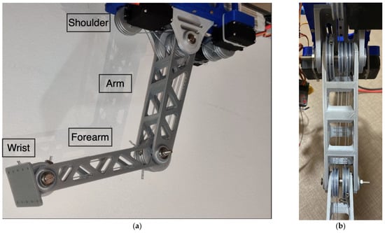
Figure 5.
(a) Integrated cable aerial manipulator; (b) Cable system for one link.
2.1.4. Base Model and Counterbalance System
The base extension platform, to which the manipulator assembly is mounted, is then modelled. The platform is used to house the counterbalance mechanism for CoG compensation and the actuators and electronics necessary for the system to operate. Following the base platform, the counterbalance mechanism is designed. It is an essential part of the system, as it allows for the compensation of the shift in the CoG. A linear guide rail, coupled with a DC motor, is used to drive a slider using a timing belt mechanism. The counterbalance mass, which mainly consists of the battery powering up the system, is attached to the slider compensating for the shift in the CoG. The base platform and counterweight mechanism are shown in Figure 6.
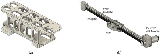
Figure 6.
(a) Base platform; (b) Counterbalance mechanism.
2.1.5. Final Fabrication and Integration
Once all components of the system are modelled, they are assembled into a system. The CoG, interference, and stress analysis are all performed in computer-aided design software to ensure the system operates as desired. Once the design and modelling of the system is finalized, the components are 3D printed using PLA and ABS plastics and are assembled as a mechatronics system. Figure 7 shows the slider-manipulator system.
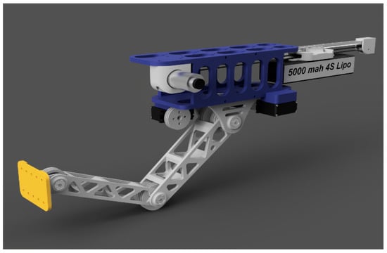
Figure 7.
Final assembly: cable aerial manipulator with a CoG compensation mechanism.
2.2. Modeling and Control
2.2.1. Position Analysis
Our design focuses on minimizing the CoG shift. The low power servo motors, the low operational speeds, and the lightweight design led to the assumption that torques created by actuation and inertial movement are negligible. Furthermore, the system design inherently balances the created torques by moving the counterbalance mechanism in an opposite direction to the manipulator. Thus, the created forces can be taken as disturbances cancelled out by the UAV’s stabilization system. As a result of the physical design, the manipulator undergoes planar motion, with the 3D rotation controlled by the UAV’s movement and rotation. To match the Denavit–Hartenberg (D-H) parameters and the inverse kinematic equations [21], the notations in Figure 8 are introduced.
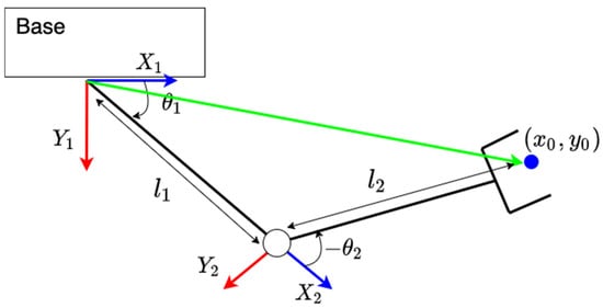
Figure 8.
Kinematic conventions of the manipulator.
To compute the counterbalance weight displacement required to compensate for the CoG shift by the payload, the following equations are derived for the forward kinematics of a 3 DoF 2-link aerial manipulator:
where represent the payload coordinates, the link angles, and the link lengths. Another angle, , was defined to account for the limits of the actuation mechanism. This angle measures the angle of link 2 relative to the drone axis, rather than link 1. It is equivalent to the sum of and .
Similarly, these equations are applied to the links to identify the effect of the link mass and location on the CoG. Once all mass locations are obtained, the following equation is used to obtain the horizontal CoG position:
where, as shown in Figure 9, represents the horizontal position and represents the mass of each component . By setting the CoG displacement to zero and solving Equation (2) for the counterbalance weight (battery) position (),
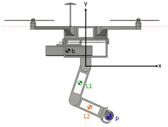
Figure 9.
CoG visual representation.
Here, where the gives the CoG location for each link as a percentage of the link length. The physical parameters describing the kinematics, battery displacement, and densities corresponding to the structural material are given in Table 1.

Table 1.
Physical parameters of the aerial manipulator.
2.2.2. Manipulator Control
The manipulator is developed with two control modes. The first mode is a manual control that allows an operator to directly control the angles of manipulator links using a remote controller. The second mode is inverse kinematic control that allows the operator to input a point in the planar workspace for the manipulator to reach. For the inverse kinematic control mode, the following equations [21] are used to find the final link angles:
where and represent the final link angles, are based on physical design limitations, and represent the desired end effector position, and and represent the respective link lengths.
2.2.3. Manipulator Workspace
The planar workspace is defined as the total 2D area that the manipulator can reach given a set of angle limits. The angle limits of all links are defined by the physical limitations of the design [22]. is limited from −120° to −10° as derived from the physical interference limits of link 1. is limited from 0° to 140° as derived from the physical interference limits of link 2. is limited from −90° to −13° as derived from the physical limits of the servo motor actuating link 2. By adding an additional DoF from the drone rotor rotation, the 3D workspace is also computed. The resulting planar and 3D workspaces of all possible end-effector positions within the workspace limits are shown in Figure 10.
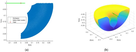
Figure 10.
(a) Aerial manipulator planar workspace; (b) 3D workspace.
The payload position is also limited to the positive x values and the negative y values to simplify the analysis and prevent interference with the drone rotors. Any points with negative x values can be reached by the drone turning 180°. Furthermore, the manipulator is limited to orientations in which the joint connecting links 1 and 2 points downward.
2.2.4. Modeling of the CoG Compensation System
The CoG compensation system consists of a linear guide rail coupled with a DC motor, which is used to drive a slider using a timing belt mechanism. Figure 11 shows a schematic of the CoG compensation system, based on belt-drive models such as in [23].
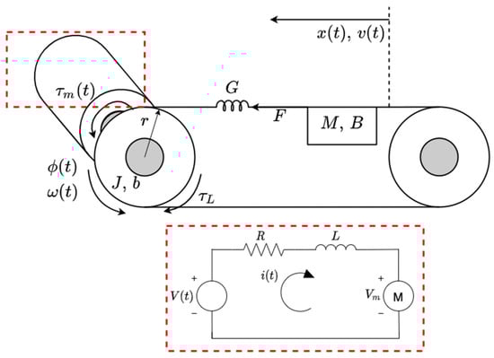
Figure 11.
Schematic representing a model of the CoG compensation system.
Using Newton’s law, the equation representing the counterweight motion is
where and represent the mass, viscous friction damping coefficient, and spring constant representing the belt stiffness, respectively. The timing belt is assumed to be rigid and, as such, we set .
By applying Kirchhoff’s voltage law on the DC motor circuit,
where V is the input voltage, is the current, is the resistance, is the inductance, and is the back emf voltage. Since the electrical time constant is much smaller than the mechanical time constant, the inductance in the motor can be neglected, and Equation (6) can be used to solve for the current.
The equation describing the pulley rotation is
where is the motor torque, is the pulley mass moment of inertia, and is the rotational damping coefficient. is the load torque due to the counterweight, where and are the efficiency and gear ratios of the mechanism. The motor torque and voltage are given by
where and are the torque and electric constants.
To combine the mechanical and electrical systems, we substitute obtained from Equation (6) into from Equations (7) and (8). Noting that , where is the radius of the pulley, we substitute from Equation (5) into , so that Equation (7) can be written as
By taking the Laplace transform of Equation (9), the system transfer function with an input and output is given by
2.2.5. Controller System
The controller system in shown in Figure 12. For this design, the input comes from a handheld remote controller (RC). The RC transmits the signal to the receiver side, which is connected to an onboard Arduino microcontroller. The microcontroller then sends a command signal to the servo motors where the links keep their positions or increase or decrease incrementally, based on the independent joint control approach.
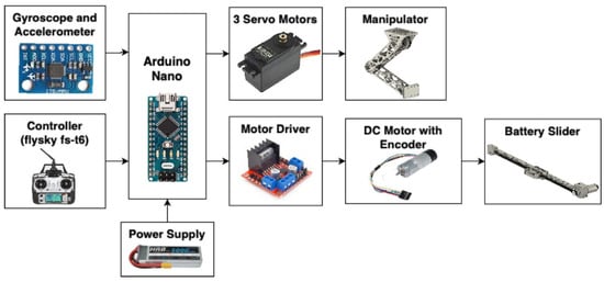
Figure 12.
Mechatronics system for the aerial manipulator.
As a result, the center of mass is shifted. The main objective of the control system is to control the slider position correctly. Our intention is to balance the system to ensure the center of mass of the entire system is preserved. When the manipulator moves, a countering moment is added by moving the battery. The block diagram of the closed loop system is shown in Figure 13.
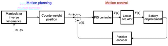
Figure 13.
Control system block diagram.
The desired input position, , of the battery to achieve the balance in the system is calculated based on an equilibrium of moments given in Equation (3). is then fed into the control system, where the linear actuator sends a signal to the counterbalance displacement system (motor driver and DC motor), which provides the required motion for battery displacement. The actual output position of the battery, , is measured using the encoder that is then fed back into the system through the feedback loop. The PID controller adjusts the actuator to accommodate for the difference in the desired output and the actual output. The loop remains active to allow for continuous adjustments to any changes in the input or changes due to the surroundings.
The motion controller used in the battery slider mechanism is a proportional integral derivative (PID) controller. The goal is to achieve a fast response from the PID tuning, while minimizing the transient dynamics as much as possible, ensuring a fast response time, a minimization of overshoot/oscillations, and having a small steady state error.
The PID controller calculates the error, e, as the difference between the actual position of the slider, , and the desired position, . The controller then attempts to minimize this error by sending an adjusted output, u, to the motor that allows the system to approach stability. The control law for the PID controller is
where Kp, Ki, and Kd are the gains of the controllers.
3. Experimental Results
3.1. Experimental Setup
To analyze the effectiveness of the system, the tilt angle evaluation method presented in [13] is analyzed by attaching the manipulator to a single pivot point, as in Figure 14. The tilt angle corresponds to the CoG shift, as the CoG is directly under the apparatus pivot point [13]. During the manipulator’s operation, an MPU-6050 gyro and accelerometer sensor is used to measure the system’s tilt angle [24]. All data is collected directly through the Arduino microcontroller serial port.
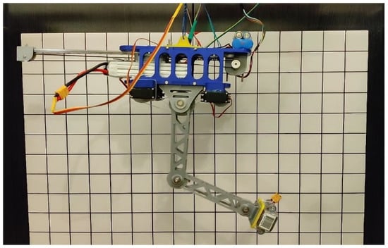
Figure 14.
Experimental setup: cable aerial manipulator with a CoG compensation mechanism.
To validate the effectiveness of the CoG compensation system, the microcontroller is programmed to run through a series of fixed points, utilizing the inverse kinematic control mode. The experiment is repeated twice, once with and once without the battery slider active in the CoG compensation system.
The discrete motion controller with sample time is implemented on the microcontroller. The motor input is the duty cycle, which is discretized for sample by
The controller gains are obtained by manual tuning, with values .
This experimental setup is intended to emulate a hovering scenario with moving arms, in which the UAV position is assumed to be stable.
3.2. Motion Scenarios
The effectiveness of the aerial manipulator CoG compensation mechanism is tested by moving the end-effector to three different locations in the workspace and quantifying the tilt angle reduction by comparing the tilt angle with, and without, the CoG compensation system slider motion. Table 2 shows the motion scenario coordinates and the tilt angle reduction percentage, , where are the average steady-state tilt angle values with and without the CoG compensation mechanism, respectively.
Table 2.
Motion scenario coordinates and tilt angle reductions.
3.2.1. Motion Scenario I
Figure 15 shows the system tilt angle with and without the slider for motion from the initial coordinates (0.153, −0.149) to the final coordinates (0, −0.29) in the planar workspace.
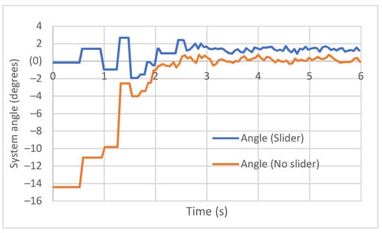
Figure 15.
System tilt angle for a motion from coordinates (0.153, 0.149) to (0, −0.29).
Figure 16 shows the system tilt angle at the coordinates (0, −0.29), with and without the slider.
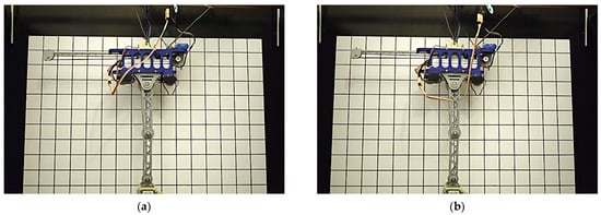
Figure 16.
System tilt angle for (a) compensated, (b) uncompensated systems at coordinates (0, −0.29).
3.2.2. Motion Scenario II
Figure 17 shows the system tilt angle with and without the slider for motion from the initial coordinates (0.14, 0.15) to the final coordinates (0.28, −0.02) in the planar workspace.
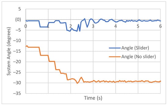
Figure 17.
System tilt angle for a motion from coordinates (0.14, 0.15) to (0.28, −0.02).
Figure 18 shows the system tilt angle at coordinates (0.28, −0.02), with and without the slider.
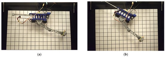
Figure 18.
System tilt angle for (a) compensated, (b) uncompensated systems at coordinates (0.28, −0.02).
3.2.3. Motion Scenario III
Figure 19 shows the system tilt angle with and without the slider for motion from the initial coordinates (0.28, −0.02) to the final coordinates (0.14, 0.15) in the planar workspace.
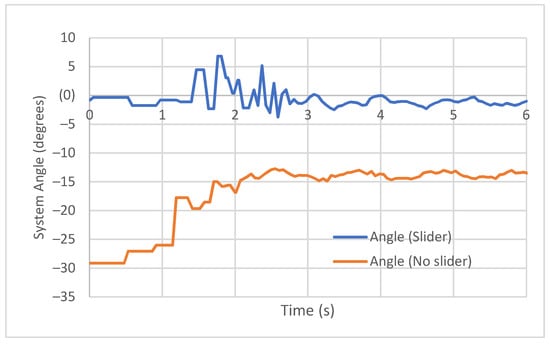
Figure 19.
System tilt angle for motion from coordinates (0.28, −0.02) to (0.14, 0.15).
Figure 20 shows the system tilt angle at coordinates (0.14, 0.15), with and without the slider.
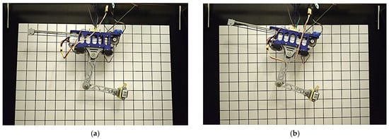
Figure 20.
System tilt angle for (a) compensated, (b) uncompensated systems at coordinates (0.14, 0.15).
4. Discussion
The tilt angle is directly correlated to the shift in the COG of the manipulator. A higher tilt angle equates to a more unstable system when attached to a drone. As seen in the results, as well as Figure 15 and Figure 16, the CoG compensation system greatly reduced the tilt angle from a starting value of −14.4° to an average steady-state value of 1.28° when stabilized. As demonstrated in motion scenario II, the end-effector horizontal position was increased. This sent the tilt angle from −12.5° to −29.4° without compensation but remained close to −0.5° when using the CoG compensation system, which corresponds to a 98.3% improvement based on the tilt angle. The reverse motion of scenario II, which is scenario III, also showed an improvement of 91.08% in the steady-state tilt angle. This validates the effectiveness of the proposed method at enhancing the stabilization of an aerial manipulator undergoing different arm motions during operation with an average of 94.69% improvement, as expected. From the accelerometer data sheet, the sensitivity scale factor tolerance of the sensor is ±3%. Since the sensor is only used to measure and verify the system’s response, a very small error only influences the analysis of collected data. The MG995 TowerPro servo motors used in this system to actuate the manipulator links and the end effector rotate from 0° to 180°. These servos are accurate to 1°. Although this value is small, the error may be influenced by using multiple servos. Two servos are used on the links that affect the position of the manipulator. In turn, the error in the final position value that could be caused by the servos is doubled. The PID controller is used to account for any deviations and errors caused by the DC motor and the encoder. However, there is a small steady state error visible in the results as a result of assuming the belt as being completely rigid in the used setup and the used sensors. Even with the presence of these errors, the main test of stability lies within the tilt angle of the system. The tilt angle is directly correlated to the shift in the CoG; a higher tilt angle equates to a more unstable system when attached to a drone. As seen in the results, the CoG compensation system greatly reduced the tilt angle as expected, effectively stabilizing the manipulator’s CoG.
5. Conclusions
In this work, the design, integration, and testing of a lightweight cable aerial manipulation system for use in structural inspections is proposed, with the purpose of reducing the load on the motors during inspection that results from a shift in the CoG. This is done by developing a CoG compensation mechanism, as well as minimizing the overall weight. The efficacy of the design is experimentally demonstrated by using the compensation mechanism to reduce the tilt angle, yielding a more flexible manipulator workspace.
The system is a lightweight design in three distinct ways: through the utilization of the battery powering the system as an active counter-balance weight in the CoG compensation mechanism, the utilization of lightweight materials and topology optimized designs for the system, and the use of pulley and cable actuation mechanisms for the manipulator links. The last part allows all electrical components and actuators to be mounted on the base of the manipulator; this process reduces their influence on the shifting of the manipulator’s CoG. The weight optimizations of the system results in an increase in the stability, workspace reach, and possible payload mass. Results show a system tilt angle reduction from about 30° without compensation to around 1° on average with compensation. This signifies an effective design capable of providing a stable cable aerial manipulation in a large workspace. After verifying the effectiveness of the CoG compensation mechanism on the static setup, with a flight controller to ensure hovering, the usefulness of the CoG compensation mechanism can be further verified on the drone/quadrotor. Future work will involve testing the mechanism on the quadrotor and quantifying the reduced effort on the rotors’ motors, as well as the transient properties of the end-effector trajectory.
Author Contributions
All authors contributed across the different components of this research. Conceptualization, A.A., I.H.S., M.A. (Muhammad Alvi), M.W.Q., M.A.J. and M.A. (Muhannad Alkaddour); Methodology, A.A., I.H.S., M.A. (Muhammad Alvi), M.W.Q., M.A.J. and M.A. (Muhannad Alkaddour); Supervision, M.A.J.; Validation, A.A., I.H.S., M.A. (Muhammad Alvi), M.W.Q. and M.A.J.; Writing—review & editing, A.A., I.H.S., M.A. (Muhammad Alvi), M.W.Q., M.A.J. and M.A. (Muhannad Alkaddour). All authors have read and agreed to the published version of the manuscript.
Funding
The work in this paper was supported, in part, by the Open Access Program from the American University of Sharjah. This paper represents the opinions of the author(s) and does not mean to represent the position or opinions of the American University of Sharjah.
Conflicts of Interest
The authors declare no conflict of interest.
References
- Fowler, K.; Elfbaum, G.; Nelligan, T. Theory and Application of Precision Ultrasonic Thickness Gaging. Insight 1996, 28, 582–587. [Google Scholar]
- Gasparin, E.; Santi, G.; Nussbaumer, A. Eddy current crack monitoring system for structural health monitoring (SHM) applications. In Proceedings of the 68th International Institute for Welding (IIW) Annual Assembly and International Conference, Helsinki, Finland, 28 June–3 July 2018; pp. 1084–1090. [Google Scholar]
- Tognon, M.; Hermes, A.; Chávez, T.; Gasparin, E.; Sablé, Q.; Bicego, D.; Mallet, A.; Lany, M.; Santi, G.; Revaz, B.; et al. A truly-redundant aerial manipulator system with application to push-and-slide inspection in industrial plants. IEEE Robot. Autom. Lett. 2019, 4, 1846–1851. [Google Scholar] [CrossRef]
- Debenest, P.; Guarnieri, M.; Takita, K.; Fukushima, E.F.; Hirose, S.; Tamura, K.; Kimura, A.; Kubokawa, H.; Iwama, N.; Shiga, F. Sensor-Arm—Robotic manipulator for preventive maintenance and inspection of high-voltage transmission lines. In Proceedings of the 2008 IEEE/RSJ International Conference on Intelligent Robots and Systems, Nice, France, 22–26 September 2008; pp. 1737–1744. [Google Scholar] [CrossRef]
- Ollero, A.; Heredia, G.; Franchi, A.; Antonelli, G.; Kondak, K.; Sanfeliu, A.; Viguria, A.; Martinez-de Dios, J.R.; Pierri, F.; Cortés, J.; et al. The AEROARMS Project: Aerial Robots with Advanced Manipulation Capabilities for Inspection and Maintenance. IEEE Robot. Autom. Mag. 2018, 25, 12–23. [Google Scholar] [CrossRef]
- Car, M.; Ivanovic, A.; Orsag, M.; Bogdan, S. Impedance Based Force Control for Aerial Robot Peg-in-Hole Insertion Tasks. In Proceedings of the 2018 IEEE/RSJ International Conference on Intelligent Robots and Systems (IROS), Madrid, Spain, 1–5 October 2018; pp. 6734–6739. [Google Scholar] [CrossRef]
- Orsag, M.; Korpela, C.; Bogdan, S.; Oh, P. Valve turning using a dual-arm aerial manipulator. In Proceedings of the 2014 International Conference on Unmanned Aircraft Systems (ICUAS), Orlando, FL, USA, 27–30 May 2014; pp. 836–841. [Google Scholar] [CrossRef]
- Ohnishi, Y.; Takaki, T.; Aoyama, T.; Ishii, I. Development of a 4-joint 3-DOF robotic arm with anti-reaction force mechanism for a multicopter. In Proceedings of the 2017 IEEE/RSJ International Conference on Intelligent Robots and Systems (IROS), Vancouver, BC, Canada, 24–28 September 2017; pp. 985–991. [Google Scholar] [CrossRef]
- Baizid, K.; Giglio, G.; Pierri, F.; Trujillo, M.A.; Antonelli, G.; Caccavale, F.; Viguria, A.; Chiaverini, S.; Ollero, A. Behavioral control of unmanned aerial vehicle manipulator systems. Auton. Robot. 2017, 41, 1203–1220. [Google Scholar] [CrossRef]
- Chaisena, K.; Chamniprasart, K.; Tantrairatn, S. An Automatic Stabilizing System for Balancing a Multi-Rotor Subject to Variations in Center of Gravity and Mass. In Proceedings of the 2018 Third International Conference on Engineering Science and Innovative Technology (ESIT), North Bangkok, Thailand, 19–22 April 2018; pp. 1–5. [Google Scholar] [CrossRef]
- Garofalo, G.; Beck, F.; Ott, C. Task-space Tracking Control for Underactuated Aerial Manipulators. In Proceedings of the 2018 European Control Conference (ECC), Limassol, Cyprus, 12–15 June 2018; pp. 628–634. [Google Scholar] [CrossRef]
- Mersha, A.Y.; Stramigioli, S.; Carloni, R. Exploiting the dynamics of a robotic manipulator for control of UAVs. In Proceedings of the 2014 IEEE International Conference on Robotics and Automation (ICRA), Hong Kong, China, 31 May–7 June 2014; pp. 1741–1746. [Google Scholar] [CrossRef]
- Abuzayed, I.; Itani, A.R.; Ahmed, A.; Alkharaz, M.; Jaradat, M.A.; Romdhane, L. Design of Lightweight Aerial Manipulator with a CoG Compensation Mechanism. In Proceedings of the 2020 Advances in Science and Engineering Technology International Conferences (ASET), Dubai, United Arab Emirates, 4 February–9 April 2020; pp. 1–5. [Google Scholar] [CrossRef]
- Sarkisov, Y.S.; Kim, M.J.; Bicego, D.; Tsetserukou, D.; Ott, C.; Franchi, A.; Kondak, K. Development of SAM: Cable-Suspended Aerial Manipulator. In Proceedings of the 2019 International Conference on Robotics and Automation (ICRA), Montreal, QC, Canada, 20–24 May 2019; pp. 5323–5329. [Google Scholar] [CrossRef]
- Ruggiero, F. Decentralized Control of Aerial Manipulators Through a Momentum-Based Estimator. In Aerial Robotic Manipulation; Springer: Cham, Switzerland, 2019; pp. 159–174. [Google Scholar]
- Ruggiero, F. A multilayer control for multirotor UAVs equipped with a servo robot arm. In Proceedings of the 2015 IEEE International Conference on Robotics and Automation (ICRA), Seattle, WA, USA, 26–30 May 2015. [Google Scholar] [CrossRef]
- Aziz, M.A.S.; Yahya, S.; Almurib, H.A.F.; Abakr, Y.A.; Moghavvemi, M.; Madibekov, Z.; Elsayed, A.S.A.; AbdulRazic, M.O.M. Torque Minimized Design of a Light Weight 3 DoF Planar Manipulator. IEEE Trans. Ind. Appl. 2019, 55, 3207–3214. [Google Scholar] [CrossRef]
- Vlah, D.; Žavbi, R.; Vukašinović, N. Evaluation of topology optimization and generative design tools as support for conceptual design. In Proceedings of the Design Society: DESIGN Conference; Cambridge University Press: Cambridge, UK, 2020; pp. 451–460. [Google Scholar]
- Fusion 360; Autodesk: San Rafael, CA, USA, 2020.
- Budynas, R.G.; Nisbett, J.K. Shigley’s Mechanical Engineering Design, 9th ed.; McGraw Hill: New York, NY, USA, 2011. [Google Scholar]
- Lin, S.; Wang, J.; Peng, R.; Yang, W. Development of an Autonomous Unmanned Aerial Manipulator Based on a Real-Time Oriented-Object Detection Method. Sensors 2019, 19, 2396. [Google Scholar] [CrossRef] [PubMed]
- Hafez, O.M.A.; Jaradat, M.A.; Hatamleh, K.S. Stable under-actuated manipulator design for mobile manipulating Unmanned Aerial Vehicle (MM-UAV). In Proceedings of the 2017 7th International Conference on Modeling, Simulation, and Applied Optimization (ICMSAO), Sharjah, United Arab Emirates, 4–6 April 2017; pp. 1–6. [Google Scholar]
- Sollmann, K.; Jouaneh, M. Dynamic modelling of a single-axis belt-drive system. Int. J. Model. 2011, 12, 386–394. [Google Scholar] [CrossRef]
- Huang, J. Design of Angle Detection System Based on MPU6050. In Proceedings of the 7th International Conference on Education, Management, Information and Computer Science (ICEMC 2017), Shenyang, China, 16–18 June 2017. [Google Scholar]
Publisher’s Note: MDPI stays neutral with regard to jurisdictional claims in published maps and institutional affiliations. |
© 2022 by the authors. Licensee MDPI, Basel, Switzerland. This article is an open access article distributed under the terms and conditions of the Creative Commons Attribution (CC BY) license (https://creativecommons.org/licenses/by/4.0/).