1. Introduction
The internal combustion engine (ICE) plays a very important role in transportation, as well as industry and agriculture. Among ICEs, diesel engines are preferred in transportation, specifically in the maritime industry, due to their higher thermal efficiency than gasoline engines [
1,
2,
3,
4]. Diesel engines are being used very commonly in life, so emissions from them are a big problem that needs attention today. In recent years, governments and environmental protection organizations around the world have been paying deep concern about the increasing levels of pollution. This forces them to implement stricter transportation emission regulations [
5]. To meet strict emission regulations, various technologies to improve engine performance while reducing their emission magnitudes are being actively researched. Engine emission reduction technologies are typically divided into three categories: (1) pre-treatment solution; (2) internal treatment solution; and (3) after-treatment solution [
6,
7]. Pre-treatment technologies are related to using alternative or pre-treated fuels with cleaner characteristics instead of conventional fossil fuels. The effectiveness of some types of alternative fuels on engine emission reduction was investigated in our previous works [
8,
9]. Internal treatment technologies are related to improving the fuel combustion quality inside engine cylinders by modifying or/and adjusting one or some of the factors influencing the combustion process. The effectiveness of modifying the fuel injector or changing the fuel injection strategy was reported in our previous studies [
10,
11]. Modifying the engine design is one of the other effective strategies [
3]. The in-cylinder air motion, swirl intensity, charge air temperature and pressure, fuel injector, fuel injection pressure and strategy, and piston bowl geometry shape are key parameters governing the combustion and consequently performance and emission characteristics of ICEs [
3,
12,
13]. Among these factors, piston bowl design plays a crucial role in the mixing quality between the fuel and charge air, which has a direct influence on the engine performance and emission characteristics [
14,
15,
16]. When the piston moves upward in the compression process, the in-cylinder gas is pushed upward, according to the movement of the piston. The piston bowl geometry thus should be optimized to produce better swirling and squish actions that improve the air/fuel mixing quality prior to fuel ignition taking place [
15,
17,
18,
19,
20].
In the past, some researchers had studied the effects of various combustion bowl geometries on the engine performance and emissions of CIEs experimentally. As experimental studies require lots of time, money, and human resource, researchers and scientists turned their strategy toward the theoretical and numerical analyses for the piston bowl optimization techniques [
21,
22]. Raj et al. [
23] researched the air motion inside the cylinder of a 4-stroke diesel engine for four various piston bowl geometries. They found out that piston bowl geometry plays an important role in the fuel/air mixing quality inside the engine cylinder. Specifically, the center bowl on the flat piston was the best from the viewpoint of the tumble ratio, turbulent kinetic energy (TKE), and turbulent intensity with respect to the in-cylinder air motion. Kidoguchi and Yang [
24] mentioned that a piston bowl with a higher squish magnitude and lower throat diameter results in a simultaneous reduction of NOx (oxides of nitrogen) and PM (particulate matter). Li et al. [
25] researched the effects of piston bowl design on a biodiesel-fueled diesel engine with three various piston bowl geometries, namely hemispherical, omega, and shallow depth piston bowls. They reported that the Omega-shaped bowl was more suitable for high-speed engines due to the superior squish flows inside the engine cylinder. Jaichandar and Annamalai [
19] experimentally researched the engine power of a DI diesel engine with toroidal and shallow depth re-entrant piston bowls fueled with biodiesel. The authors reported that the re-entrant piston bowl improved the fuel/air mixing quality, resulting in a performance improvement. Lin et al. [
26] investigated the performance and fuel/air mixing quality for three various piston bowl geometries for a four-stroke diesel engine. Their optimized piston bowl had a positive influence on fluid flow turbulence, fuel/air mixing quality, diffusion combustion phase, fuel oil consumption, smoke, and NOx emissions. Prasad et al. [
27] studied the impact of re-entrant piston bowl geometry on a diesel engine and found out that the higher re-entrant piston bowl produced better TKE and swirl while reducing NOx and soot emissions simultaneously. Venkateswaran and Nagarajan [
28] numerically investigated the effects of piston bowl geometries on a turbocharged diesel engine, and they concluded that enhancement in in-cylinder turbulence has a positive influence on fuel oil consumption, soot, and NOx emissions. Zhu et al. [
29] studied the performance and emissions of a diesel engine with various piston bowl designs. They reported that increasing the toroidal radius led to better combustion efficiency while reducing soot emissions. The re-entrant piston bowl was more suitable for DI diesel engines due to it producing a higher in-cylinder pressure and lower soot formation, which is the same as reported in [
30].
Saito et al. [
30] also studied the effect of piston bowl design on the combustion process of a diesel engine. They concluded that the re-entrant piston bowl was suitable for swirl generation and TKE intensification around the top dead center (TDC). Jaichandra et al. [
17] conducted an experimental analysis on the combined effects of fuel injection timing and piston bowl geometry on the performance of a diesel engine fueled with biodiesel. The research reported that a re-entrant piston bowl could improve engine performance but increase NOx emission. Taghavifar et al. [
31] researched the effects of piston bowl geometry on the in-cylinder flow behavior and performance of the engine and reported that the piston bowl must be fully optimized to achieve the optimum performance.
Khan et al. [
32] numerically investigated the effect of piston bowl geometry on the mixing, combustion, and emissions of a diesel engine and concluded that improving the piston bowl design could form stronger squish flow. This helped to increase air-fuel mixing quality. Xu et al. [
33] studied the effects of piston bowl geometry on in-cylinder combustion and engine performance of a gasoline DI compression ignition engine. The study concluded that, to improve engine efficiency and decrease emissions simultaneously, the piston bowl geometry and injection strategy should be co-optimized. Shojae et al. [
34] investigated the effects of the piston bowl geometry, exhaust gas recirculation (EGR) ratio, and fuel injection timing on the engine performance of a 4-stroke diesel engine in 2022. They concluded that the combination of an optimized piston bowl design, correct fuel injection timing, and appropriate EGR ratio helped to increase engine performance while reducing exhaust gas emissions of the engine. Hao et al. [
35] investigated the combined effects of the injector spray angle and combustion chamber geometry on combustion performance at a full load of a diesel engine using a genetic algorithm. They concluded that the optimization of both the injector spray angle and piston bowl geometry improved the air-fuel mixing quality and thus the combustion process of the engine. This helped to increase engine power while reducing soot unburnt hydrocarbon (HC), and carbon monoxide (CO) emissions. Doppalapudi et al. [
36] performed a survey on the combustion chamber modification to improve engine performance while reducing emissions from diesel engines in 2021. They concluded that the main effect of the combustion chamber modification is an improvement in the air-fuel mixing quality due to greater turbulence inside the engine chamber. This helped to improve the combustion quality and increase the engine performance while reducing most of the emissions, except for NOx emissions.
The literature review concluded that any improvement in fuel/air mixing quality inside the engine cylinder can significantly improve the combustion quality, subsequently improving the performance and reducing the emission formation of the engine. Among many ways to improve in-cylinder flow turbulence for fuel/air mixing improvements in diesel engines, modifying the piston bowl geometry has its own interesting advantages [
37]. However, studies on the influence of piston bowl geometry on heavy-duty engines in the marine sector are very rare in the literature. In addition, although there have been some studies on the effect of piston bowl geometry on internal combustion engines, studies conducted on heavy-duty marine engines are limited. Due to the nature of the marine industry, marine engines will be regularly repaired and maintained throughout their life. During these processes, engine components are very often replaced and/or improved. By assessing the impact of piston bowl geometry on the engine performance and emissions, marine engine repair and operation engineers can select a more suitable piston bowl type for their engine to substitute.
This study aims to specify an effective geometry for the piston bowl of four-stroke DI diesel engines with respect to improving engine power and reducing exhaust gas emissions. The AVL FIRE R2022 code [
38] was used to model the combustion of the fuel and exhaust gas emission formations inside the cylinder of the engine. Three types of piston bowl geometry with various parameters were studied, targeting to improve the performance and emission characteristics of the engine. The study has successfully specified the most effective piston bowl design for a four-stroke heavy-duty diesel marine engine that helps to enhance engine power while reducing emission magnitudes.
2. Numerical Analysis
2.1. Researched Engine Specifications
The research subject of the present work is a 4-stroke DI diesel engine. The influences of piston bowl geometry on the performance, fuel oil consumption, and emission formation of the engine were investigated by modeling the combustion of the fuel and emission formations occurring inside the cylinder of the researched engine. The original piston bowl design of the engine is a U-type shape. This is the baseline for comparison with the other piston bowl shapes. The fuel injector has 10 identical holes with a spray angle of 155° and is mounted in the center of the cylinder head. The main specifications of the researched engine are presented in
Table 1.
2.2. Simulation Cases
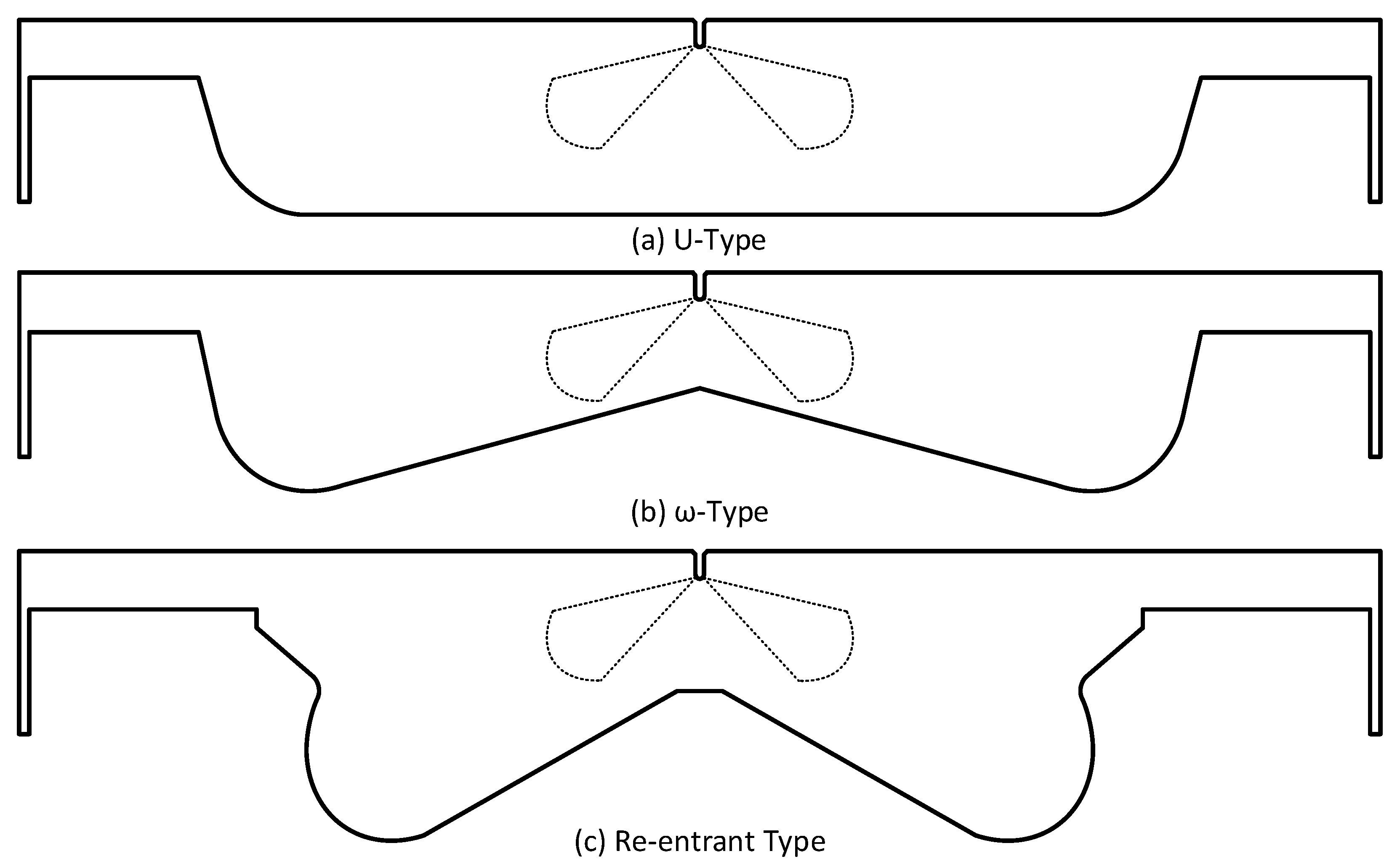
Three different types of piston bowls, namely the U-type, omega (
-type), and re-entrant type, were used to study the influence of the piston bowl design on the combustion process and emission formation characteristics of the engine under the same compression ratio (CR). In all simulation cases, apart from the piston bowl type, all the other factors, including the boundary conditions, initial conditions, and engine working conditions of the engine were kept unchanged.
Figure 1 illustrates the structure of the three various types of piston bowls in this study.
The engine combustion chamber is composed of the cylinder liner, cylinder head, and piston surfaces. In this study, the piston bowl shape of the engine was modified. Therefore, to keep the same CR in all three simulation cases, some main parameters of the piston bowl, such as the bowl diameter, bowl depth, bowl fillet radius, etc., have been adjusted for each type of piston bowl. In addition, to achieve the same calculated CR in all three cases in the CFD analysis as equal to the actual CR of the engine in the experiment, a “compensation volume” was created on the piston top for each case to compensate for the lacking swept volume () of the engine cylinder when building the computational meshes for CFD simulations.
2.3. CFD Models
The commercial simulation software AVL FIRE R2022 (2022 R2, AVL List GmbH, 8020 Graz, Austria) with its advanced computational fluid dynamic (CFD) models had been proved to be well-suited for modeling the combustion of the fuel and emission formations inside the cylinder of IECs with very high accuracy [
38]. In the present study, the ESE (engine simulation environment) diesel platform provide by AVL FIRE R2022 was utilized to simulate the engine working process starting from the IVC (intake valve closing) to the EVO (exhaust valve opening).
The k-ζ-f turbulence model was employed to simulate the fluid flow turbulence inside the engine cylinder. This is a 4-equation model developed from the well-known k-ε 2-equation model. It, therefore, has a higher precision and better simulation stability than the original k–ε 2-equation model [
39]. In the CFD analysis, the mixing process and transport of reactants and products (chemical species) in a combustion problem is modeled by solving conservation equations, such as energy, mass, momentum, species conservations, etc. In this study, the 3-Z (three-zone) extended coherent flame species transport model (ECFM) [
40,
41] was used for the simulation of the combustion of fuel in the engine cylinder. This model is improved from the coherent flame model (CFM), so it contains not only all the features, but also the enhancements of the CFM. It was successfully used in many previous works with very high result accuracy [
8,
9,
42,
43]. Therefore, this study used this model for combustion modeling. This model is detailed and can be referenced in Appendix B of our previous study [
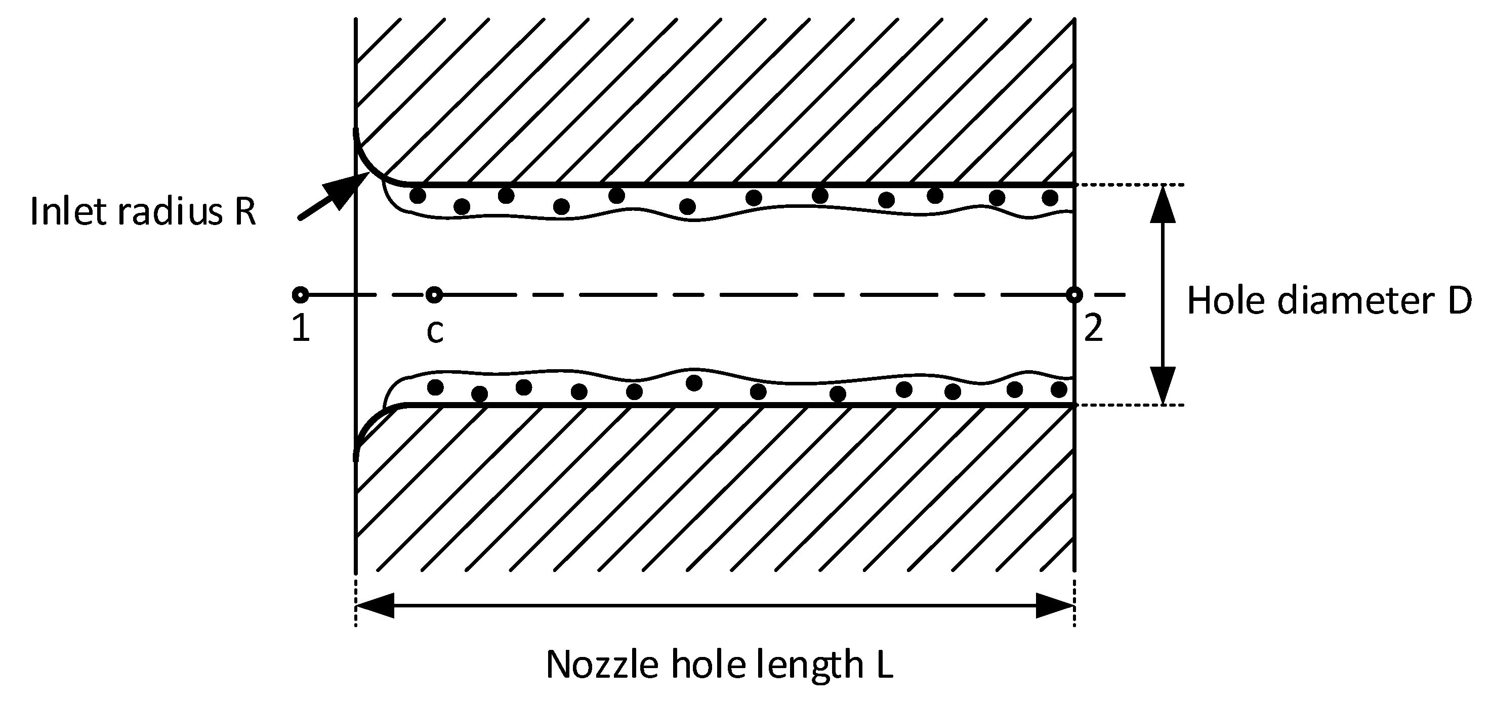
8]. The fuel direct injection process was modeled by the Diesel Nozzle Flow sub-model [
41,
44]. This model offers a simple method for correcting the initial velocities and diameters of the injected droplets owing to cavitation. The model is presented in detail in
Appendix A. The evaporation and breakup processes of injected fuel droplets have been modeled by the Dukowicz and WAVE sub-models [
41,
44], respectively.
The extended Zeldovich mechanism [
41,
45] was employed to model NO formation in the engine cylinder. This mechanism is composed of seven chemical species and three chemical reactions. It had been proved to be able to predict the thermal NO emission formations in ICEs accurately over a wide fuel/air equivalence ratio range in many works [
10,
11,
46,
47,
48,
49,
50]. The formation of soot in the engine cylinder was modeled by the kinetic soot mechanism [
41,
45]. The extended Zeldovich and kinetic soot mechanisms are detailed and can be respectively referenced in Appendix C and D of our previous research [
8]. The droplet-wall interaction between the injected fuel droplets and combustion chamber walls has been modeled by the Walljet1 sub-model [
41,
44]. This model had been developed from the Naber and Reitz spray/wall impingement model [
51]. Other CFD models in this study can be referred to in the references [
41,
44,
45]. The CFD models employed for the simulations in this study are summarized in
Table 2.
2.4. Computational Mesh, Boundary, and Initial Conditions
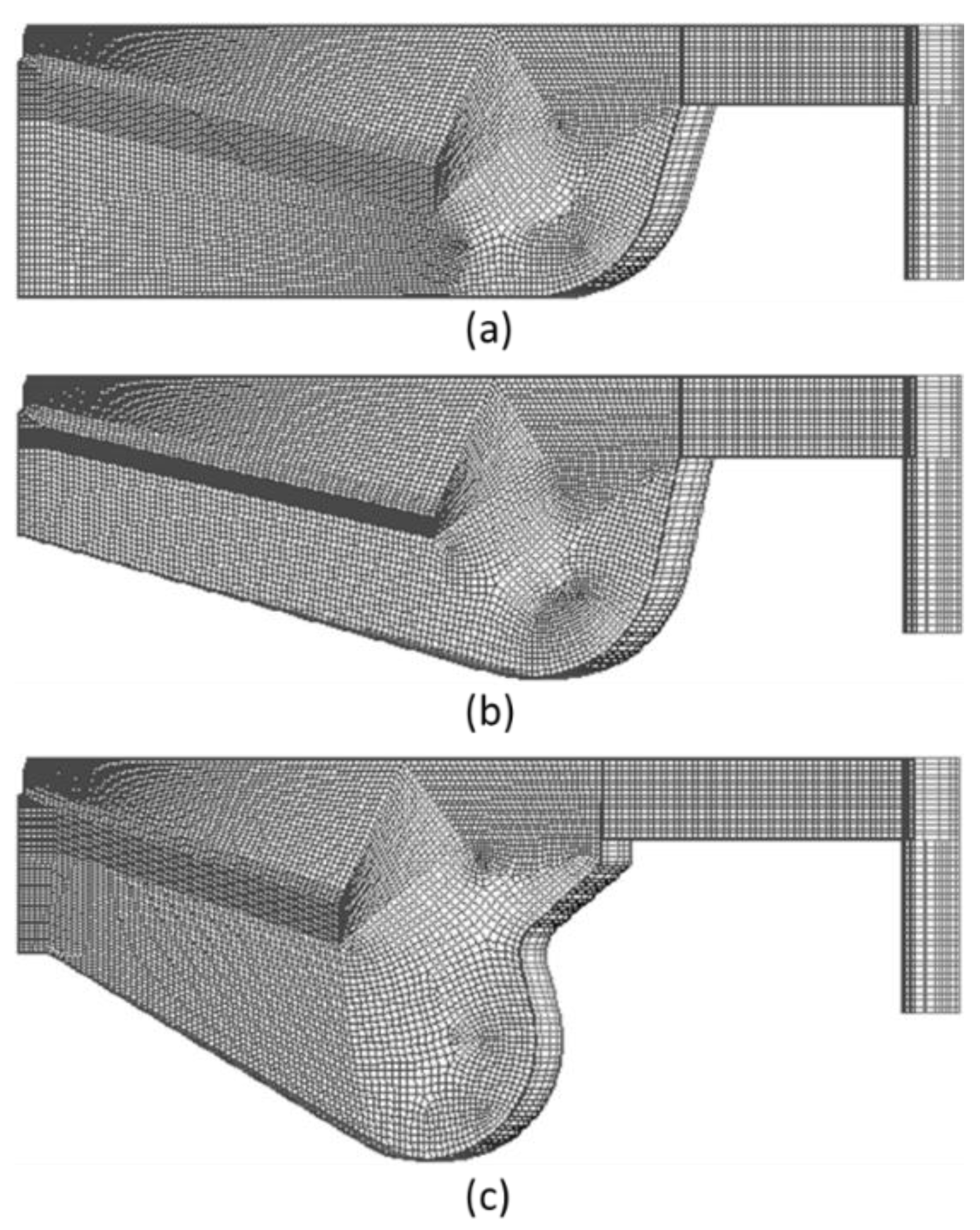
The 3D meshes of the engine combustion chamber for CFD analysis have been created by the ESE-diesel platform. Because of the axial symmetry characteristics of the engine combustion chamber, the injector nozzle has 10 identical holes, and for the computation time saving purpose, only one-tenth of the whole engine combustion chamber has been meshed. The simulation began at the IVC and ended at the EVO of the engine. It was carried out in parallel by a twelve-core AMD Ryzen 7 5800H processor (Advanced Micro Devices, Inc., Santa Clara, California and Austin, Texas, U.S.A.) and took approximately 25 h of CPU time. The computational meshes at the TDC of the three combustion chamber types in this study are presented in
Figure 2.
The surfaces of the piston, cylinder head, and cylinder liner of the engine were defined as impermeable walls. The cylinder liner and cylinder head surfaces were fixed walls, while the piston surface was a movable wall. Due to the axial symmetry characteristics of the cylinder geometry, the two cutting surfaces on the CFD computational domains have been assigned as cyclic boundary conditions (BCs). Diesel oil was injected directly into the engine cylinder at 12 crank angle degrees (CADs) before the top dead center (BTDC) with an injection duration of 32 CADs. During the simulation process, the computational mesh was re-meshed, corresponding to the piston movement by using the dynamic layering re-meshing method. In this method, the boundary layers of the meshes will be collapsed or added depending on the piston movement direction (upward or downward movement). Therefore, the number of layers of the computational dynamic mesh and the number of elements will consequently decrease or increase according to the moving up or down of the piston. In this way, the aspect ratio, skewness, orthogonal qualities, and resolution of the mesh are kept almost constant during the computations. To eliminate the near-wall effect of the cylinder liner and piston surfaces, as well as to accurately capture all the behaviors of the fluid flow near the walls, three inflation layers with a 1.2 mm thickness were applied on these surfaces.
In engine modeling, the time-step size for the simulation is calculated based on the piston speed. In this case, the time-step size was 5.656 × 10⁻⁵ s. However, owing to the complexity of the combustion process, the time-step size of the simulations during the combustion period of fuel (12 CADs BTDC to 20 CADs ATDC) was reduced to 10 times to ensure the convergence of the solution.
In this research, the simulations of the combustion had been performed according to the assumption that the simulated engine was working in a stable thermal situation. The thermal situation on the engine combustion chamber walls was almost stable. With this assumption, the temperature level on the engine cylinder liner surface was set to 197 °C, while the temperature levels on the piston and cylinder head surfaces were set to 297 °C, based on the technical suggestions in the literature [
41]. The temperature of the cylinder liner surface was lower than that of the piston and cylinder head surfaces, owing to the cooling effect of the freshwater cooling system of the engine. The engine was charged with the fresh air by an exhaust gas turbocharger. The temperature and pressure in the engine cylinder at the start of the simulations (i.e., at the IVC) were 37 °C and 2.5 bar, respectively, the same as reported in the engine experiments. Additionally, the properties of the fresh air, such as density, thermal conductivity, viscosity, specific heat capacity, etc. had been set as functions of temperature in order to ensure the right responses of the air to any change in temperature. For the initial conditions of airflow inside the engine cylinder, as has been known, the flow inside the cylinder of a DI diesel engine is characterized by squish, tumble, and swirl intensities. They influence the fuel/air mixing quality between the supplied fuel and charge air. Their turbulent intensities are primarily affected by the inlet valve shape, inlet port design, engine (piston) speed, and inflow velocity of charge air (for DI engines) or fuel-air mixture (for port-injection engines). Because the squish flows inside the cylinders are primarily formed when the piston of the engine reaches the TDC, the characteristics of initial flows inside the engine cylinder are typically characterized solely by tumble and swirl. Based on the engine speed (900 rpm), mean piston speed (9.3 m/s), and charge air pressure (2.5 bar), which causes charge air velocities, and on the guidance suggested in the literature [
41], a level of 2880 (1/min) for tumble and swirl intensities has been set as the in-cylinder flow initial condition for the simulations in this research.
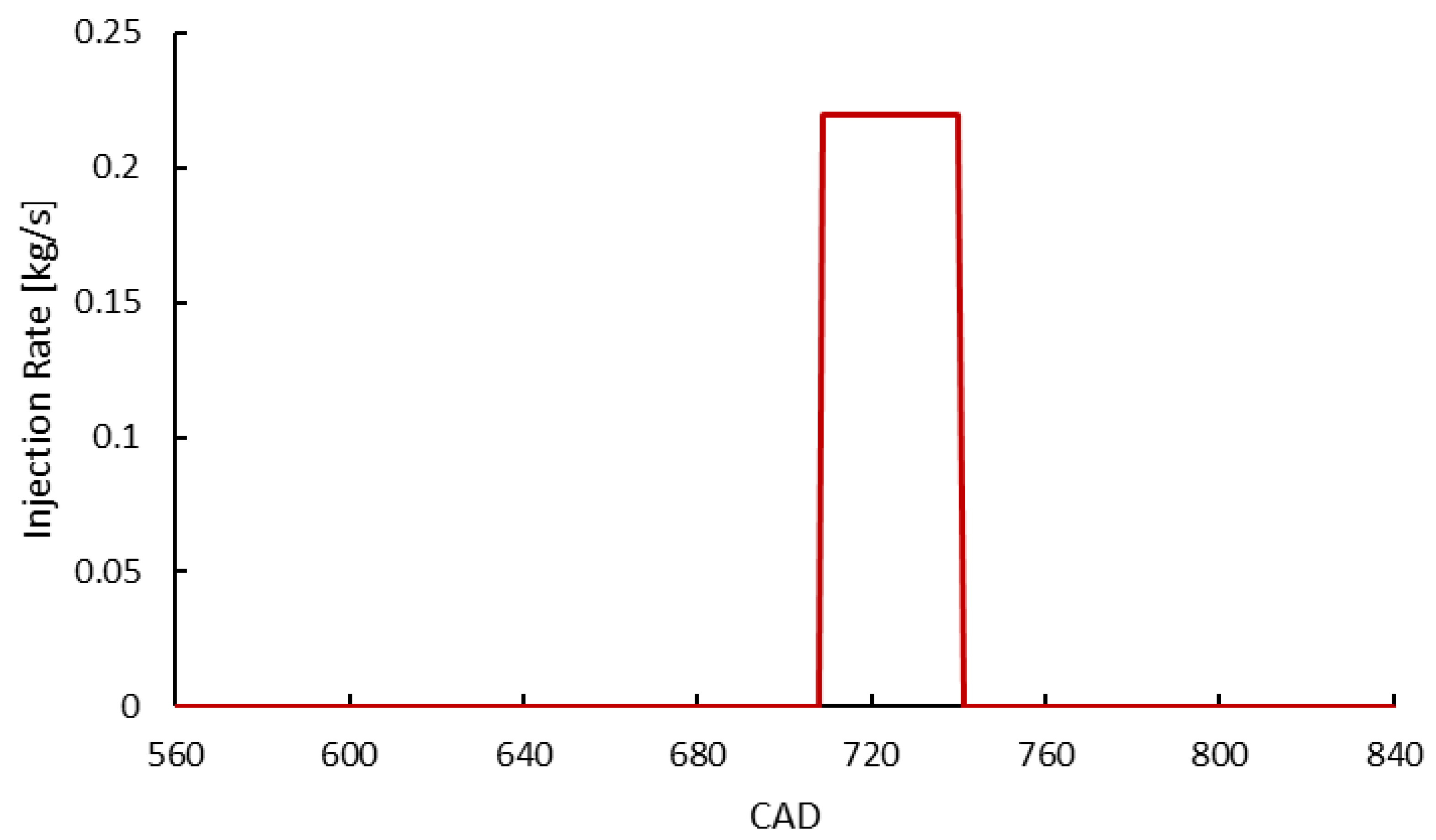
The engine was supplied with a mass flow rate of 70.2 kg diesel oil per hour, corresponding with 0.0195 kg/s. With an engine speed of 900 rpm, the amount of diesel fuel supplied per engine working cycle was 1.3 g. This fuel amount was injected into the engine cylinder in a 32 CADs duration. Therefore, the injection rate of the injector was 0.219375 kg/s. The single injection strategy for fuel injection was applied to this engine. The injection configuration is presented in
Figure 3. This injection configuration was applied to all three piston bowl cases of the engine.
The boundary and initial conditions for simulations were kept the same as in the experiments reported in the technical measurement profile of the researched engine. In the present research, C
13H
23 was employed to represent diesel oil. The main physicochemical properties of diesel oil in the present study had been presented and can be referred to in our previous works [
8,
9,
43], in which all physical properties of diesel oil were set as temperature-dependent to ensure the right response of fuel to any change in temperature.
Table 3 lists the boundary and initial conditions for numerical simulations in this study.
2.5. Analysis of Mesh Independence
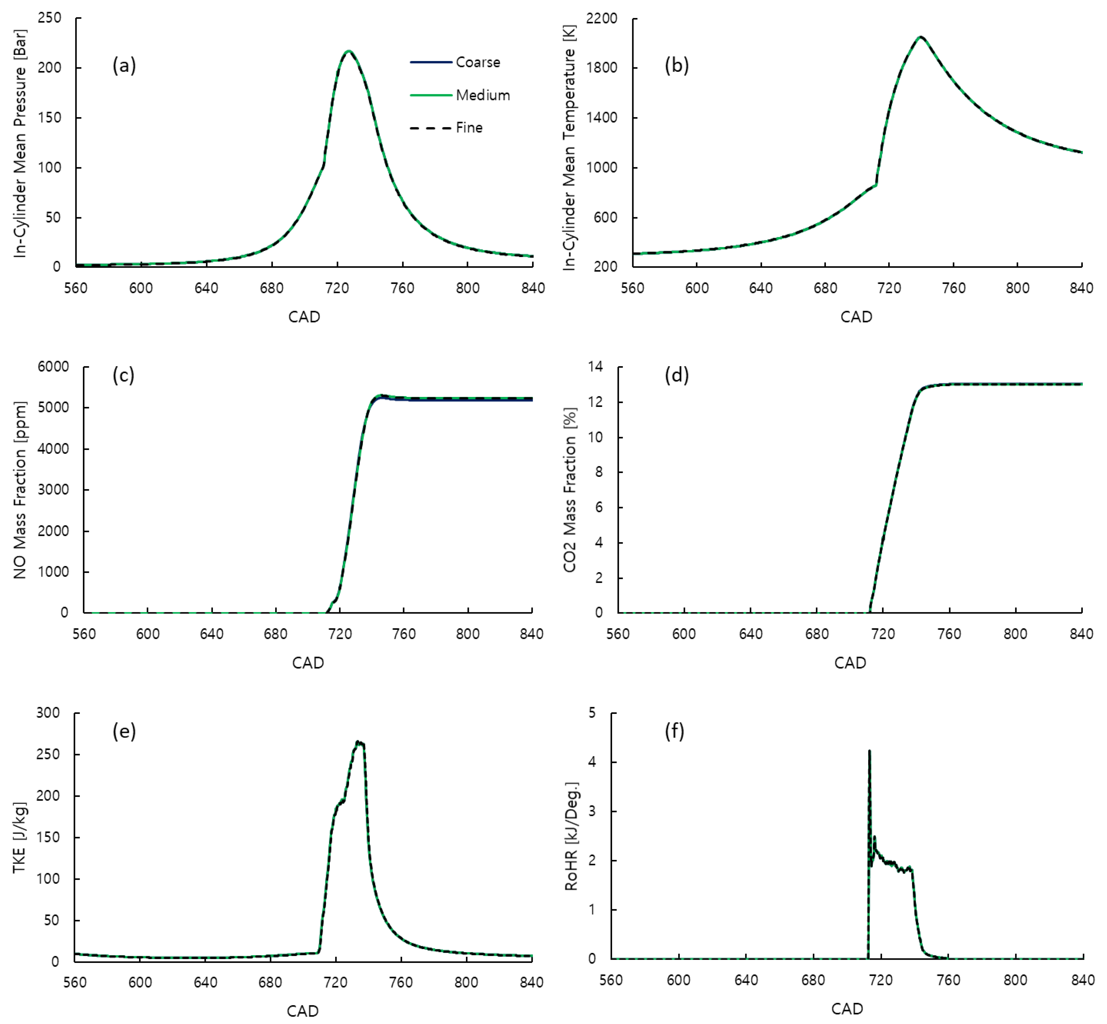
The quality of the computational mesh, or the resolution of the mesh, strongly affects the final CFD result accuracy. On the other hand, mesh resolution also affects computation time. Normally, finer meshes produce better mesh qualities leading to higher accuracies for final CFD results, but prolonging calculation time. As a result, to ensure the final CFD result accuracy and calculation time reasonableness, a mesh independence (sensitive) analysis was carried out. Three different simulations using three various computational meshes, including coarse-, medium-, and fine-resolution meshes, were conducted. A minimum mesh size value of 0.075 mm was set for the fuel injection region of the combustion chamber to ensure that it accurately reflects the fuel injection characteristics of the engine. The final CFD results had then been compared.
Table 4 lists the mesh properties and corresponding calculation times of these three various mesh resolutions.
Figure 4 presents the comparison of the results of the CFD simulations that use those three various mesh resolutions. It is clear that the final CFD results were independent of the computational mesh resolution. Technically, all those three meshes can thus be employed for simulations in this study to achieve not only accurate, but also mesh independent final CFD results. However, the medium-resolution mesh was chosen for the simulations in this study since it took a reasonable calculation time while providing mesh independent final CFD results. It also offers a good resolution for contour analyses.
2.6. CFD Models Validation
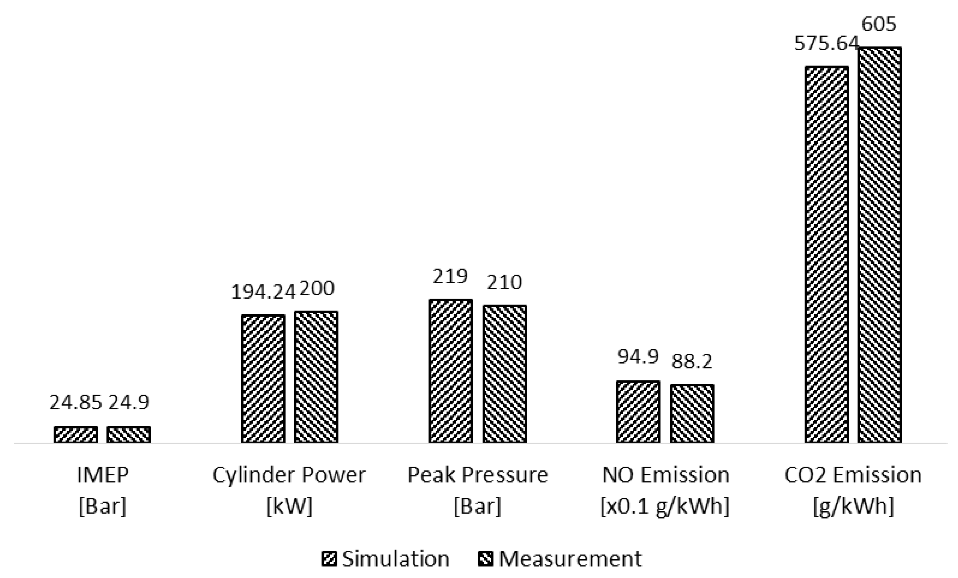
Once the calculation was complete and the convergence was obtained, the energy balance and sum of the mass fractions are examined to confirm that energy and mass had been conserved. The examination pointed out that the energy balances at the end of computations were almost equal to zero, while the sum of mass fractions was equal to 1, confirming the conservations of both energy and mass in the combustion system. The CFD models were then validated by performing a comparison between the simulated and measured results that were reported in the engine technical profile. A comparison between the simulated and measured data is presented in
Figure 5.
Figure 5 really showed a good agreement between the measured and simulated results. Specifically, the deviations between the measured and simulated indicated mean effective pressure (IMEP), cylinder power, and peak pressures were only 0.2%, 2.88%, and 4.286%, respectively. For emissions, the deviations between the measured and simulated specific NO and CO
2 (carbon dioxide) emissions were 7.6% and 4.85%, respectively. After the CFD models had been verified, the verified models were then applied for the simulations in this study.
3. CFD Simulation Results
In order to clearly illustrate the effect of piston bowl geometry on the combustion process and emission formations of the engine, all BCs, initial conditions, and engine operating conditions remained unchanged, except in the modification of piston bowl geometry. The in-cylinder turbulence, temperature, pressure fields, engine performance, fuel oil consumption, and emission formations in all simulations are presented and analyzed in this section.
3.1. In-Cylinder Flow Turbulence
The TKE is typically used to examine the in-cylinder flow turbulence of the ICEs. In fluid dynamics, TKE is the mean kinetic energy calculated for one unit of mass in turbulent flows. Based on the Reynolds and Navier–Stokes equation expressions, TKE can be computed by CFD turbulence models. Physically, TKE is half of the sum of component variances of turbulent velocities, as presented in Formula (1) [
52].
In Formula (1), , , , and , respectively, are the TKE and the velocity components, according to the horizontal directions (x- and y-axis) and vertical direction (z-axis) of turbulent flows. As can be seen, TKE is proportional to the velocity components squared. In another word, it indicates the turbulence level of the in-cylinder flow of the engine. Higher TKEs imply higher fluid flow turbulence levels and vice versa.
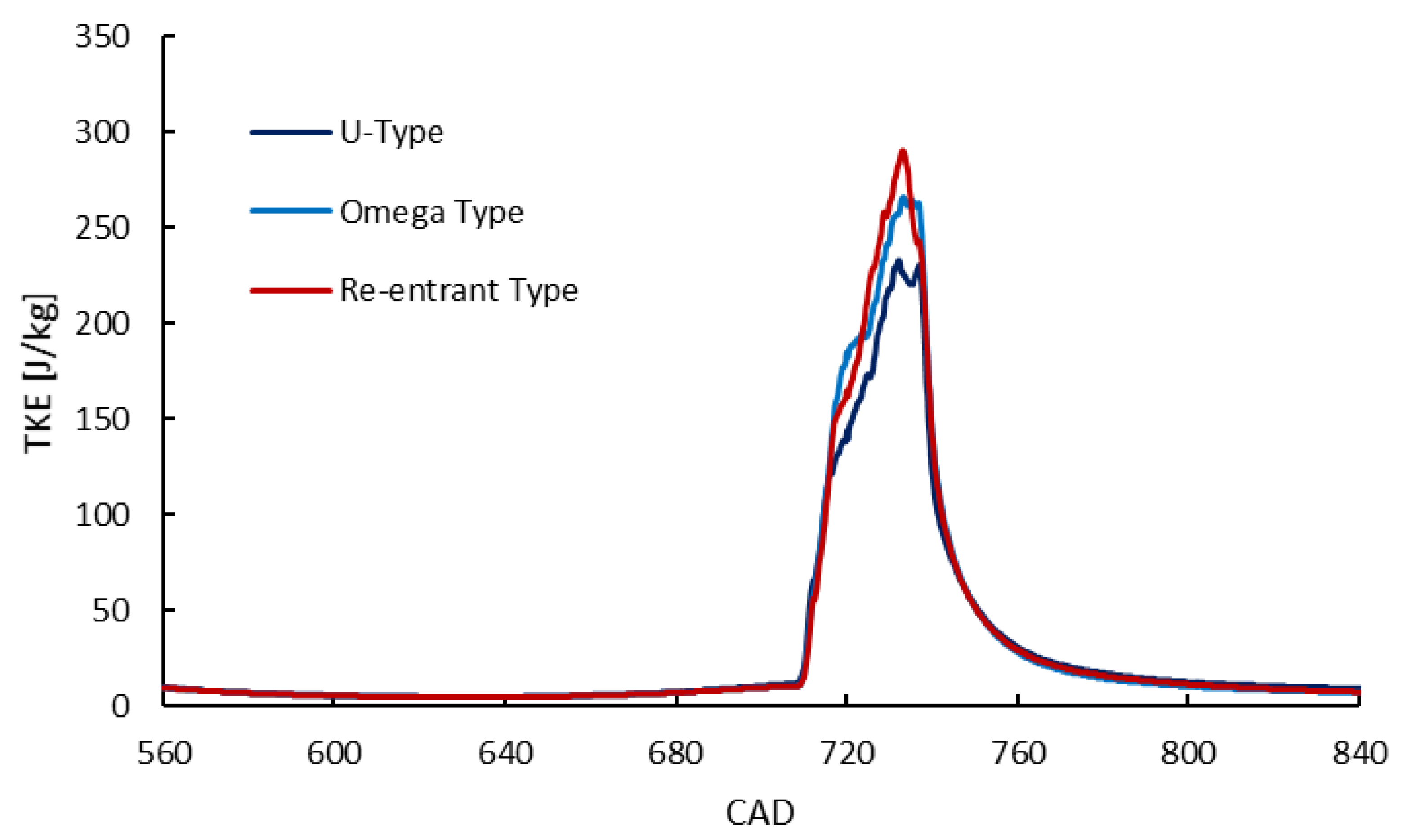
The mean TKEs of fluid flow inside the engine cylinder for the three piston bowl types are presented in
Figure 6. The computed results pointed out that the TKE of the flow in the engine cylinder when using the re-entrant and ω-type piston bowls was higher than that of the U-type bowl, and the re-entrant type of bowl produced the highest TKE. This means that the re-entrant piston bowl produced a higher flow turbulence intensity compared to the ω-type and originally designed U-type bowls. This is because the inclined surfaces along with the circular corners on the piston surfaces of the ω-type and re-entrant piston bowls created more vortices (turbulence) inside the engine combustion chamber than in the originally designed U-type piston bowl when the fuel was directly injected into the engine cylinders. The increase in TKE enhances the mixing quality between the injected fuel and in-cylinder air, which improves the combustion quality and thus engine performance [
17,
18,
19,
20,
22,
25,
26,
28,
30].
3.2. Temperature Inside Engine Cylinder
The temperature distributions within the engine cylinder at some CADs, where the highest temperature occurred owing to fuel combustion, are shown in
Figure 7. From the temperature distributions, it is clearly seen that the
-type and re-entrant piston bowls reduced the in-cylinder peak temperature. The re-entrant piston bowl produced the lowest peak temperature, which significantly and directly influences NO emission formation inside the engine cylinder. In addition, it is interesting to see that the temperature was more uniformly distributed in the case of using the re-entrant piston bowl. It is this that reduced the peak temperature in the engine cylinder.
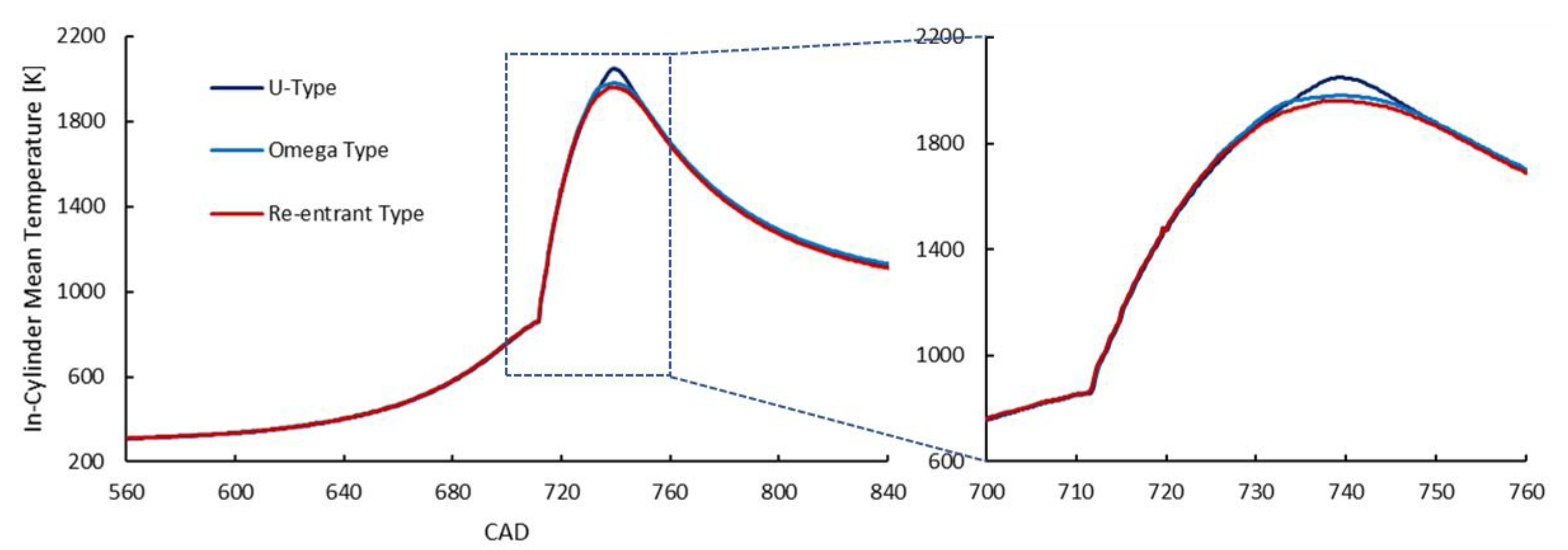
As presented in
Section 3.1, the inclined surfaces, along with the circular corners on the piston surfaces of the ω-type and re-entrant piston bowls, created more vortices inside the engine combustion chamber. This led to higher TKEs in the case of using these types of piston bowls compared to the original U-type piston bowl of the engine. Higher TKEs helped to distribute the temperature inside the engine cylinder more uniformly, as presented in
Figure 7. A decrease in the in-cylinder peak temperature due to a more uniform temperature distribution was also reported by Antunes et al. in their study [
53].
Figure 8 presents the in-cylinder temperature diagrams for the three types of piston bowls. The reduction in peak temperature along with a more uniform temperature distribution inside the engine cylinder when using the ω-type and re-entrant piston bowls reduced the in-cylinder mean temperature.
3.3. In-Cylinder Pressure and Rate of Heat Release (RoHR)
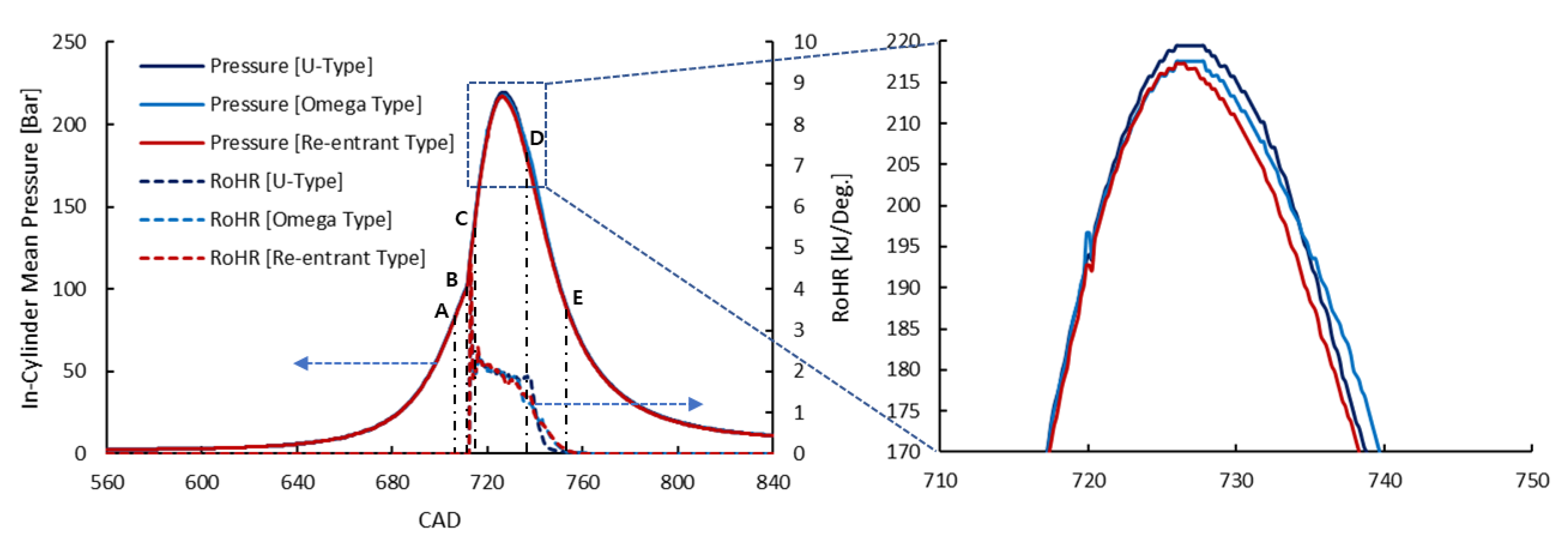
The mean in-cylinder pressure and RoHR diagrams for the three various piston bowl types are presented in
Figure 9. The results pointed out that, even though the in-cylinder peak pressure insignificantly changed when changing the type of piston bowl, it slightly decreased in the order of the U-type,
-type, and re-entrant type of the engine piston bowls.
The decrease in peak pressure in the engine cylinder has the same cause as the decrease in the peak temperature in the cylinder. The more uniform distribution of temperature (thermal energy) within the engine combustion chamber decreased the peak combustion pressure of the engine cylinder. However, it should be noted that a decrease in in-cylinder peak pressure does not imply that engine power will also be reduced. This is because of the following reason:
The effective work generated by the cylinder in a working cycle (
) of the engine is calculated by Formula (2):
where
are the in-cylinder pressure and the cylinder volume of the engine, respectively.
are the clearance volume and overall volume of the cylinder, respectively.
is a sum of
and the swept volume
.
In Formula (2),
is the work carried out during the combustion and expansion strokes of the engine when the piston moves downward from the TDC to the bottom dead center (BDC). Meanwhile,
is the work consumed to force the piston to move upward from the BDC to the TDC (including all the compression stroke and one part of the combustion stroke when the piston has not passed TDC). The consumed work in a diesel cycle is thus not only the work for the compression process, but also the work consumed to counteract the resistance of the expansion of the combustion gas inside the engine cylinder when the combustion occurred, but the piston has not passed TDC yet. Generally, higher peak pressures could increase the work of the combustion and expansion processes. However, the cycle work of the cylinder may not change or even decrease, even if the peak pressure in one case is higher than the pressure in another case if the work consumed to force the piston to move up from BDC to TDC in this is also higher. A comparison of the cylinder power and indicated specific fuel oil consumption (ISFOC) when using the three types of piston bowls is shown in
Section 3.4.
The RoHR history in
Figure 9 clearly presents the four stages of combustion of the engine. This is a DI diesel engine. In all three cases, the combustion of the engine undertook four stages, including the (1) 1st stage–ignition delay stage (ID); (2) 2nd stage–premixed combustion stage; (3) 3rd stage–diffusion combustion stage; and (4) 4th stage–late stage of combustion. The 1st stage began when the fuel was injected directly into the engine cylinder (point A) and finished when the fuel self-ignited (point B). In this stage, the RoHR was zero due to the fuel being under the heat-receiving process for heating and evaporation to prepare for self-ignition. The 2nd stage began immediately after the self-ignition of the fuel (point B) until the pre-mixed mixture between the fuel injected into the cylinder during the ID time with the charge air finished (point C). In this stage, thermal energy (heat) from the premixed combustion was rapidly released in a very short time leading to a very high RoHR, as shown in
Figure 9. At the moment when the combustion of the mixture ended (point C), diffusion combustion began. This 3rd stage took place until the end of fuel injection (point D). During this stage, the injected fuel was burnt immediately after being injected into a very high-temperature environment inside the engine cylinder caused by the premixed combustion. This combustion stage usually takes place in a relatively stable manner, resulting in a stable RoHR as shown in
Figure 9. After the fuel injection ended (point D), the 4th stage of combustion began. This late stage of combustion took place until all the remaining fuels inside the engine cylinder were completely burnt (point E). During this stage, due to the remaining fuel inside the engine cylinder being proportionally decreased with time, the RoHR was also reduced to zero when all the remaining fuels were burnt completely.
The RoHR diagrams also showed that, in all three cases of the piston bowl type, the RoHR was almost the same in the 1st to 3rd stages of combustion. However, in the 4th stage, the late combustion stage, the RoHR in the U-type piston bowl case dropped slightly faster than in the other two cases. This is possibly owing to the higher temperature inside the engine cylinder, in the case of the U-type piston bowl (as presented in
Figure 8), hastening the chemical reaction that causes the fuel to burn out faster in the late combustion stage of the engine.
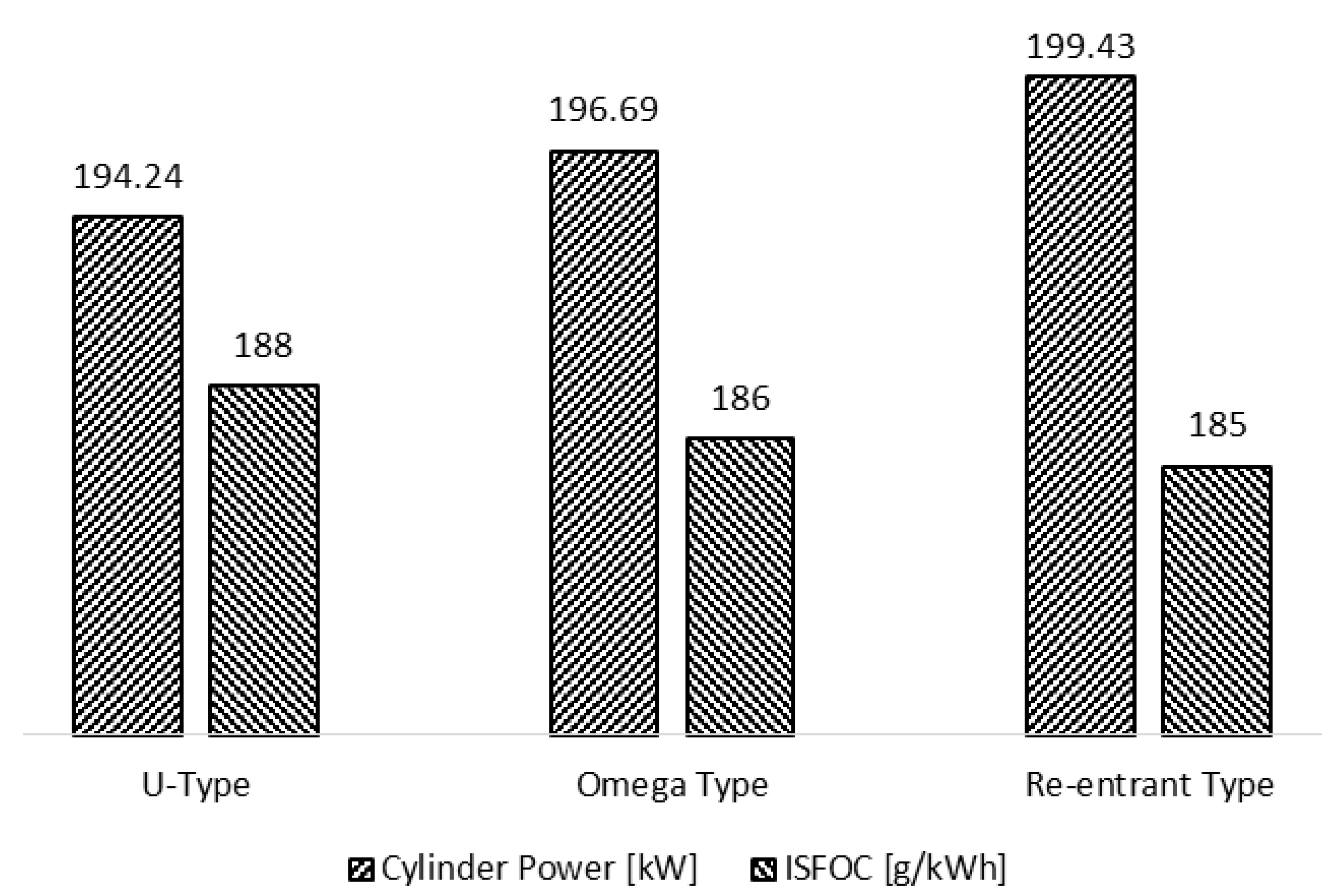
3.4. Engine Performance and Specific Fuel Oil Consumption
Figure 10 presents a comparison of cylinder power and ISFOC when using the three types of piston bowls. It is clear that the cylinder power increased when using the
-type and re-entrant piston bowls instead of the U-type bowl. Because the injected fuel in the three cases was kept unchanged, an increase in the cylinder power resulted in a decrease in ISFOC. Among these types of piston bowls, the re-entrant type produced the highest cylinder power and lowest ISFOC. As mentioned in
Section 3.1, the
-type and re-entrant piston bowls increased the TKE of the in-cylinder flow, leading to an increase in the fuel/air mixing quality between the injected fuel and in-cylinder air. The higher fuel/air mixing quality resulted in better combustion quality and then consequently enhanced the cylinder power.
In addition, as can be observed in
Figure 9, even though the peak pressures in the U-type and
ω-type piston bowl cases were higher than in the re-entrant piston bowl case, the in-cylinder pressures at TDC of the engine in these cases were also higher than in the re-entrant piston bowl case. This resulted in a reduction in the cycle work of the cylinder in the U-type and
ω-type piston bowl cases in comparison with the re-entrant piston bowl case, as calculated by the software based on Formula (2).
The
-type and re-entrant piston bowls increased the cylinder power by 1.26% and 2.67%, respectively, compared to the U-type bowl. Meanwhile, the ISFOC decreased by 1.06% and 1.60%, respectively, when using the
-type and re-entrant piston bowls instead of the U-type bowl. Jaichandar and Annamalai also reported in [
19] that the re-entrant bowl improved the fuel/air mixing quality, resulting in a performance improvement.
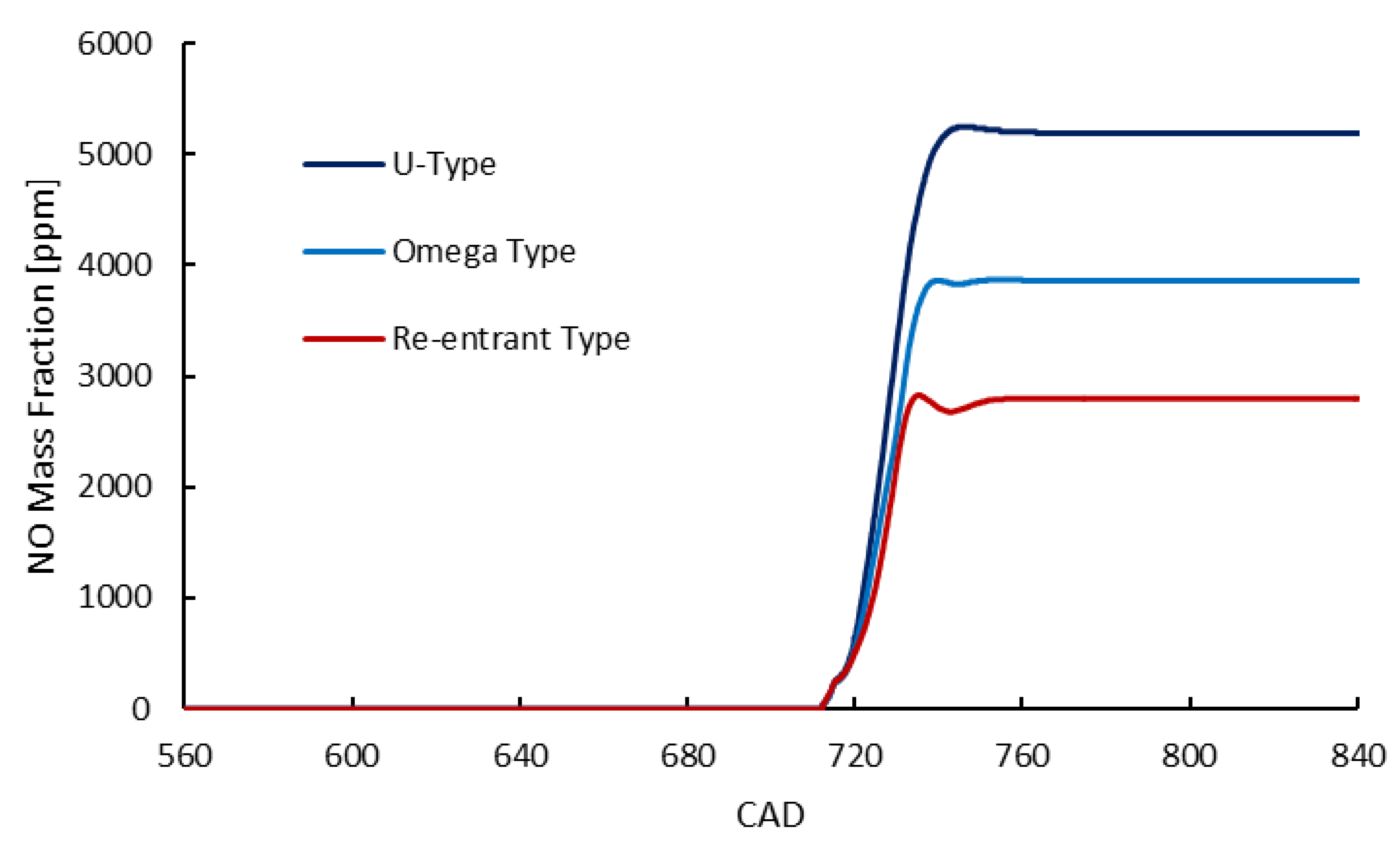
3.5. NO Emission
Figure 11 presents the NO emissions formed inside the engine cylinder in the three cases of using various piston bowls. The results pointed out that the NO emissions generated in the
-type and re-entrant piston bowl cases were remarkably reduced compared to those in the original U-type bowl. The NO emissions generated in the
-type and re-entrant piston cases were reduced by up to 25.61% and 46.09%, respectively, in comparison to the U-type piston bowl.
It is universally known that thermal NO formation is significantly and mainly influenced by the in-cylinder local maximum temperature and the oxygen (O
2) concentration in the cylinder of ICEs. NO emissions are mainly formed in regions with temperatures above 1800 K, and the rate of formation increases strongly according to the increase in temperature [
14,
40,
49].
As can be observed in the temperature distribution shown in
Figure 7, the in-cylinder peak temperatures, in the cases of using the ω-type and re-entrant piston bowls, were significantly reduced in comparison with the U-type bowl, and the re-entrant piston bowl produced the lowest peak temperature. This resulted in the lower NO emission formations in the ω-type and re-entrant piston bowls compared to the U-type bowl, especially in the re-entrant piston bowl. A better TKE and the simultaneous reduction in NOx emissions when using a re-entrant piston bowl had also been reported by Prasad et al. [
27,
28].
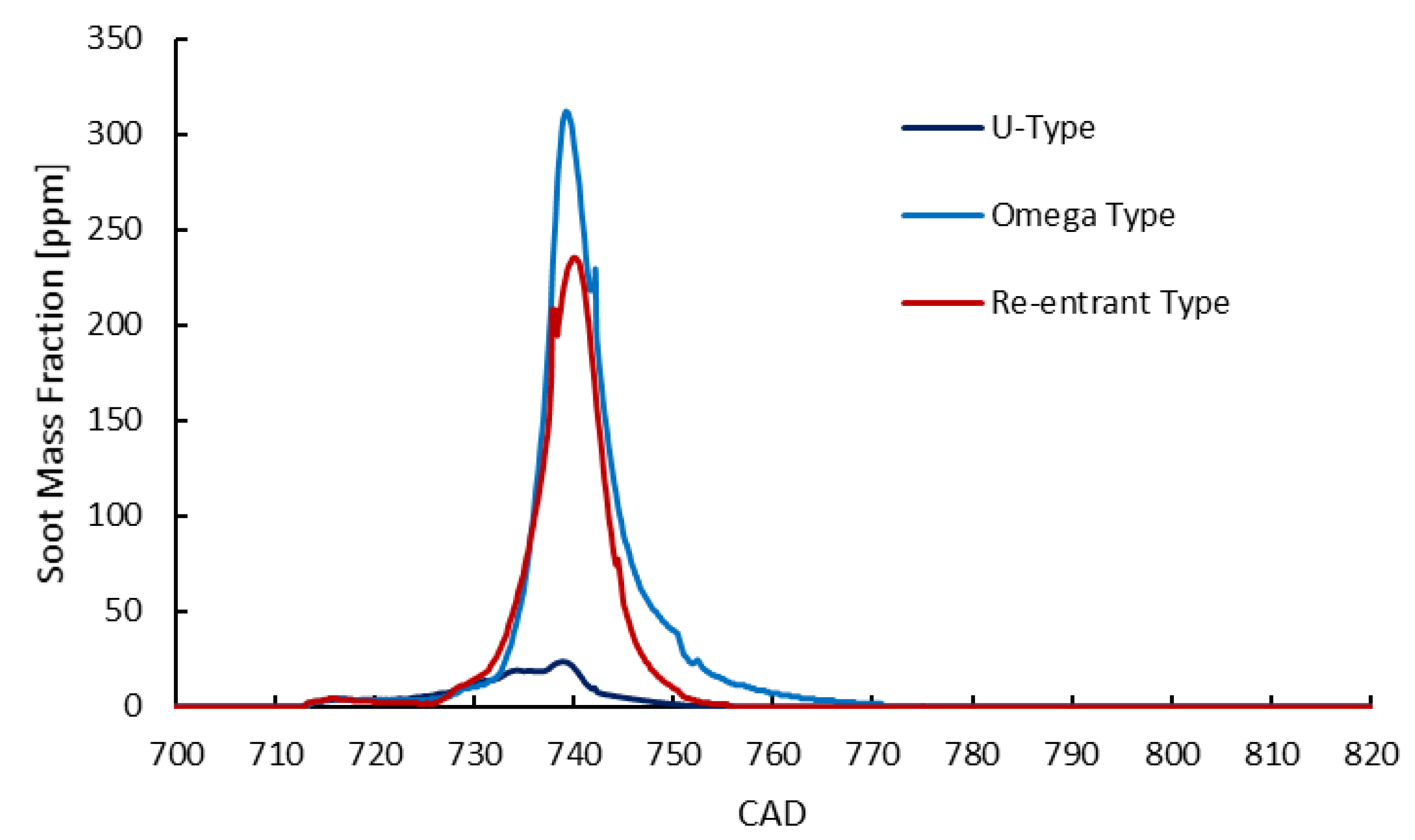
3.6. Soot Formation
Soot is the primary component of PM (particulate matter) emissions [
54,
55,
56,
57]. Under high-temperature and fuel-rich conditions (high fuel-to-air equivalence ratios), which are usually found in the combustion process of DI diesel engines, the diffusion combustion of hydrocarbon (C
xH
y) fuels produces a lot of carbonaceous particles (soot). However, under the normal working conditions of ICEs, most soot emissions formed during the diffusion combustion stage (early stage of combustion) are completely burnt, caused by its oxidation with residual O
2 in oxygen-rich regions inside the engine combustion chamber during the later stages of the fuel combustion. This means that, in fuel direct injection ICEs, their PM emission characteristics or the final engine-out amount of soot are actually determined by the completeness of the soot oxidation during the combustion process of the engine [
45].
Figure 12 presents the soot emissions formed inside the engine cylinder in the three cases of using various piston bowls. The simulation results pointed to a similar soot formation process, as presented in the literature [
45]. Specifically, soot was mainly formed very early in the diffusion combustion stage, owing to the fuel dissociations under high-temperature and high fuel/air equivalence ratio conditions inside the engine cylinder. Soot was then completely burnt due to the oxidation with residual O
2 in the engine cylinder in the later stages of the combustion. As a result, at the end of the expansion processes of the engine, the final generated soot amount was almost zero. This means that, although there were some differences in soot formation during engine combustion, the final amount of soot produced in all three piston bowl cases was roughly the same. That is, changing the type of piston bowl does not affect the engine-out soot emission characteristics of the engine.
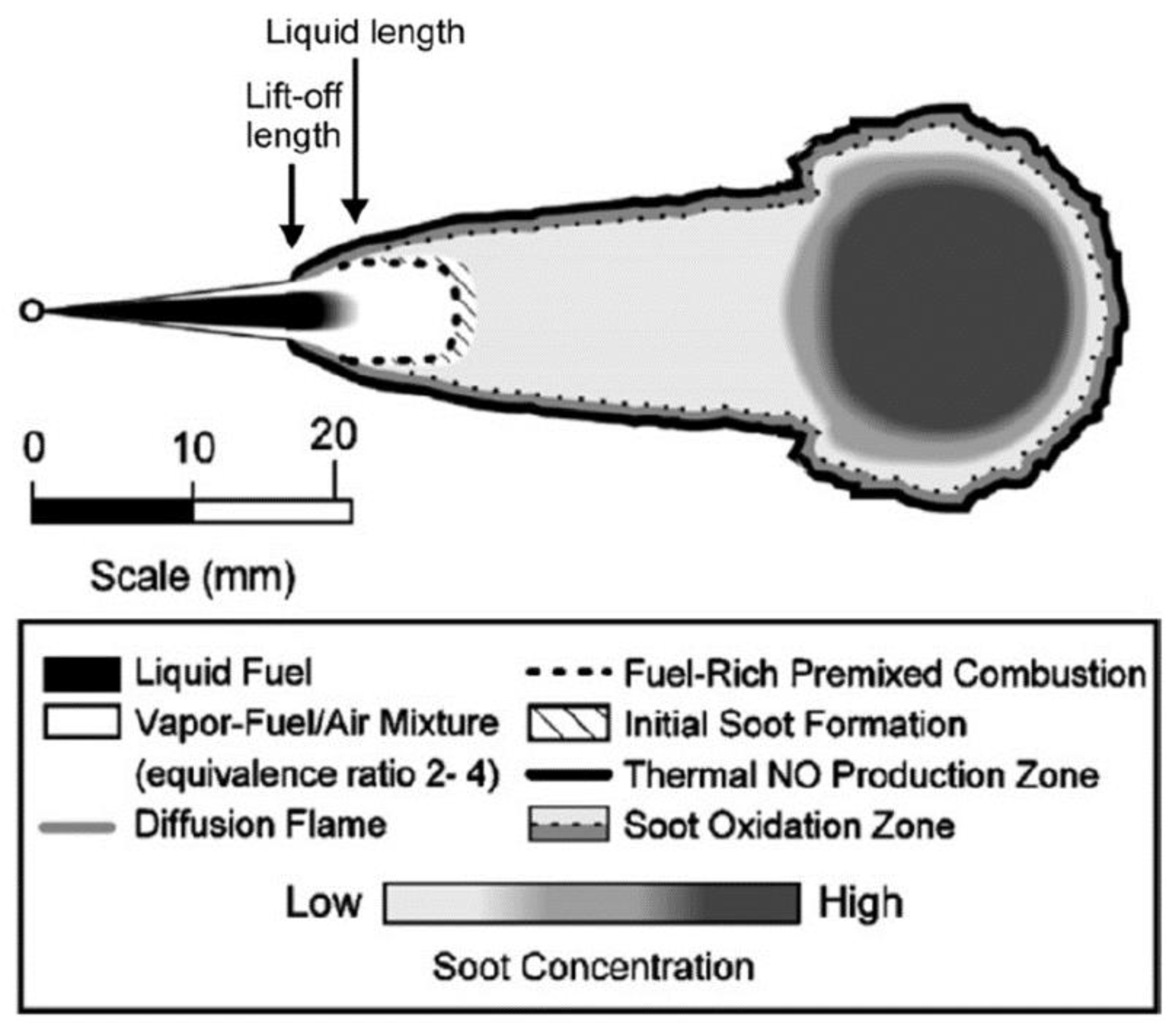
Figure 13 illustrates the soot and thermal NO zones in the injection region of DI diesel engines. As can be seen, soot is mainly formed in fuel-rich and high-temperature zones. Meanwhile, NO is strongly formed in very high-temperature zones. These results confirm the simulation results in this study.
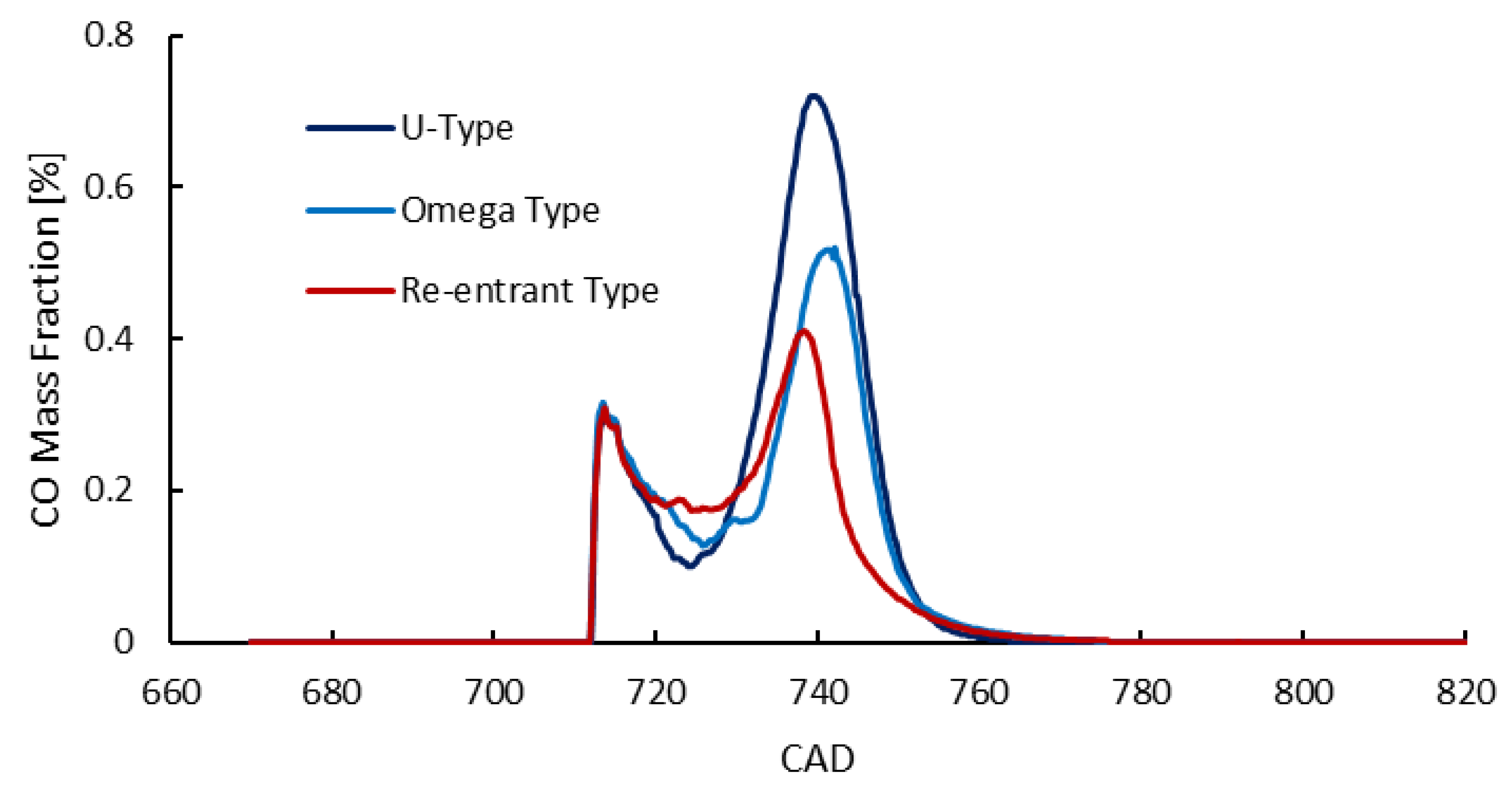
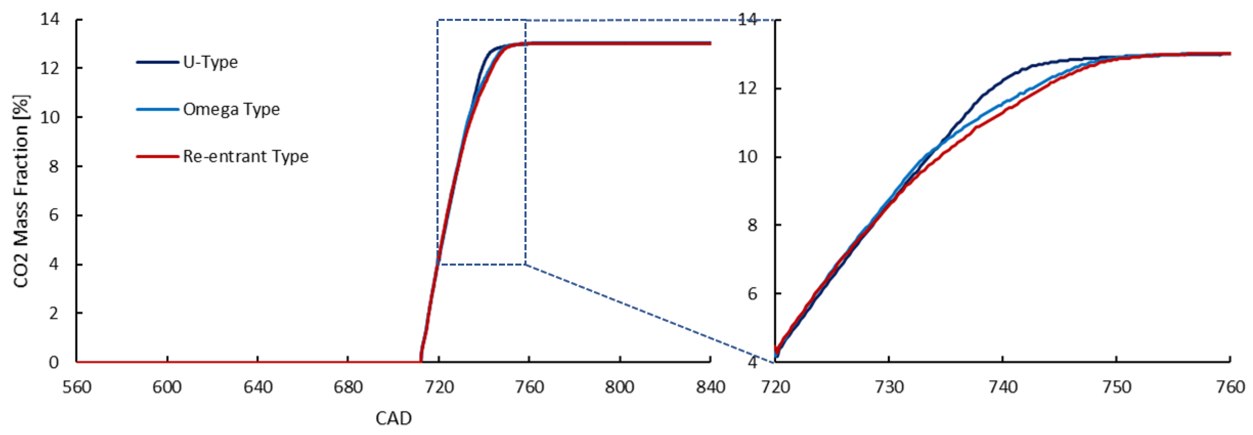
3.7. CO and CO2 Emissions
Figure 14 and
Figure 15 present the CO and CO
2 emissions formed inside the engine cylinder in the three cases of using various piston bowls, respectively. The simulation results showed significant reductions in CO formation during the combustion process of the engine in the re-entrant and
-type piston bowl cases in comparison to the U-type piston bowl case, in which the re-entrant piston bowl generated the lowest CO emission in the combustion process. The reason is because the turbulence intensities in the cylinder of the engine in the
-type, and especially in the re-entrant type of piston bowls, were higher than those in the U-type, as shown in
Figure 6. CO formation is strongly influenced by the combustion quality which is strongly affected by the fuel-air mixing quality. Higher in-cylinder turbulences result in better fuel-air mixing quality leading to a higher combustion quality and lower CO formation. However, the CO emissions at the end of the expansion process of the engine in all three piston bowl cases were almost zero because they were oxidized by the residual oxygen inside the engine cylinder to form CO
2 emissions, the complete product of hydrocarbon fuel combustions.
As is the same as in the soot characteristics of the engine, except for only a little difference in CO2 formation during the combustion of the engine, the final generated amounts of CO2 emissions when using the three piston bowl types were almost the same. This implies that changing the type of piston bowl has a negligible effect on the engine-out CO2 emission characteristics of the engine.
Observing the process of CO2 formation closely, it can be seen that the CO2 formation process in the re-entrant piston bowl case was slowest, followed by the -type piston bowl case, and the U-type bowl case created the fastest CO2 formation. This is due to differences in the in-cylinder temperature profile of the engine when using different piston bowl types. As has been known, CO2 is the final product of a complete combustion of hydrocarbons. First, hydrocarbons are oxidized by O2 to form carbon monoxide (CO). CO is then further oxidized to form CO2 in high-temperature conditions by remaining O2 inside engine cylinders. Higher in-cylinder temperatures will enhance the CO oxidation rate, or in another word, increase the CO2 formation rate. This means that CO2 formation is strongly influenced by the temperature and O2 concentration inside engine cylinders.
In ICEs, to ensure that all injected fuel is completely burned, the engines are designed to always be supplied with a larger amount of air than they need for the theoretical complete combustion of fuel. This amount of air that is more abundant than is chemically necessary for complete combustion is called air excess. The air excess ratio in diesel engines is typically about 1.6 to 2.2 [
13]. This means that there will always be enough air for fuel oxidation during the combustion process of ICEs. Excluding the O
2 concentration factor, the remaining factor affecting the formation of CO
2 is the temperature in the cylinder. As can be seen from
Figure 7 and
Figure 8, the in-cylinder temperatures, in the cases of using the
-type and re-entrant piston bowls, were lower than that when using the U-type bowl. This reduced the CO
2 formation rate in the cases of using the
-type and re-entrant piston bowls. Among these three piston bowl types, the re-entrant type had the slowest CO
2 formation rate due to its lowest in-cylinder temperature. However, finally, the amounts of CO
2 emissions generated from the three types of piston bowls were almost the same at the end of the combustions because the charged air and injected fuel amounts were the same.
4. Conclusions
In this study, the effect of piston bowl geometry on the combustion, performance, fuel oil consumption, and emission formations of a four-stroke direct injection diesel marine engine was investigated to specify the most effective geometry for the piston bowl of the engine.
The primary results of the present study are summarized below:
- (1)
The TKE of the turbulent flow in the engine cylinder when using the re-entrant and -type piston bowls was higher than that of the U-type bowl type. The re-entrant type of bowl produced the highest TKE.
- (2)
The -type and re-entrant piston bowls reduced the in-cylinder peak temperature due to more uniform temperature distributions inside the engine cylinder. The re-entrant piston bowl produced the lowest peak temperature.
- (3)
The -type and re-entrant piston bowls enhanced the cylinder power by 1.26% and 2.67%, respectively, while reducing the ISFOC of the engine by 1.06% and 1.60%, respectively, compared to the U-type bowl.
- (4)
The -type and re-entrant piston bowls reduced NO emissions by up to 25.61% and 46.09%, respectively, in comparison to the U-type piston bowl.
- (5)
For soot and CO2 emissions, the computed results pointed out that changing the type of piston bowl has a negligible effect on the engine-out soot and CO2 emission characteristics of the engine.
Based on the results of this study, it is highly recommended to use the re-entrant piston bowl for four-stroke direct injection diesel engines because it not only improves engine performance and fuel oil consumption, but also decreases NO emissions. In another word, this type of piston bowl helps to enhance both economic and environmental benefits. As the spray angle of the fuel injector of direct injection ICEs has an influence on the squish flow inside the engine cylinder, which affects in-cylinder air-fuel mixing quality, further investigations on the combined effects of piston bowl geometry along with injector spray angle should be performed in future works.


 ,
, 


