Article

Improving the Performance of an Ultrashort Soft X-ray Free-Electron Laser via Attosecond Afterburners

1
Shanghai Institute of Applied Physics, Chinese Academy of Sciences, Shanghai 201800, China
2
University of Chinese Academy of Sciences, Beijing 100049, China
3
Shanghai Advanced Research Institute, Chinese Academy of Sciences, Shanghai 201210, China
4
State Key Laboratory of Nuclear Physics and Technology and Institute of Heavy Ion Physics, School of Physics, Peking University, Beijing 100871, China
5
School of Physical Science and Technology, ShanghaiTech University, Shanghai 201210, China
6
Institute of Advanced Science Facilities, Shenzhen 518000, China
*
Author to whom correspondence should be addressed.
Appl. Sci. 2022, 12(22), 11850; https://doi.org/10.3390/app122211850
Submission received: 21 August 2022 / Revised: 23 October 2022 / Accepted: 15 November 2022 / Published: 21 November 2022
(This article belongs to the Special Issue Recent Advances and Applications in X-ray Free-Electron Lasers)

Abstract

:
In this study, we implement attosecond afterburners in an ultrashort soft X-ray free-electron laser (FEL) to improve the performance of generating attosecond pulses. In this scheme, the FEL pulse produced in the normal radiator section is dumped while the well bunched electron beam is reserved and reused in downstream afterburners. Subsequently, radiation in the afterburners gains rapidly as the bunching factor in the current spike is large, making the radiation pulse much shorter and cleaner than that from a normal radiator. Multi-shot simulations are carried out to demonstrate the performance and stability of the proposed technique.

1. Introduction

In molecular systems, electron dynamics occur on a timescale in the order of a few hundred attoseconds. Light pulses on this timescale and of certain demanded qualities are necessary in many research areas such as measurement technology, studying molecular structure, and capturing multielectron dynamics [1,2,3,4]. Laser pulses in the water window can penetrate through the solution and can only react to common elements in biomolecules. Hence, the generation of attosecond laser pulses in the water window has become a frontier in many research fields [5,6,7]. High-harmonic generation (HHG) [8] holds the capability of producing attosecond pulses. During the past 20 years, the HHG technique has been significantly improved, through which the wavelength has been extended to the soft X-ray range, and the pulse duration can be as short as 50 as [9,10,11]. However, the pulse energies of HHG are usually limited to the picojoule level. An X-ray free-electron laser (XFEL) [12] is distinguished for its high intensity and flexible control of various output properties [13]. Most FEL facilities currently in operation are based on the self-amplified spontaneous emission (SASE) principle [14]. The output of SASE is usually characterized by large shot-to-shot fluctuations [15,16] and the pulse durations are generally determined by the electron bunch length. In order to shorten pulse durations, several methods have been developed [17,18,19,20,21,22,23,24,25,26]. Among them, the enhanced self-amplified spontaneous emission (ESASE) technique [18] has been experimentally demonstrated to be able to generate attosecond FEL pulses in the soft X-ray range [27,28,29,30]. The ESASE technique has also been considered by many other FEL facilities [31,32,33,34,35].
In this paper, we propose to implement short afterburners following an ESASE scheme to further shorten the pulse duration and to improve the stabilities of the attosecond pulses. Similar methods have been employed in the chirp-taper scheme to generate attosecond pulses in the EUV and soft X-ray regions [36]. In this work, microbunching in the electron beam is generated through the ESASE process. Radiation from ESASE is dumped, while the well bunched electron beam is reserved and reused in the downstream afterburners to produce attosecond pulses. We perform detailed numerical simulations and the results show that the pulse duration can be shortened by half, while the peak power can be well maintained. In addition, pulse duration and intensity stabilities can also be improved as compared with the conventional ESASE process.

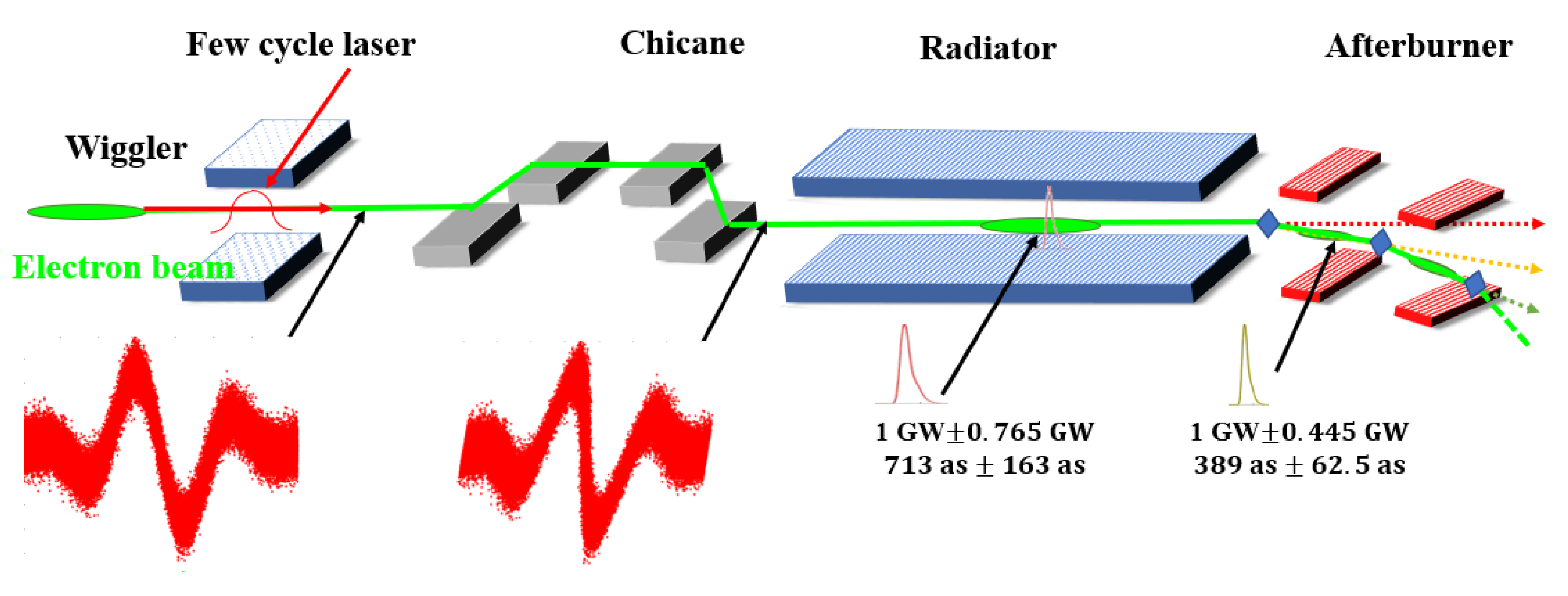
2. Layout for the Proposed Technique

The layout of the proposed technique is shown in Figure 1. The whole beamline consists of a normal ESASE section followed by a series of afterburners. Similar to the conventional ESASE process [18], first, a few-cycle laser pulse is employed to interact with the electron beam in a short modulator (wiggler) to introduce energy modulation [37,38]. Then, energy modulation is converted into density modulation by using a small chicane to increase the peak current in a small fraction of the electron beam. The FEL radiation is amplified and the electron beam is well bunched in the radiator. The shortest pulse duration is limited by the FEL slippage in the radiator [24], which is in the femtosecond range for a soft X-ray FEL. To overcome this limitation, afterburners are added after the radiator. Intense attosecond pulses can be obtained with very short undulators with the well bunched electron beam. Otherwise, since the FEL in the afterburners is generated from bunched electron beam other than random noises, the stabilities of both the power and the pulse duration are expected to be improved. Quadrupoles with transverse offsets are added between the radiator and afterburners to kick the electron beam and to split the attosecond pulses from different undulators [39].

3. Numerical Simulations

Three-dimensional simulations are employed to illustrate the performances of the proposed technique. Typical parameters of a soft X-ray FEL facility are chosen to perform these simulations, as shown in Table 1. The processes of energy modulation in the wiggler and the transmission processes in the chicane are simulated with FALCON [40] and ELEGANT [41]. The processes of FEL lasing are simulated with GENESIS [42].
The initial electron beam is assumed to have an energy of 2.5 GeV, an energy spread Δσ of 0.25 MeV, an average beam radius of 30 μm (rms), an emittance of 0.4 μm (rms), and a peak current of 800 A. The few-cycle modulation laser pulse employed in the wiggler is about 8 fs (FWHM) with a central wavelength of λ 0   = 2400 nm, a power of 40 GW, and a radius of 0.4 mm. The periods for both the radiator and the afterburners are chosen to be the same value of λ 1   = 3 cm. The central wavelength of the FEL is 3 nm.

3.1. Modulation before the Radiator

The initial phase space of the electron beam is shown in Figure 2a. Modulated by a few-cycle laser in the wiggler, energy modulation is imprinted on the longitudinal phase space of the electron beam, as shown in Figure 2b. The laser-induced energy modulation amplitude is A = ∆γ/Δσ = 12. After passing through a chicane with an optimized strength of R56 = 0.75 mm [29,35], energy modulation is transformed into density modulation, as shown in Figure 2c. Figure 2d presents the current profile after the chicane with a peak current of about 4800 A.
The electron beam with an enhanced current spike is sent into a radiator resonant at 3 nm. The simulation results for the evolutions of the FEL peak power and the pulse duration along the radiator are summarized in Figure 3a. The peak power keeps increasing in the 21 m long radiator, while the pulse duration fluctuates from 500 as to 1400 as, due to the slippage effect. To obtain profound insight into the influence of the slippage effect, the evolution of the FEL pulse along the radiator is plotted in Figure 3b. In the radiator, the FEL pulse slips ahead by about 1.7 fs for every 5 m with respect to the current peak. This slippage causes a decrease in the gain of the main pulse with a decline in the local current. With a sufficiently large bunching factor in the current peak, new pulses are continually generated, resulting in a large fluctuation of the pulse duration in the radiator.

3.2. FEL Evolution in the Radiator

To further analyze the bunching properties of the electron beam in the radiator, the evolutions of the local bunching factor at the main current peak and the maximum bunching factor along the electron beam are given in Figure 3c. It can be observed that the local bunching factor at the main current peak increases along the radiator and reaches 35% at around 20 m. Due to the slippage effect, the FEL pulse moves forward and interacts with a fresh fragment of the electron beam, resulting in a much larger bunching factor of about 75% at 20 m. Figure 3d gives the profiles of the bunching factor along the electron bunch at 16 m and 20 m of the radiator. The peaks of the bunching factor moved ahead by about 1 fs (16 m) and 2 fs (20 m), respectively. Although the maximum bunching factor at 20 m is larger than that at 16 m, the multi-peak bunching profile will degrade the performance of the FEL in the following afterburner.

3.3. Optimization of the Lengths of the Undulators

After passing through the radiator, the well bunched electron beam is sent into the afterburner to lase again. According to Figure 3b, the bunching factor increases along the radiator of the ESASE section, giving rise to higher power in the afterburner. However, with an increased length of the radiator, the duration of the bunching profile is also increased, and the signal to noise ratio is dramatically decreased, as shown in Figure 3d. To achieve radiation pulse with high intensity and short duration, the lengths of the radiator (z1) and the afterburner (z2) need to be optimized. Simulations are performed for different cases and the results are presented in Figure 4. When z1 is constrained to 14 m < z1 < 16 m, the peak power from the afterburner can be over 1 GW and the pulse duration can be less than 400 as, with a proper length of the afterburner (0.6 m < z2 < 1 m). In the following simulations, the length of the radiator and the afterburner is chosen to be 14.76 m and 0.72 m, respectively.
The power of the superradiance generated with the pre-bunched electron beam is proportional to the product of the beam current squared and the bunching factor squared: P∝ I 2 b 2 [43,44]. The duration of the output pulse from the radiator is about 700 as, as shown in Figure 5a. In comparison, Figure 5a also shows the profiles of the current peak, bunching factor, and the I 2 b 2 by the end of the radiator. Although the duration of the current peak and the bunching profile is 600 as and 1 fs, correspondingly, the distance between them leads to a much shorter duration of about 350 as compared with the I 2 b 2 profile. Driven by the large bunching factor, intense radiation is immediately generated at the beginning of the afterburner. Figure 5b shows the radiation pulse from the afterburner, where the pulse duration is 396 as and the peak power is 1.47 GW.

3.4. Simulations of the Kickers

Now, we show an example of the performance of the first afterburner and the second afterburner, to illustrate the subtle influence of the kick, which is induced by a quadrupole with a transverse offset. The parameters of the two kickers are the same, as shown in Table 1. The length of the radiator is chosen to be 14.76 m. The lengths of both the first and the second afterburner is chosen to be 1.71 m for simplicity. The electron beam is kicked by 15 μRad, after traveling through a quadrupole of 0.1 m long, with a focal length of 10 m, and an offset in the y axis of 30 μm. The axial displacement between the laser in the radiator and the laser after the kicker can be approximately calculated to be ∆y = 15 μRad × 10 m = 150 μm, which is twice the RMS radius of the electron beam. The simulation results of this part are depicted in Figure 6.
As can be seen in Figure 6a, the decrease in the bunching factor profile at the kicker between the radiator and the afterburner is less than 10% at the main current peak. Then, in Figure 6b, in the first afterburner, the FEL grows slower than that in Figure 4, but still reaches 1 GW at 0.96 m with a pulse duration of 401 as. Figure 6c shows the change in the bunching factor profile at the second kicker. The overall bunching factor grows to a higher level than that in Figure 6a. Figure 6d shows the performance of the FEL in the second afterburner. The FEL reaches 1 GW at 0.66 m, with a pulse duration of 318 as.

3.5. Stability against the SASE Fluctuation

To analyze the stability of the proposed technique, multiple runs of the simulation are carried out with different shot noise initializations [39]. As we have mentioned above, the output properties of the SASE-based FEL can fluctuate a lot from shot-to-shot. According to Figure 3a, the different gain processes of ESASE also result in different output pulse durations. However, radiation in the afterburner, which is determined by I 2 b 2 , only occurs in the region where the current and bunching factor are relatively large, making the pulse duration nearly immune to the slippage effect in the ESASE radiator. The statistics of the evolutions of peak power and pulse duration are shown in Figure 7, where one can find that both the power and pulse duration jitters in the afterburner are much smaller than those in the radiator. The average peak powers reach 1 GW at about 13.65 m of the radiator and about 0.72 m of the afterburner.
Figure 8 shows the simulation results of the FEL peak power and pulse duration at 13.65 m in the radiator and 0.72 m in the afterburner. The Gaussian fits are given to depict the distribution of peak power and pulse duration of the whole 280 shots. The standard deviations of the peak power and the pulse duration are 0.765 GW and 163 as in the radiator while 0.445 GW and 62.5 as in the afterburner, respectively, as shown in Figure 8. These results demonstrate that the stabilities of the FEL pulses from afterburner can be well improved due to the utilizing of pre-bunched electron beams.

3.6. Effect of Longitudinal Space Charge

It has been pointed out that the longitudinal impedance and wake from undulators can significantly affect the performances of current-enhanced SASE schemes [45]. The energy chirp induced by the longitudinal space charge (LSC) field can be estimated [45,46] by E z Z 0 I s 4 π γ z ¯ 2 2 ln γ z ¯ σ z r b + 1 r 2 r b 2 , where Z 0 = 377 Ω , I s = d I / d s is the derivative of the longitudinal current distribution with respect to the bunch coordinate s, γ z ¯ = γ / 1 + K 2 , σ z is the rms bunch length of the current peak, and r b is the beam radius of a uniform transverse distribution. Here, we take γ z ¯ = 2236 , and the central spike σ z = 51 nm. Figure 9 shows the accumulated energy modulation due to the LSC effect at a distance of 14.76 m in the FEL undulator. For the central current spike, a strong energy chirp with a peak-to-peak energy variation of about 24 MeV is produced by the LSC effect. Such a large energy spread is much larger than the FEL bandwidth, and can degrade the FEL interaction. However, it has been pointed out in [46] that a properly tapered undulator can compensate for the FEL gain degradation induced by a linearly chirped electron beam. The effectiveness of undulator tapering on compensating the FEL power loss has also been confirmed theoretically [27,46] and experimentally [28,47].
To compensate for the energy loss of the FEL due to the LSC effect, tapers should be applied in the undulators according to [48]. A linear taper of 0.61% is adopted in the radiator, and the length of the radiator remains to be 14.76 m. At the end of the radiator, the local bunching factor at the peak current is about 0.12, still large enough to initiate coherent radiation in the following afterburner.
The performance of the FEL in the afterburner is shown in Figure 10. The peak power can still reach 1 GW in the afterburner. The pulse profile at 1.47 m in the afterburner is shown in Figure 10b, where the pulse duration is about 420 as, still much shorter than that in the radiator. Comparing these results with Figure 6, the pulse durations at 1 GW power level are similar. The only difference is that the length of the afterburner needs to be extended to obtain the same peak power when the LSC is considered.

4. Conclusions

In conclusion, in this study, we demonstrated that some properties of the ESASE process can be improved by using attosecond afterburners. The simulation results show that this method can produce FEL pulses with a pulse duration of 389 as and a peak power of 1 GW, while the pulse duration in the conventional ESASE process is 720 as. In addition, simulations were also performed to verify the superior stabilities of attosecond afterburners against SASE fluctuation as compared with the conventional ESASE process. The results indicate that the fluctuations of the output pulse duration and peak power from the attosecond afterburner is about half of that in the conventional ESASE process. The optimizing methods and the results demonstrated here are also applicable to other soft X-ray FELs with similar parameters. In practical operation, a reverse-tapered radiator [49] can be applied upstream of the afterburner, producing attosecond pulses with minimal background. The radiator may be at a harmonic enabling two color pulses, that could be recombined on a sample, proper selection of the recombination beam paths could allow time coincidence, or even allow some delay scan capabilities. In this paper, we took ESASE as an example to show the performance of the proposed technique. It should be highlighted that the proposed technique is also suitable for other SASE-based ultrafast FEL generation schemes, such as emittance spoiler [17], nonlinear bunch compression [24], and fresh-slice [25] based methods. A proof-of-principle experiment for the attosecond afterburner is under preparation at the Shanghai soft X-ray FEL facility (SXFEL) [50]. Studies with the realistic parameters of the SXFEL and considering various three-dimensional effects, such as LCS in undulators, are ongoing.

Author Contributions

Conceptualization, S.Z. and C.F.; methodology, L.T., C.F., and Z.W.; software, X.W., H.S., W.F., and Y.L.; validation, C.F. and Z.Z.; formal analysis, L.T. and X.W.; investigation, L.T. and C.F.; resources, C.F. and Z.W.; data curation, X.W.; writing—original draft preparation, L.T.; writing—review and editing, L.T., Z.W., Z.Q., S.Z., and C.F; visualization, L.T. and S.Z.; supervision, Z.W. and Z.Z.; project administration, C.F. and Z.Z.; funding acquisition, Z.W., C.F., and Z.Z. All authors have read and agreed to the published version of the manuscript.

Funding

This work was supported by the National Natural Science Foundation of China (12122514 and 11975300) and the Shanghai Science and Technology Committee Rising-Star Program (20QA1410100).

Institutional Review Board Statement

Not applicable.

Informed Consent Statement

Not applicable.

Data Availability Statement

Not applicable.

Acknowledgments

We would like to thank Kaiqing Zhang and Li Zeng for useful discussions and help in the simulations.

Conflicts of Interest

The authors declare no conflict of interest.

References

  1. Corkum, P.B.; Krausz, F. Attosecond science. Nat. Phys. 2007, 3, 381–387. [Google Scholar] [CrossRef]
  2. Kasmi, L.; Lucchini, M.; Castiglioni, L.; Kliuiev, P.; Osterwalder, J.; Hengsberger, M.; Gallmann, L.; Krüger, P.; Keller, U. Effective mass effect in attosecond electron transport. Optica 2017, 4, 1492–1497. [Google Scholar] [CrossRef] [Green Version]
  3. Ayuso, D.; Palacios, A.; Decleva, P.; Martín, F. Ultrafast charge dynamics in glycine induced by attosecond pulses. Phys. Chem. Chem. Phys. 2017, 19, 19767–19776. [Google Scholar] [CrossRef]
  4. Agueny, H. Coherent electron displacement for quantum information processing using attosecond single cycle pulses. Sci. Rep. 2020, 10, 21869. [Google Scholar] [CrossRef] [PubMed]
  5. Liu, H.; Feng, L.; Qiao, Y.; Li, Y. Controlling three-step harmonic emission for intense attosecond pulses using water window harmonic spectra. J. Mod. Opt. 2022, 68, 267–275. [Google Scholar] [CrossRef]
  6. Perry, C.F.; Jordan, I.; Zhang, P.; von Conta, A.; Nunes, F.B.; Wörner, H.J. Photoelectron Spectroscopy of Liquid Water with Tunable Extreme-Ultraviolet Radiation: Effects of Electron Scattering. J. Phys. Chem. Lett. 2021, 12, 2990–2996. [Google Scholar] [CrossRef] [PubMed]
  7. Jordan, I.; Huppert, M.; Rattenbacher, D.; Peper, M.; Jelovina, D.; Perry, C.; von Conta, A.; Schild, A.; Wörner, H.J. Attosecond spectroscopy of liquid water. Science 2020, 369, 974–979. [Google Scholar] [CrossRef]
  8. Hentschel, M.; Kienberger, R.; Spielmann, C.; Raider, G.A.; Milosevic, N.; Brabec, T.; Corkum, P.; Heinzmann, U.; Drescher, M.; Krausz, F. Attosecond metrology. Nature 2001, 414, 509–513. [Google Scholar] [CrossRef]
  9. Li, J.; Lu, J.; Chew, A.; Han, S.; Li, J.; Wu, Y.; Wang, H.; Ghimire, S.; Chang, Z. Attosecond science based on high harmonic generation from gases and solids. Nat. Commun. 2020, 11, 2748. [Google Scholar] [CrossRef]
  10. Ren, X.; Li, J.; Yin, Y.; Zhao, K.; Chew, A.; Wang, Y.; Hu, S.; Cheng, Y.; Cunningham, E.; Wu, Y.; et al. Attosecond light sources in the water window. J. Opt. 2018, 20, 023001. [Google Scholar] [CrossRef]
  11. Teichmann, S.M.; Silva, F.; Cousin, S.L.; Hemmer, M.; Biegert, J. 0.5-keV soft X-ray attosecond continua. Nat. Commun. 2016, 7, 11493. [Google Scholar] [CrossRef] [PubMed] [Green Version]
  12. Saldin, E.; Schneidmiller, E.; Yurkov, M. Statistical properties of radiation from VUV and X-ray free electron laser. Opt. Commun. 1998, 148, 383–403. [Google Scholar] [CrossRef] [Green Version]
  13. Huang, Z.; Kim, K.J. Review of X-ray free-electron laser theory. Phys. Rev. Spec. Top.-Accel. Beams 2007, 10, 034801. [Google Scholar] [CrossRef]
  14. Kondratenko, A.M.; Saldin, E.L. Generating of coherent radiation by a relativistic electron beam in an ondulator. Part. Accel. 1980, 10, 207–216. [Google Scholar] [CrossRef]
  15. Thompson, N.R. Possible Method for the Control of SASE Fluctuations. Pulse 2018, 10, 10–12. [Google Scholar] [CrossRef]
  16. Yu, L.H.; Krinsky, S. Analytical theory of intensity fluctuations in SASE. Nucl. Instrum. Methods Phys. Res. Sect. A Accel. Spectrometers Detect. Assoc. Equip. 1998, 407, 261–266. [Google Scholar] [CrossRef] [Green Version]
  17. Emma, P.; Bane, K.; Cornacchia, M.; Huang, Z.; Schlarb, H.; Walz, D. The Emittance Spoiler Foil: A Simple Method to Produce Femtosecond and Sub-Femtosecond X-ray Pulses from a SASE-Based Free-Electron Laser. 2004. Available online: https://www-ssrl.slac.stanford.edu/content/sites/default/files/documents/science-highlights/pdf/fsec-200402.pdf (accessed on 20 August 2022).
  18. Zholents, A.A. Method of an enhanced self-amplified spontaneous emission for X-ray free electron lasers. Phys. Rev. ST Accel. Beams 2005, 8, 040701. [Google Scholar] [CrossRef] [Green Version]
  19. Wang, Z.; Feng, C.; Zhao, Z. Generating isolated terawatt-attosecond X-ray pulses via a chirped-laser-enhanced high-gain free-electron laser. Phys. Rev. Accel. Beams 2017, 20, 040701. [Google Scholar] [CrossRef] [Green Version]
  20. Reiche, S.; Musumeci, P.; Pellegrini, C.; Rosenzweig, J. Development of ultra-short pulse, single coherent spike for SASE X-ray FELs. Nucl. Instrum. Methods Phys. Res. Sect. A Accel. Spectrometers Detect. Assoc. Equip. 2008, 59, 45–48. [Google Scholar] [CrossRef]
  21. Prat, E.; Reiche, S. Simple method to generate terawatt-attosecond X-ray free-electron-laser pulses. Phys. Rev. Lett. 2015, 114, 244801. [Google Scholar] [CrossRef]
  22. Gauthier, D.; Allaria, E.; Coreno, M.; Cudin, I.; Dacasa, H.; Danailov, M.B.; Demidovich, A.; Di Mitri, S.; Diviacco, B.; Ferrari, E.; et al. Chirped pulse amplification in an extreme-ultraviolet free-electron laser. Nat. Commun. 2016, 7, 13688. [Google Scholar] [CrossRef] [Green Version]
  23. Jie, L.; Ren, X.; Yin, Y.; Zhao, K.; Chew, A.; Cheng, Y.; Cunningham, E.; Wang, Y.; Hu, S.; Wu, Y.; et al. 53-attosecond X-ray pulses reach the carbon K-edge. Nat. Commun. 2017, 8, 186. [Google Scholar] [CrossRef] [Green Version]
  24. Huang, S.; Ding, Y.; Feng, Y.; Hemsing, E.; Huang, Z.; Krzywinski, J.; Lutman, A.A.; Marinelli, A.; Maxwell, T.J.; Zhu, D. Generating single-spike hard X-ray pulses with nonlinear bunch compression in free-electron lasers. Phys. Rev. Lett. 2017, 119, 154801. [Google Scholar] [CrossRef]
  25. Lutman, A.A.; Guetg, M.W.; Maxwell, T.J.; MacArthur, J.P.; Ding, Y.; Emma, C.; Krzywinski, J.; Marinelli, A.; Huang, Z. High-power femtosecond soft x rays from fresh-slice multistage free-electron lasers. Phys. Rev. Lett. 2018, 120, 264801. [Google Scholar] [CrossRef] [Green Version]
  26. Xiao, Y.; Feng, C.; Liu, B. Generating Isolated Attosecond X-ray Pulses by Wavefront Control in a Seeded Free-Electron Laser. Ultrafast Sci. 2022. [Google Scholar] [CrossRef]
  27. Duris, J.; Li, S.; Driver, T.; Champenois, E.G.; MacArthur, J.P.; Lutman, A.A.; Zhang, Z.; Rosenberger, P.; Aldrich, J.W.; Coffee, R.; et al. Tunable isolated attosecond X-ray pulses with gigawatt peak power from a free-electron laser. Nat. Photonics 2019, 14, 30–36. [Google Scholar] [CrossRef] [Green Version]
  28. MacArthur, J.P.; Duris, J.; Huang, Z.; Marinelli, A. High power sub-femtosecond X-ray pulse study for the lcls. In Proceedings of the IPAC2017, Copenhagen, Denmark, 14–19 May 2017. [Google Scholar]
  29. Zhang, Z.; Duris, J.; MacArthur, J.P.; Zholents, A.; Huang, Z.; Marinelli, A. Experimental demonstration of enhanced self-amplified spontaneous emission by photocathode temporal shaping and self-compression in a magnetic wiggler. N. J. Phys. 2020, 22, 083030. [Google Scholar] [CrossRef]
  30. Robles, R.; Rosenzweig, J. Compression of Ultra-High Brightness Beams for a Compact X-ray Free-Electron Laser. Instruments 2019, 3, 53. [Google Scholar] [CrossRef] [Green Version]
  31. Kumar, S.; Kang, H.-S.; Kim, D.E. The effect of a radio-frequency phase of accelerating columns on the attosecond ESASE scheme. J. Phys. B: At. Mol. Opt. Phys. 2013, 46, 164004. [Google Scholar] [CrossRef]
  32. Qi, Z.; Feng, C.; Deng, H.; Liu, B.; Zhao, Z. Generating attosecond X-ray pulses through an angular dispersion enhanced self-amplified spontaneous emission free electron laser. Phys. Rev. Accel. Beams 2008, 21, 120703. [Google Scholar] [CrossRef]
  33. Zagorodnov, I.; Dohlus, M.; Schneidmiller, E.A.; Yurkov, M.V. An Advanced Compression Option for the European XFEL. In Proceedings of the 39th Free Electron Laser Conference (FEL’19), Hamburg, Germany, 26–30 August 2019; JACOW Publishing: Geneva, Switzerland; pp. 187–190. [Google Scholar]
  34. Wang, X.J.; Murphy, J.B.; Rose, J.; Shen, Y.; Tsang, T.; Watanabe, T. The First Lasing of 193-nm SASE, 4th Harmonic HGHG and ESASE at the NSLS SDL; Brookhaven National Laboratory (BNL): Upton, NY, USA, 2006. [Google Scholar]
  35. Hermann, B.; Bettoni, S.; Egenolf, T.; Feurer, T.; Frei, F.; Niedermayer, U.; Prat, E.; Ischebeck, R. Diagnostics for Electron Pulse Trains at SwissFEL Obtained by Energy Modulation in a Laser-Driven Dielectric Structure. J. Phys. Conf. Ser. 2020, 1596, 012046. [Google Scholar] [CrossRef]
  36. Schneidmiller, E.A. Application of a modified chirp-taper scheme for generation of attosecond pulses in extreme ultraviolet and soft X-ray free electron lasers. Phys. Rev. Accel. Beams 2022, 25, 010701. [Google Scholar] [CrossRef]
  37. Tikhoplav, R.; Murokh, A.; Lentner, A.; Jovanovic, I. Ultrafast midinfrared laser system for enhanced self-amplified spontaneous emission applications. Phys. Rev. Spec. Top.-Accel. Beams 2011, 14, 070704. [Google Scholar] [CrossRef] [Green Version]
  38. Carlson, D.R.; Hutchison, P.; Hickstein, D.D.; Papp, S.B. Generating few-cycle pulses with integrated nonlinear photonics. Opt. Express 2019, 27, 37374–37382. [Google Scholar] [CrossRef] [Green Version]
  39. MacArthur, J.P.; Lutman, A.A.; Krzywinski, J.; Huang, Z. Microbunch rotation and coherent undulator radiation from a kicked electron beam. Phys. Rev. X 2018, 8, 041036. [Google Scholar] [CrossRef] [Green Version]
  40. Zeng, L.; Feng, C.; Wang, X.; Zhang, K.; Qi, Z.; Zhao, Z. A super-fast free-electron laser simulation code for online optimization. Photonics 2020, 7, 117. [Google Scholar] [CrossRef]
  41. Borland, M. ELEGANT: A Flexible SDDS-Compliant Code for Accelerator Simulation; Argonne National Lab.: Lemont, IL, USA, 2000. [Google Scholar]
  42. Reiche, S. GENESIS 1.3: A fully 3D time-dependent FEL simulation code. Nucl. Instrum. Methods Phys. Res. Sect. A Accel. Spectrometers Detect. Assoc. Equip. 1999, 429, 243–248. [Google Scholar] [CrossRef]
  43. Bonifacio, R.; Maroli, C.; Piovella, N.U.C. Slippage and superradiance in the high-gain FEL. Nucl. Instrum. Methods Phys. Res. Sect. A Accel. Spectrometers Detect. Assoc. Equip. 1988, 272, 280–288. [Google Scholar] [CrossRef]
  44. Bonifacio, R.; Casagrande, F.; Cerchioni, G.; Souza, L.D.S.; Pierini, P.; Piovella, N.U.C. Physics of the high-gain FEL and superradiance. La Riv. Del Nuovo Cim. 1990, 13, 1–69. [Google Scholar] [CrossRef]
  45. Geloni, G.; Saldin, E.; Schneidmiller, E.; Yurkov, M. Longitudinal impedance and wake from XFEL undulators. Impact on current-enhanced SASE schemes. Nucl. Instrum. Methods Phys. Res. Sect. A Accel. Spectrometers Detect. Assoc. Equip. 2007, 583, 228–247. [Google Scholar] [CrossRef]
  46. Ding, Y.; Huang, Z.; Ratner, D.; Bucksbaum, P.; Merdji, H. Generation of attosecond X-ray pulses with a multicycle two-color enhanced self-amplified spontaneous emission scheme. Phys. Rev. Spec. Top.-Accel. Beams 2009, 12, 060703. [Google Scholar] [CrossRef] [Green Version]
  47. Duris, J.P.; MacArthur, J.P.; Glownia, J.M.; Li, S.; Vetter, S.; Miahnahri, A.; Coffee, R.; Hering, P.; Fry, A.; Welch, M.E.; et al. Controllable X-ray pulse trains from enhanced self-amplified spontaneous emission. Phys. Rev. Lett. 2021, 126, 104802. [Google Scholar] [CrossRef]
  48. Saldin, E.L.; Schneidmiller, E.A.; Yurkov, M.V. Self-amplified spontaneous emission FEL with energy-chirped electron beam and its application for generation of attosecond X-ray pulses. Phys. Rev. Spec. Top.-Accel. Beams 2006, 9, 050702. [Google Scholar] [CrossRef] [Green Version]
  49. Lutman, A.; MacArthur, J.P.; Ilchen, M.; Lindahl, A.O.; Buck, J.; Coffee, R.N.; Dakovski, G.L.; Dammann, L.; Ding, Y.; Dürr, H.A.; et al. Polarization control in an X-ray free-electron laser. Nat. Photonics 2016, 10, 468–472. [Google Scholar] [CrossRef]
  50. Zhao, Z.; Wang, D.; Gu, Q.; Yin, L.; Gu, M.; Leng, Y.; Liu, B. Status of the SXFEL facility. Appl. Sci. 2017, 7, 607. [Google Scholar] [CrossRef]
Figure 1. Schematic layout of the proposed technique. After passing through the conventional ESASE section, the well bunched electron beam is sent into downstream short afterburners.
Applsci 12 11850 g001
Figure 2. Modulation processes of ESASE: (a) Initial longitudinal phase space distribution; (b) phase space at the entrance of the chicane; (c) phase space at the entrance of the radiator; (d) current profile at the entrance of the radiator.
Applsci 12 11850 g002aApplsci 12 11850 g002b
Figure 3. FEL performances in the radiator of ESASE: (a) Evolutions of the peak power and the pulse duration along the radiator; (b) evolution of normalized power along the radiator; (c) evolutions of the local bunching factor at the current peak and the maximum bunching factor along the radiator; (d) bunching factor profiles at 16 m and 20 m of the radiator, t = 0 represents the current peak.
Applsci 12 11850 g003
Figure 4. Output peak power (a) and pulse duration at the main current peak (b) from the proposed technique as a function of the lengths of the radiator and the afterburner.
Applsci 12 11850 g004
Figure 5. (a) Comparison of the profiles of I, b, I 2 b 2 , and power at the end of the radiator; (b) FEL pulse from the afterburner.
Applsci 12 11850 g005
Figure 6. Change of the bunching profile at: (a) the first kicker; (c) the second kicker. Performance of the FEL pulse in: (b) the first afterburner; (d) the second afterburner.
Applsci 12 11850 g006aApplsci 12 11850 g006b
Figure 7. For 280 shots, the average values and deviations of: (a) the peak power; (b) the FEL pulse duration.
Applsci 12 11850 g007
Figure 8. Gaussian fit of the distributions of peak power and pulse duration at (a) 13.65 m in the radiator and (b) 0.72 m in the afterburner.
Applsci 12 11850 g008
Figure 9. Electron bunch energy modulation from the LSC field after a distance of 14.76 m. The bunch head is to the right.
Applsci 12 11850 g009
Figure 10. FEL performance in the afterburner with the LSC considered: (a) Development of the peak power and the pulse duration in the afterburner; (b) FEL profile at 1.47 m in the afterburner.
Applsci 12 11850 g010
Table 1. Main parameters used in the proposed technique.
SectionParameterValueUnit
Initial beamAverage energy2.5GeV
Peak current800A
Energy spread0.25MeV
Average beam radius (RMS)30 μ m
Modulative laserWavelength2400nm
Power40GW
Radius0.4mm
Pulse duration (FWHM)8fs
WigglerK39.27-
Period16cm
Period number1-
RadiatorK2.75-
Period3cm
Period number443-
AfterburnerK2.75-
Period3cm
Period number24-
KickerLength of the quadrupole10cm
Focal length10m
Transverse offset in y axis0.3mm
Angle15μrad
Publisher’s Note: MDPI stays neutral with regard to jurisdictional claims in published maps and institutional affiliations.

