Article

Performance Investigation of Linearly Arranged Circular, Circular Planer, Rectangular, and Concentric Circular Antenna Arrays Using Robust NVL Techniques

by
Imteaz Rahaman
1,*,
Md. Shakiul Jafor
2,
Narinderjit Singh Sawaran Singh
3,
Md Ashraful Haque
4,5,*,
Antar Kumar Biswas
2,
Md Afzalur Rahman
5,
M Azman B Zakariya
4,
Ghulam E Mustafa Abro
6 and
Nayan Sarker
7
1
Electrical Engineering, Ingram School of Engineering, Texas State University, San Marcos, TX 78666, USA
2
Department of Electrical and Electronic Engineering, Rajshahi University of Engineering Technology, Rajshahi 6204, Bangladesh
3
Faculty of Data Science and Information Technology, INTI International University, Persiaran Perdana BBN, Putra Nilai, Nilai 71800, Negeri Sembilan, Malaysia
4
Electrical and Electronic Engineering, Universiti Teknologi PETRONAS, Bandar Seri Iskandar 32610, Perak, Malaysia
5
Electrical and Electronic Engineering, Daffodil International University, Dhaka 1341, Bangladesh
6
Condition Monitoring Systems Lab NCRA, Mehran University of Engineering and Technology (MUET), Jamshoro 76062, Sindh, Pakistan
7
Department of Electrical and Electronic Engineering, Jatiya Kabi Kazi Nazrul Islam University, Mymensingh 2220, Bangladesh
*
Authors to whom correspondence should be addressed.
Appl. Sci. 2022, 12(22), 11481; https://doi.org/10.3390/app122211481
Submission received: 15 August 2022 / Revised: 21 September 2022 / Accepted: 26 September 2022 / Published: 11 November 2022

Abstract

:
In this research, linearly arranged circular antenna array (LCAA), linearly arranged circular planer antenna array (LCPAA), linearly arranged rectangular antenna array (LRAA), and linearly arranged concentric circular antenna array (LCCAA) are analyzed using robust techniques. These four antenna arrays are briefly investigated to evaluate their beam width performance, ability to detect a false signal, and SINR power pattern performances. Robust techniques—fixed diagonal loading (FDL), optimal diagonal loading (ODL), variable diagonal loading (VDL), and new variable loading (NVL) techniques—are applied, and the NVL technique is found to be superior and provides the best performance with the proposed LCCAA beamformer. With an SINR of 40.45 dB, 40.29 dB, 40.18 dB, and 39.99 dB for 0°, 1°, 2°, and 3° disparity angles, respectively, and output powers of −0.019 dB, −0.076 dB, and −0.171 dB for 1°, 2°, and 3° disparity angles, respectively, LCCAA beamformers using the NVL technique outperform other beamformers with different robust approaches.

1. Introduction

In wireless communication systems, antennas are the most important components. High directivity, narrow beam width, low sidelobes, point-to-point, and preferred coverage pattern characteristics are desired features of antenna array beamforming. Beamforming combines signals from array elements of an array antenna system after multiplying signals from each antenna ele ment with a given weight [1]. The use of adaptive beamforming techniques enables signals to be steered in any anticipated direction electrically rather than mechanically [2]. Nowadays, the antenna array is also vastly used in the semiconductor field [3].
While linear arrays experience a low sidelobe level (SLL), considering high gain main lobe and narrow beamwidth in any given direction [4], circular antenna arrays are ideal configurations as their main lobe can steer all azimuth directions without changing their bandwidth [5], where the inter-element distance produces an unwanted mutual coupling effect. A unique structure known as a concentric multi-ring array with adequate inter-element spacing is implemented to reduce this problem. It has been used in applications including direction-of-arrival estimation, as well as in narrowband and broadband beamforming [6]. Concentric circular antenna array (CCAA) has the ability of all-azimuth scanning, and the beam pattern retains circularly symmetric in this configuration, which is invariant for 360° of azimuthal coverage [4]. In the presence of high and low noise conditions, the performance of circular and concentric circular antenna arrays is investigated using the DOA estimation technique [7]. The efficiency of this algorithm is compared with that of the optimal technique, while other robust techniques are ignored. A method for analyzing the performance of space-time adaptive processing (STAP) based on a diversely polarized antenna (DPA) array is proposed [8], with the proposed method providing a better clutter suppression performance and carrying a quasi-convex form. Any mismatch between steering directions and the actual signal causes degradation of the antenna array performance. Different loading methods can be used to solve the mismatch problem and make the device more robust. The array of the time samples is taken into account in the DOA frequency scheme using a single-stage problem [9], and the design of a smart antenna system and its monitoring strategy are briefly outlined in [10]. There are also two new approaches, called unscented transform (UT) and principal component analysis, that are briefly explored, considering the mutual coupling effect [11]. Additionally, compressive antenna arrays are addressed briefly to determine the narrowband direction of arrival (DOA) out of the larger aperture, as well as a small amount of hardware difficulty [12]. However, as FDL can detect and attenuate the interference signal, the drawbacks of the conventional technique are addressed in terms of interference detection for a CCAA beamformer [13]. Indeed, the authors of [14] provide a brief overview of existing robust algorithms for various array geometries. A technique named the optimal diagonal loading (ODL) technique for the CCAA system increases the output power by 28.12 dB and 8.624 dB at 2° disparity [15]. The normalized output power of the proposed structure is improved to −61.044 dB, −2.1 dB and −1.410 dB, respectively, by employing several robust techniques such as FDL, ODL, and VDL [16]. In comparison to the CCAA standard capon beamformer (SCB), robust SCB, and existing novel loading technique, the proposed robust CCAA beamformer improved the output power 28.9 dB, 9.34 dB, and 1.63 dB at 10 disparity angle [17]. A maximum flatness gain bandwidth of 80 nm (1525–1605 nm) and average gain level of 22.5 dB are obtained at a small input signal power of −25 dBm and optimum pump power values [18].
For the antenna array mentioned above, there are still a few areas where the SLL and beam width can be improved. Moreover, the above-mentioned papers lack a comparing scheme of geometrically identical antenna arrays, which would explain the requisite reasons for selecting appropriate antenna arrays. Importantly, the NVL technique has yet to be implemented to improve performance. Taking into account all of these considerations, we attempt to propose a novel NVL technique that has the optimum performance regarding the SLL, beam width, interference cancellation, and improved SINR performances compared with other existing techniques. A comparison of geometrically comparable antenna arrays is presented in this study in order to see how NVL stacks up against different methods. This study proposes the linearly arranged circular antenna array (LCAA), the linearly arranged circular planer antenna array (LCPAA), the linearly arranged rectangular antenna array (LRAA), and the linearly arranged concentric circular antenna array (LCCAA). Because the conventional technique fails to peak the rightmost signal, the optimal technique is utilized to peak the true signal and to eliminate interference. These proposed beamformers are further studied using robust techniques that dramatically reduce the beam width, such as ODL, FDL, VDL, and NVL. Furthermore, the NVL method has the smallest beam width. With 1°, 2°, and 3° discrepancies, the NVL approach of SINR outperforms the others. The SINR of LCCAA shows a better performance than the others. The LCPAA beamformer outperforms the NVL robust approach, with comparatively better output powers.

2. Antenna Arrays

Antenna arrays are the fundamental element in the field of communication engineering. The antenna arrays mainly increase the output power, gain, and directivity. In this research, some regular structured linearly arranged antenna arrays are considered for their similar geometric structure.

2.1. Linearly Arranged Circular Antenna Array (LCAA)

In Figure 1a, the LCAA is shown where 108 elements are used. The beamformer consists of three circular arrays, each with 36 elements, for a total of 108 elements. The spacing between the two adjacent elements is 0.5β. There are three rings with identical structures; each circle contains the same number of elements and maintains the same distance between two elements.

2.2. Linearly Arranged Rectangular Antenna Array (LRAA)

We show a rectangular beamformer in Figure 1b. The beamformer has a total of 108 elements, divided into three rectangular arrays of 36 elements each. Each rectangular side of the LRAA beamformer has six elements, for a total of 36 elements. The interval between two adjacent items is 0.5β. We present another linear beamformer in Figure 1c. The beamformer contains a total of 108 elements, divided into three circular arrays of 36 elements each. Each LCPAA has seven rows, with the upper three and lower three being symmetrical. The first, second, and third rows each have three, five, and seven items, respectively, while the middle row has six. Although the centered element raises only one element, it has a significant impact on the beam width and sidelobe level reduction. In Figure 1d, the LCCAA beamformer’s system model is explained briefly. Three concentric circular antenna arrays with a central element are positioned linearly in this beamformer. As a result, the beamformer is named the linearly arranged concentric circular antenna array (LCCAA). There are 36 elements in each LCCAA beamformer with the central element. Each LCCAA is made up of three rings, with the inner ring containing six elements, the middle ring twelve, and the outermost ring seventeen, and all three rings sharing one central element. In this proposed beamformer, the total element is considered to be 108. The distance between two adjacent items is 0.5β. The central element of each ring in this suggested beamformer generates a linear structure with 0.5β spacing between any two neighboring elements.

2.3. Linearly Arranged Circular Planer Antenna Array (LCPAA)

We present another linear beamformer in Figure 1c. The beamformer contains a total of 108 elements, divided into three circular arrays of 36 elements each. Each LCPAA has seven rows, with the upper three and lower three being symmetrical. The first, second, and third rows each have three, five, and seven items, respectively, while the middle row has six.

2.4. Linearly Arranged Concentric Circular Antenna Array (LCCAA)

Although the centered element raises only one element, it has a significant impact on the beam width and sidelobe level reduction. In Figure 1d, the LCCAA beamformer’s system model is explained briefly. Three concentric circular antenna arrays with a central element are positioned linearly in this beamformer.
As a result, the beamformer is named a linearly arranged concentric circular antenna array (LCCAA). There are 36 elements in each LCCAA beamformer with the central element. Each LCCAA is made up of three rings, with the inner ring containing six elements, the middle ring containing twelve, and the outermost ring containing seventeen, and all three rings sharing one central element. In this proposed beamformer, the total element is 108. The distance between two adjacent items is 0.5β. The central element of each ring in this suggested beamformer generates a linear structure with 0.5β spacing between any two neighboring elements.

3. Beamforming Techniques

The beamforming technique opens a new window in the arena of antenna array by using a weighting vector. The weighting vector is a robust technique that puts null in the direction of the unwanted signal. As a result, it is named after robust techniques that can detect the false signal and cancel the noise. Fixed diagonal loading (FDL), optimal diagonal loading (ODL), and variable diagonal loading (VDL) are mostly used. An optimal technique is also applied in this research. A new variable loading (NVL) technique is proposed in this paper.

3.1. Beamforming with Optimal Technique

The optimal beamformer is also called a minimum variance distortionless response (MVDR) beamformer. The expression of the constrained processor weight is shown in Equation (1).
W = R 1   S 0 S 0 H   R 1   S 0

3.2. Robust Beamforming with FDL Technique

Basically, the FDL technique works by adding a fixed value diagonally with the correlation matrix to minimize the signal cancellation due to the look direction error. The equation of the correlation matrix is shown in Equation (2).
  R n e w = R + ϵ × I
Here, ε represents the fixed diagonal loading factor used to equalize with 10σn2 where σn2 refers to the background noise of the corresponding system. I symbolizes the identity matrix.

3.3. Robust Beamforming with ODL Technique

In this optimization technique, the loading level mostly depends on the noise power, signal power, and norm of steering vector with and without a look direction error. Besides, the LCCAA-based ODL technique is an automatic system that relies on steering vector distortion bound. The array correlation matrix can be written using the ODL technique as Equation (3) [7].
R n e w = R + β × I
here β, refers to
β = ϵ σ n 2 + P s   S 0 2 S a c ϵ  
Ps denotes the signal power, σn2 is the symbolized noise power, ‖S0‖ indicates the norm of the steering vector without the look direction disparity, and S a c refers to the steering vector with the look direction disparity. The steering vector distortion bound ε is represented in Equation (7).

3.4. Robust Beamforming with VDL Technique

The new array correlation matrix due to the look direction error applying the VDL technique can be calculated using Equation (5).
R n e w = R + R 1 × β × I
here β, denotes
  β = δ σ n 2 + P s   S 0 2 S a c ϵ  
Signal power is denoted by ps, the noise power is specified by σn2, and the norm of the steering vector without the look direction disparity and with the look direction disparity are represented by ‖S0‖ and ‖Sac‖, respectively. The steering vector distortion bound ε is calculated by Equation (7).
ε = m a x S 0 S a c
The increase in ε causes the increment of the loading factor.

3.5. Robust Beamforming with NVL Technique

The NVL technique is automatic and the loading level is dependent on the signal power, noise power, the norm of the steering vector both with and without look direction error consideration, and the steering vector distortion bound. Using the NVL technique, the new array correlation matrix due to the look direction error can be calculated using Equation (8),
Rnew = R + (R − 1 × µ × I)
here µ, is shown in the following equation,
µ = 1 + β
and,
β = m i n ϑ ρ R a c ϑ I
where,
ρ = R R a c
ϑ = t r a c e R a c L
where Rac and R denote the array correlation matrix in the presence of mismatch and without any mismatch, respectively. NVL provides a close form expression for the loading factor with some approximations.

4. Performance Analysis

The entire performance is studied by applying the optimal method, namely robust FDL, ODL, and NVL techniques. In this research paper, the LCAA, LCPAA, LRAA, and LCCAA beamformers are considered. The steering angle is 50°, the actual signal direction is 52°, the interference angle is 30°, and the signal frequency is taken as 300 MHz for this performance analysis.

4.1. Performance Analysis of All Beamformer Applying Optimal Technique

A comparison of the LCAA, LCPAA, LRAA, and LCCAA beamformers is shown in Figure 2a, based on the optimal technique. We assume that the steering angle is 50°, the actual signal direction is 52°, and the interference angle is set to 30°. As there is a sharp attenuation towards the direction of 30° and signal direction at 52°, the optimal beamformer can detect and attenuate interferences. In Figure 2b, the output power at the actual signal direction of the LCCAA, LRAA, LCPAA, and LCAA beamformers is −85.59 dB, −83.76 dB, −85.23 dB, and −81.48 dB, respectively. Among all of these beamformers, the LCCAA beamformer has the lowest output power at the actual signal direction and LCPAA is very close to LCCAA in terms of the output power.
Finally, it is concluded that the LCCAA has better output performance than other beamformers with optimal technique. In Table 1, the value of output power at the actual signal direction using the optimal technique is presented concerning corresponding beamformer.

4.2. SINR Comparison of All Beamformer with Respect to Disparity Angle

An SINR performance comparison of the LCAA, LCPAA, LRAA, and LCCAA beamformers with respect to 1°, 2°, and 3° disparity angles (degree) is shown in this section using FDL, ODL, VDL, and NVL techniques.

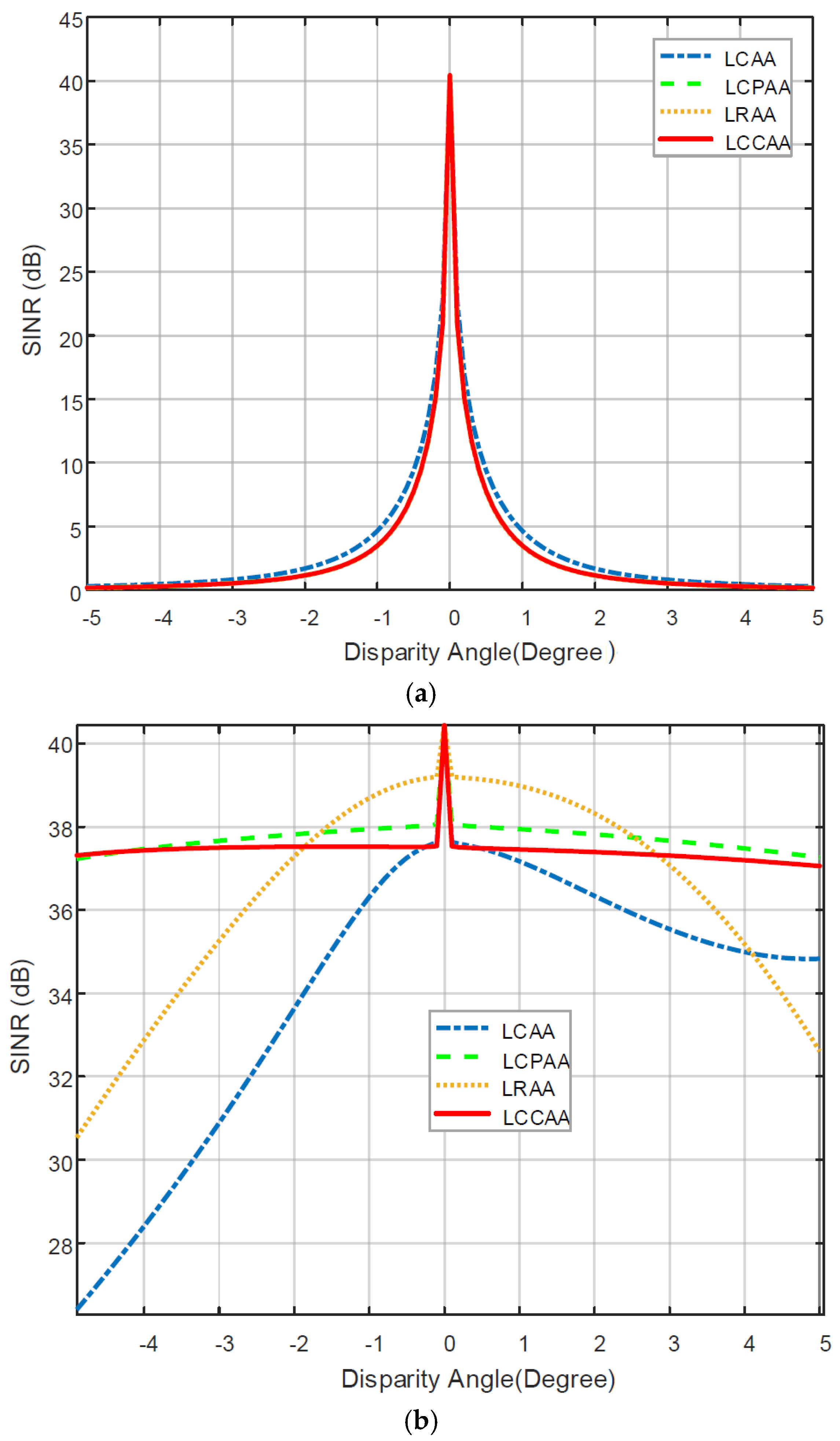
4.2.1. SINR Comparison of the FDL-Based Beamformer with Respect to the Disparity Angle

Figure 3a provides an illustration of this. With 1°, 2°, and 3° disparity, the SINR of the LCAA beamformer is 4.65 dB, 1.69 dB, and 0.52 dB, respectively. The SINR of the LCPAA beamformer is 3.42 dB, 1.15 dB, and 0.53 dB for a 1°, 2°, and 3°differences, respectively. The SINR LRAA beamformer is 3.44 dB, 1.13 dB, and 0.53 dB for a 1°, 2°, and 3° difference, respectively. With 1°, 2°, and 3° difference, the SINR LCCAA beamformer is 3.49 dB, 1.15 dB, and 0.53 dB, respectively. All beamformers with no disparity have an SINR of 40.45 dB. According to the discussion above, the LCCAA beamformer has a greater SINR performance.

4.2.2. SINR Comparison of the ODL-Based Beamformer with Respect to the Disparity Angle

In Figure 3b, the SINR of the LCAA beamformer with 1°, 2°, and 3° disparity is 36.31 dB, 33.13 dB, and 30.39 dB, respectively. With 1°, 2°, and 3° disparity, the SINR of the LCPAA beamformer is 37.94 dB, 37.82 dB, and 37.66 dB, respectively. The SINR LRAA beamformer with 1°, 2°, and 3° disparity is 38.69 dB, 37.29 dB, and 35.26 dB, respectively. The SINR of the LCCAA beamformer is 37.52 dB, 37.52 dB, and 37.49 dB for 1°, 2°, and 3° disparity, respectively. The SINR of all beamformers without disparity is 40.45 dB.

4.2.3. SINR Comparison of the VDL-Based Beamformer with Respect to the Disparity Angle

In Figure 3c, the SINR of the LCAA beamformer with 1°, 2°, and 3° disparity is 38.95 dB, 36.09 dB, and 33.35 dB, respectively. The SINR of the LCPAA beamformer is 40.41 dB, 41.29 dB, and 40.09 dB with 1°, 2°, and 3° differences, respectively. With 1°, 2°, and 3° differences, the SINR of the LRAA beamformer is 40.18 dB, 39.43 dB, and 38.33 dB, respectively. The SINR of the LCCAA beamformer with 1°, 2°, and 3° disparity is 40.41 dB, 40.29 dB, and 40.09 dB, respectively. The SINR of all beamformers without disparity is 40.45 dB. From the above discussion, it is concluded that the LCAA beamformer has a better SINR performance.

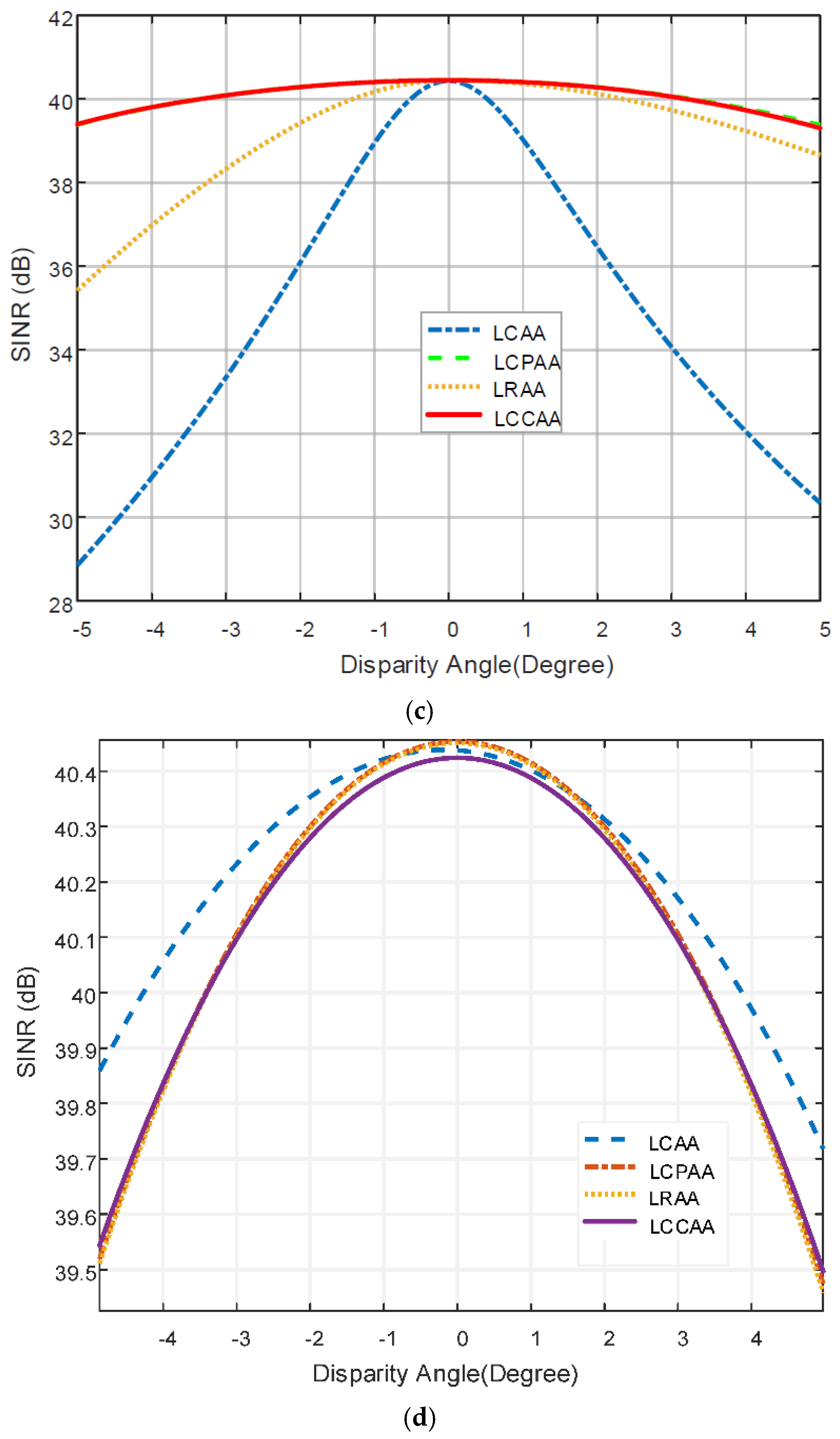
4.2.4. SINR Comparison of the NVL-Based Beamformer with Respect to the Disparity Angle

In Figure 3d, the SINR of the LCAA beamformer with 1°, 2°and 3°disparity is 40.30 dB, 40.23 dB, and 40.11 dB, respectively. With 1°, 2°, and 3°disparity, the SINR of the LCPAA beamformer is 40.29 dB, 40.18 dB, and 39.98 dB, respectively. The SINR of the LRAA beamformer is 40.29 dB, 40.18 dB, and 39.99 dB with 1°, 2°, and 3°disparity, respectively. The SINR of the LCCAA beam former with 1°, 2°, and 3°disparity is 40.29 dB, 40.18 dB, and 39.99 dB, respectively. The SINR of all beamformers without disparity is 40.45 dB. The NVL technique shows a better performance. In Table 1, the value of SINR using robust techniques is shown concerning the corresponding beamformer for different methods.

4.3. Comparison of the Power Patterns for All Beamformers

This section uses FDL, ODL, VDL, and NVL methodologies to compare the output power of LCAA, LCPAA, LRAA, and LCCAA beamformers with respect to the disparity angle (degree). The output power values are also examined for disparities of 1°, 2°, and 3°.

4.3.1. Comparison of the Power Pattern for the FDL-Based Beamformer

In Figure 4a, the output power of the LCCAA beamformer with 1°, 2°, and 3° disparity is −9.78 dB, −7.08 dB, and −18.95 dB, respectively. For 1°, 2°, and 3° disparity, the output power of LCAA is −8.16 dB, −4.69 dB, and −17.07 dB, respectively. Then, the output power of the LCPAA beamformer with 1°, 2°, and 3° disparity is −9.92 dB, −7.33 dB, and −19.10 dB, respectively. The output power of the LRAA beamformer with 1°, 2°, and 3° disparity is −9.83 dB, −7.16 dB, and −18.99 dB, respectively. The output power of LCPAA is higher than that of the other beamformers, as seen in the figure. So, the LCPAA beamformer performed better than the other beamformers.

4.3.2. Comparison of the Power Pattern for the ODL-Based Beamformer

In Figure 4b, the output power of the LCAA beamformer with 1°, 2°, and 3° disparity is −0.289 dB, −0.54 dB and −0.76 dB, respectively. For 1°, 2°, and 3° disparity, the output power of LCPAA is −0.331 dB, −0.623 dB, and −0.885 dB, respectively. Then, the output power of the LRAA beamformer with 1°, 2°, and 3° disparity is −0.21 dB, −0.39 dB, and −0.55 dB respectively. The output power of the LCCAA beamformer with 1°, 2°, and 3° disparity is −0.36 dB, −0.68 dB, and −0.95 dB, respectively. We can deduce from this figure that the output power of LCCAA is higher than that of the other beamformers. In this case, the LCCAA beamformer performance is good.

4.3.3. Comparison of the Power Pattern for the VDL-Based Beamformer

In Figure 4c, the output power of the LCAA beamformer with 1°, 2°, and 3° disparity is −0.01dB, −0.05 dB, and −0.11 dB, respectively. For 1°, 2°, and 3° disparity, the output power of LCPAA is −0.0227dB, −0.084 dB, and −0.185dB, respectively. Then, the output power of the LRAA beamformer with 1°, 2°, and 3° disparity is −0.02 dB, −0.078 dB, and −0.18 dB, respectively. The output power of the LCCAA beamformer with 1°, 2°, and 3° disparity is −0.022 dB, −0.082 dB, and −0.18 dB, respectively. The output power of the LCPAA is higher than that of the other beamformers, as seen in the figure. The LCPAA beamformers performed very well.

4.3.4. Comparison of the Power Pattern for the NVL-Based Beamformer

In Figure 4d, the output power of the LCAA beamformer with 1°, 2°, and 3° disparity is −0.008 dB, −0.04 dB, and −0.10 dB, respectively. For 1°, 2°, and 3° disparity, the output power of LCPAA is −0.01955 dB, −0.078 dB, and −0.178 dB, respectively. Then, the output power of the LRAA beamformer with 1°, 2°, and 3° disparity is −0.018 dB, −0.075 dB, and −0.171 dB, respectively. The output power of the LCCAA beamformer with 1°, 2°, and 3° disparity is −0.019 dB, −0.076 dB, and −0.171 dB, accordingly.
The output power of the LCPAA is higher than that of the other beamformers, as seen in the figure. In the NVL robust technique, the performance of the LCPAA beamformer is better. In Table 1, the SINR of the robust techniques (FDL, ODL, VDL, and NVL) is shown with respect to the disparity angle.
The comparison of the power pattern for all beamformers using robust techniques is shown in Table 2 with respect to the corresponding beamformers for the different methods. The NVL technique outperforms the others. The comparison of the power pattern with the disparity angle for different robust techniques is shown in Table 2. The LCPAA beamformer performs better when using the NVL robust technique.

5. Conclusions

In this paper, the performance analysis of the LCAA, LCPAA, LRAA, and LCCAA beamformers is compared with the ODL, FDL, VDL, and NVL techniques. The proposed robust NVL technique showed a better performance. The conventional technique is applied to LCAA, LCPAA, LRAA, and LCCAA, but it cannot detect the interference and an optimal technique has been applied to peak the actual signal and detect the interference. This proposed beamformer has been further analyzed by applying robust techniques, namely ODL, FDL, and VDL, which reduce the beam width. The LCCAA beamformer outperforms others, with a beam width of 12.55° and a sidelobe level of −15.1 dB in the conventional techniques. With an output power of −85.59 dB, LCCAA surpasses other beamformers with the optimal method. In the robust FDL approach, the LCCAA beamformer has a beam width of 10.3° at an output power −20 dB and a sidelobe level of −1.35 dB, which is better than the other beamformers. In the robust ODL approach, the LCPAA beamformers have a greater beam width performance than the other beamformers. With an output power of −20 dB and a sidelobe level of −15.1 dB, the LCPAA beamformer has a beam width of 12.26°. The LCPAA beamformer leads other beamformers in terms of beam width in the robust VDL method, with a beam width of 12.51° at an output power of −20 dB and sidelobe level of −15.1 dB. In the robust NVL approach, the LCPAA beamformer outperforms the others with a beam width of 12.53° at an output power −20 dB and sidelobe level of −17.1 dB. Moreover, the NVL technique provides the least beam width of 33.11°. The NVL approach SINR outperforms the others, with 1°, 2°, and 3° disparities, the SINR of the LCAA beamformer is 40.30 dB, 40.23 dB, and 40.11 dB; the SINR of the LCPAA beam-former is 40.29 dB, 40.18 dB, and 39.98 dB; the SINR of the LRAA beamformer is 40.29 dB, 40.18 dB, and 39.99 dB; and the SINR of the LCCAA beamformer is 40.29 dB, 40.18 dB, and 39.99 dB, respectively. All of the beamformers with no disparity have an SINR of 40.45 dB. The LCPAA beamformer performs better in the NVL robust approach, with output powers of −0.01955 dB, −0.078 dB, and −0.178 dB, respectively. Finally, analyzing the simulation results, we can conclude that the proposed NVL technique is better than any other technique and provides an optimum performance for reducing the beam width, sidelobe level, and interference cancellation.

Author Contributions

I.R. and M.A.H. presented the idea, performed the experiments, and prepared the manuscript. N.S.S.S. prepared funding acquisition. M.A.B.Z. contributed to the supervision of the research work. A.K.B. contributed to the investigation of the research work. M.A.R. and G.E.M.A. contributed to software development. M.S.J. and N.S. contributed to writing and reviewing. All authors have read and agreed to the published version of the manuscript.

Funding

This research has been sponsored by INTI International University, Malaysia in terms of software simulation and sponsoring this research work from beginning till publication.

Institutional Review Board Statement

Not applicable.

Informed Consent Statement

Not applicable.

Data Availability Statement

Not applicable.

Acknowledgments

The authors wish to extend their sincere thanks to the support of Centre of Graduate Studies, Universiti Teknologi, PETRONAS, Malaysia, and the Faculty of Data Science and Information Technology, INTI International University, Malaysia for providing the state-of-the-art research facilities to carry out this work. In addition to this, the authors are also thankful for the support provided by the collaborators from Condition Monitoring System, National Centre of Robotics and Automation, Mehran University of Engineering and Technology, Jamshoro, Sindh Pakistan. The entire project has been sponsored by the Faculty of Data Science and Information Technology, INTI International University, Malaysia, for the necessary results.

Conflicts of Interest

The authors declare no conflict of interest.

References

  1. Godara, L.C. Smart Antenna; CRC Press: Boca Raton, FL, USA, 2004. [Google Scholar]
  2. Yang, G.; Li, J.; Wei, D.; Xu, R. Study on wide-angle scanning linear phased array antenna. IEEE Trans. Antennas Propag. 2017, 66, 450–455. [Google Scholar] [CrossRef]
  3. Rahaman, I.; Hossain, M.S.; Reza, M.F.; Sarkar, P.K. Performance Analysis of Linearly-arranged Concentric Circular Antenna Array Using Robust ODL technique. In Proceedings of the 2020 IEEE Region 10 Symposium (TENSYMP), Dhaka, Bangladesh, 5 June 2020; pp. 226–229. [Google Scholar]
  4. Mangoud, M.A.; Elragal, H.M.; Alshara, M.T. Design of time modulated concentric circular and concentric hexagonal antenna array using hybrid enhanced particle swarm optimisation and differential evolution algorithm. IET Microw. Antennas Propag. 2014, 8, 657–665. [Google Scholar] [CrossRef] [Green Version]
  5. Ioannides, P.; Balanis, C.A. Uniform circular and rectangular arrays for adaptive beamforming applications. IEEE Antennas Wirel. Propag. Lett. 2005, 4, 351–354. [Google Scholar] [CrossRef]
  6. Dessouky, M.I.; Sharshar, H.A.; Albagory, Y.A. Efficient sidelobe reduction technique for small-sized concentric circular arrays. Prog. Electromagn. Res. 2006, 65, 187–200. [Google Scholar] [CrossRef] [Green Version]
  7. Avishek, D.; Mandal, D.; Kar, R. Optimal radiation pattern synthesis of mutually coupled antenna array using an efficient compensation method. IET Microw. Antennas Propag. 2021, 15, 1054–1062. [Google Scholar]
  8. Xie, L.; He, Z.; Tong, J.; Li, J.; Li, H. Transmitter polarization optimization for space-time adaptive processing with diversely polarized antenna array. Signal Process. 2020, 169, 107401. [Google Scholar] [CrossRef]
  9. Amirsoleimani, S.; Olfat, A. Single stage DOA-frequency representation of the array data with source reconstruction capability. Signal Process. 2019, 162, 242–252. [Google Scholar] [CrossRef] [Green Version]
  10. Massa, A.; Donelli, M.; Viani, F.; Rocca, P. An innovative multiresolution approach for DOA estimation based on a support vector classification. IEEE Trans. Antennas Propag. 2009, 57, 2279–2292. [Google Scholar]
  11. Marinho, M.A.; Antreich, F.; Caizzone, S.; da Costa, J.P.C.; Vinel, A.; de Freitas, E.P. Robust nonlinear array interpolation for direction of arrival estimation of highly correlated signals. Signal Process. 2018, 144, 19–28. [Google Scholar] [CrossRef]
  12. Ibrahim, M.; Ramireddy, V.; Lavrenko, A.; König, J.; Römer, F.; Landmann, M.; Grossmann, M.; del Galdo, G.; Thomä, R.S. Design and analysis of compressive antenna arrays for direction of arrival estimation. Signal Process. 2017, 138, 35–47. [Google Scholar] [CrossRef] [Green Version]
  13. Kulaib, A.R.; Shubair, R.M.; Al-Qutayri, M.; Ng, J. Accurate and robust DOA estimation using uniform circular displaced antenna array. In Proceedings of the 2015 IEEE International Symposium on Antennas and Propagation & USNC/URSI National Radio Science Meeting, Vancouver, BC, Canada, 19–24 July 2015; pp. 1552–1553. [Google Scholar]
  14. Gan, L.; Yi, Z. Automatic computation of diagonal loading factor for robust adaptive beamforming based on Gaussian distribution. AEU Int. J. Electron. Commun. 2013, 67, 570–573. [Google Scholar] [CrossRef]
  15. Rahaman, I.; Hossain, M.S.; Reza, M.F.; Sarkar, P.K. Linearly-arranged Concentric Circular Antenna Array Beamformer Using Tapering Technique. In Proceedings of the 2019 5th International Conference on Advances in Electrical Engineering (ICAEE), Dhaka, Bangladesh, 26–28 September 2019; pp. 648–652. [Google Scholar]
  16. Rahaman, I.; Hossain, M.S.; Reza, M.F.; Ullah, S.M.N.; Rashid, M.M. Linearly-arranged Concentric Circular Antenna Array Using Robust VDL technique. In Proceedings of the 2019 4th International Conference on Electrical Information and Communication Technology (EICT), Khulna, Bangladesh, 20–22 December 2019; pp. 1–5. [Google Scholar]
  17. Reza, M.F.; Hossain, M.S. Robust concentric circular antenna array with variable loading technique in the presence of look direction disparity. Prog. Electromagn. Res. 2017, 57, 35–43. [Google Scholar] [CrossRef]
  18. Gurkaynak, I.A.; Al-Mashhadani, M.K.S.; Ali, M.H.; Al-Mashhadani, T.F.; Gunduz, A.E.; Yucel, M.; Goktas, H.H. Widely Flatness Gain Bandwidth with Double Pass Parallel Hybrid Fiber amplifier. Opt. Quantum Electron. 2021, 53, 359. [Google Scholar] [CrossRef]
Figure 1. (a) Linear circular antenna array (LCAA); (b) linear rectangular antenna array (LRAA); (c) linear circular planer antenna array (LCPAA); (d) linearly arranged concentric circular antenna array (LCCA).
Applsci 12 11481 g001aApplsci 12 11481 g001b
Figure 2. (a) Performance analysis of all beamformer applying optimal technique. (b) Output power of all beamformer applying optimal technique.
Applsci 12 11481 g002
Figure 3. (a) SINR comparison of FDL-based beamformer with respect to the disparity angle. (b) SINR comparison of ODL-based beamformer with respect to the disparity angle. (c) SINR comparison of VDL-based beamformer with respect to the disparity angle. (d) SINR comparison of the NVL-based beamformer with respect to the disparity angle.
Applsci 12 11481 g003aApplsci 12 11481 g003b
Figure 4. (a) Power pattern comparison of all structures based on the FDL technique with respect to the disparity angle. (b) Power pattern comparison of all structures based on the ODL technique with respect to the disparity angle. (c) Power pattern comparison of all structures based on the VDL technique with respect to the disparity angle. (d) Power pattern comparison of all of the structures based on the NVL technique with respect to the disparity angle.
Applsci 12 11481 g004aApplsci 12 11481 g004b
Table 1. SINR comparison using robust techniques with disparity.
TypesLCAALCPAALRAALCCAA
Robust Techniques
FDL40.454.651.690.5240.453.421.150.5340.453.441.130.5240.453.491.150.53
ODL40.4536.3133.1330.3940.4537.9437.8237.6640.4538.6937.2935.2640.4537.5237.5237.49
VDL40.4538.9536.0933.3540.4540.4141.2940.0940.4540.1839.4338.3340.4540.4140.2940.09
NVL40.4540.3040.2340.1140.4340.2940.1839.9840.4540.2940.1839.9940.4540.2940.1839.99
Table 2. Comparison of the power patterns for all beamformers.
TypesLCAALCPAALRAALCCAA
Robust Techniques
FDL0−8.16−4.69−17.070−9.92−7.33−19.100−9.83−7.16−18.990−9.78−7.08−18.95
ODL0−0.289−0.54−0.760−0.331−0.623−0.8850−0.21−0.39−0.550−0.36−0.68−0.95
VDL0−0.01−0.05−0.050−0.0227−0.084−0.1850−0.02−0.078−0.180−0.022−0.082−0.18
NVL0−0.008−0.04−0.100−0.01955−0.078−0.1780−0.018−0.075−0.1710−0.019−0.076−0.171
Publisher’s Note: MDPI stays neutral with regard to jurisdictional claims in published maps and institutional affiliations.

