Abstract
This paper demonstrates the fabrication of radiation-resistant fiber Bragg grating (FBG) sensors using infrared femtosecond laser irradiation. FBG sensors were written inside acrylate-coated fluorine-doped single-mode specialty optical fibers. We detected the Bragg resonance at 1542 nm. By controlling the irradiation conditions, we improved the signal strength coming out from the FBG sensors. A significant reduction in the Bragg wavelength shift was detected in the fabricated FBG sensors for a radiation dose up to 105 gray, indicating excellent radiation resistance capabilities. We also characterized the temperature sensitivity of the radiation-resistant FBG sensors and detected outstanding performance.
1. Introduction
A fiber Bragg grating is a kind of distributed Bragg reflector, typically a few millimeters in length, which is fabricated inside the fiber core to reflect light at the Bragg wavelength and transmit all other wavelengths. Since their discovery by K. O. Hill et al., fiber Bragg gratings (FBGs) have been considered a promising tool in diverse fields of science and technology [1]. Because of their high-quality optical signal, stability, low cost, and ease of fabrication, FBGs have become an indispensable component in optical sensors, optical networks, wavelength division multiplexing (WDM) systems, photonic signal processing, and industrial applications [2,3,4,5,6]. Depending on the application area, six different structures of FBGs have been reported so far: uniform, Gaussian apodized, raised-cosine apodized, chirped, discrete phase shift, and superstructure [7]. Among the various application areas, the most remarkable is sensing. During the last four decades, a broad range of FBG sensors have been proposed by researchers: strain sensors [8,9,10]; chemical sensors [11,12]; bending sensors [13,14]; medical sensors [15,16]; and temperature sensors [17,18,19]. The application of FBG sensors in the medical sector shows much promise. Julien Bonefacino et al. proposed an ultra-fast polymer optical fiber Bragg grating-based sensor for monitoring the human heartbeat and respiratory functions [15]. Rui Min et al. proposed a polymer optical fiber-based FBG sensor for monitoring human physiological and body functions such as respiration rate, heart rate, foot pressure, and joint movement [16].
In addition to their other sensing applications, FBG sensors have remarkable applications in space science and the power industry, especially the atomic energy industry. However, the quality of most of these FBG sensors degrades with time due to exposure to high amounts of radiation [20,21]. S. Ju reported the temperature and gamma-ray (γ-ray) dependency of optical attenuation in FBG-inscribed silica glass fibers [20]. The attenuation caused by γ-ray irradiation and the temperature variation were measured as 0.185 dB/m and 27.5 × 10⁻⁴ dB/°C, respectively. A. F. Fernandez and his research group detected a 0.25 dB reduction in optical power from FBG temperature sensors due to the long-term radiation effect [21]. As a result, there is huge demand for radiation-resistant sensors. To overcome the impact of radiation on FBG sensors present in the atomic energy industry and space science, researchers have proposed different techniques for fabricating radiation-resistant FBG sensors [22,23]. A. Pal et al. proposed a radiation-resistant FBG sensor system where the FBG sensors written into a photosensitive fiber were connected to a specially designed radiation-resistant optical fiber and shielded by stainless steel tubing. Still, the FBG sensors showed a radiation-induced absorption (RIA) of ~2.2 dB/km [22]. M. A. S. Zaghloul et al. proposed radiation-resistant FBG sensors in random air-line fibers for temperature sensing in nuclear reactor cores. Although the authors claimed that they had developed radiation-resistant FBG sensors, a reduction in the peak signal strength of ~5 dB was detected in the FBG sensors due to long-term exposure to heavy radiation. In addition, a wavelength shift of ~5.5 nm was observed in FBG sensors under long-term radiation [23]. As a result, the development of a stable radiation-resistant FBG sensor remains a challenge to researchers.
Femtosecond lasers have been considered a versatile tool for fabricating micro/nano-structures on the surface of and inside transparent materials [24,25,26,27,28]. Because of their focusing capability inside the fiber core, researchers consider femtosecond lasers to be the most promising technology for fabricating FBG sensors. Initially, femtosecond laser sources operating in the ultraviolet (UV) wavelength range were considered for fabricating FBG sensors [29,30,31]. However, most researchers have utilized infrared (IR) femtosecond lasers for fabricating FBGs [32,33,34,35,36]. A large variety of fabrication techniques have been considered for FBG fabrication, including the point-by-point method [29,32], the holographic method [31], the plane-by-plane method [33], and the phase mask method [30,34,35,36]. Because of the low processing time and high precision, the phase mask method is the most widely used technique for fabricating FBG sensors. A. Martinez et al. demonstrated a UV femtosecond laser-assisted point-by-point inscription technique for the fabrication of FBG sensors used to monitor temperatures in the range between 500 °C and 1050 °C [29]. Another research group proposed for the first time the fabrication of Bragg gratings inside a photonic crystal fiber by a UV femtosecond laser using the phase mask technique for channel dropping, tunable filtering, and channel monitoring [30]. Bragg gratings were fabricated inside a germanosilicate optical fiber core by means of two UV femtosecond laser-assisted holographic technologies [31]. K. K. C. Lee et al. reported the fabrication of a temperature-compensated FBG-based 3D shape sensor by means of a femtosecond laser-assisted point-by-point method [32]. The proposed sensor was designed for bend sensing up to a curvature of 2.5 × 10⁻² mm−1, temperature sensing up to 250 °C, and real-time 3D fiber shape sensing. A novel technique, namely, an IR femtosecond laser-assisted plane-by-plane method, was proposed by K. Bronnikov and his research group where the researchers were successful in measuring the bending sensitivity of fibers ranging between 0.046 nm/m−1 and 0.049 nm/m−1 with an error rate down to ~1% [33]. S. J. Mihailov et al. reported the formation of Bragg gratings inside an all-SiO2 and Ge-doped fiber core by irradiating an IR femtosecond laser on top of a phase mask [34]. The fabricated gratings exhibited low polarization dependence and stable operation at temperatures up to 950 °C. Using the IR femtosecond laser-aided phase mask technique, FBGs were fabricated inside non-photosensitive fibers to achieve a transmission of –25 dB at the Bragg wavelength [35]. Most of these research works were limited to the characterization of the FBG sensors in terms of reflected power, RIA, and sensitivity and the demonstration of the fabrication technique. None of the reported research works examined the impact of laser parameters on the performance of the FBG sensors. In addition, the benefit of using an IR laser over an UV laser in respect of the performance of FBG sensors remains undiscovered. Thus, it is desirable to investigate the impact of laser wavelength and other laser parameters on the performance of the FBG sensors, especially radiation-resistant sensors.
In this paper, we report the fabrication of radiation-resistant FBG sensors using the IR femtosecond laser-assisted phase mask technique. Acrylate-coated fluorine (F)-doped silica fibers were considered for producing radiation-resistant FBG sensors suitable for operating under heavy γ-ray radiation. The Bragg resonance was detected at 1542 nm. We investigated for the first time the influence of various fabrication conditions on the performance of the FBG sensors. To optimize the laser parameters for achieving the highest reflected signal power, we fabricated the FBG sensors by varying various laser parameters including beam diameter, focal length, laser power, and laser exposure time. To optimize the performance of the FBG sensors, we varied the laser power, laser exposure time, and length of the FBG under the optimized fabrication conditions. Furthermore, we compared the performance of the IR femtosecond laser-inscribed FBG sensors with the commercially available UV femtosecond laser beam-fabricated FBG sensors. The IR femtosecond laser-based FBG sensors showed higher reflected power with excellent temperature sensitivity compared with the UV femtosecond laser-based FBG sensors. In addition, we compared the performance of the F-doped silica fiber-based FBG sensors with the Ge-doped silica fiber-based FBG sensors. A significant reduction in the wavelength shift was noticed in the F-doped FBG sensors fabricated using optimized laser parameters. The wavelength shift was constant over a wide range of radiation doses (0–105 gray), indicating outstanding radiation resistance. On the contrary, F-doped FBG sensors showed higher reflected signal power as compared with the Ge-doped FBG sensors. The F-doped FBG sensors show promise as a candidate for a stable radiation-resistant sensor in the atomic energy industry.
2. Fundamental Concepts
When a broadband light source is transmitted through a FBG-inscribed optical fiber, a particular wavelength, known as the Bragg wavelength (λB), of the incident broadband light source obeys the following phase matching condition [1].
where neff represents the effective refractive index of the FBG region of the fiber core and Λ represents the gratings’ period. The Bragg wavelength undergoes strong reflection from the FBG while the remaining spectrum transmits through the FBG. The Bragg wavelength can be shifted by controlling the gratings’ period and/or the effective refractive index of the FBG. Temperature sensitivity is inherent to fiber Bragg gratings where the primary contributor to Bragg wavelength shift is the variation in the neff in the FBG region caused by the mechanical stress (σ) and temperature (T). In addition, thermal expansion alters the gratings’ period, which is less significant due to the low thermal expansion coefficient of silica fiber. A change in the refractive index (Δn) can be estimated by the following Equation [2].
where σref and Tref refer to the reference values of the local stress and temperature, respectively, and Δσ and ΔT represent the incremental deviations in the local stress and temperature from their reference values, respectively. If the change in the Bragg wavelength is denoted by ΔλB, Equation (2) can be elaborated as follows [2]:
where is the strain with the ± sign exemplifying the tensile and compressive stresses. Equation (3) can be rewritten using Young’s modulus (Y) and the thermal expansion coefficient (α) [2,3].
where εz is the axial strain, εr is the radial strain, P11 and and P12 are Pockel’s coefficients, α = 0.55 × 10⁻⁶/°C (for silica fiber) is the thermal expansion coefficient, ζ = 5.77 × 10⁻⁶/°C (for silica fiber) is the thermo-optic effect, and Pe is the photo-elastic coefficient of the fiber (Pe ≈ 0.22 for Ge-doped silica fiber). Thus, from Equation (4), the temperature dependence of FBG sensors, i.e., the Bragg wavelength shift due to a change in the temperature, can be determined by the following equation.
Figure 1a illustrates the basic principle of FBG sensors for measuring temperature sensitivity. We utilized the phase mask technique [30,34,35,36] to fabricate the gratings inside the fused silica glass sample and optical fibers. The +1/−1-order phase mask was optimized to diffract light equally into the +1 and −1 orders where the 0-order beam was highly suppressed. The interference between these two orders of diffracted light formed an interference pattern with half the phase mask period, as illustrated in Figure 1b.
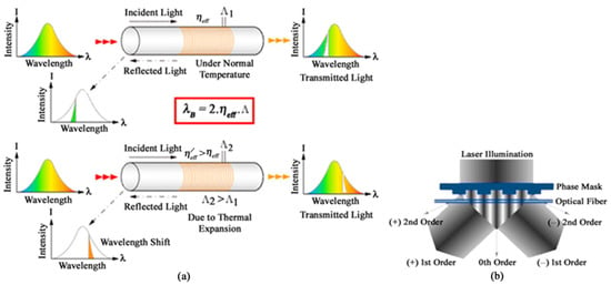
Figure 1.
Basic principles of (a) FBG sensors for the measurement of temperature sensitivity; (b) the laser-assisted phase mask technique for fabricating FBG sensors.
3. Materials and Methods
3.1. Material Properties
During our experiments, we considered acrylate-coated fluorine (F)-doped single-mode specialty optical fibers (core diameter: 8 μm; clad diameter: 125 μm) to fabricate FBGs inside fiber cores. In order to determine the fabrication parameters, we fabricated Bragg gratings inside fused silica glass samples (thickness: 1 mm, refractive index: 1.4533 @ 800 nm) before fabricating the FBG inside the core of the optical fibers.
3.2. Experimental Details
FBGs were inscribed inside the core of the F-doped optical fibers by means of a Ti:Sapphire femtosecond laser (APRI, Femto-K1) operating at the central wavelength (λ) of 800 nm. This laser produced ultra-short laser pulses with a pulse width (τ) of 22 fs at a pulse repetition rate of 1 kHz. The power of the laser pulses coming out from a linearly polarized femtosecond laser system was attenuated by a 360° rotatable quartz phase λ/2 wave plate connected to a polarizing beam splitter transmitting a p-polarized laser beam. Figure 2a represents the image of the femtosecond laser system.
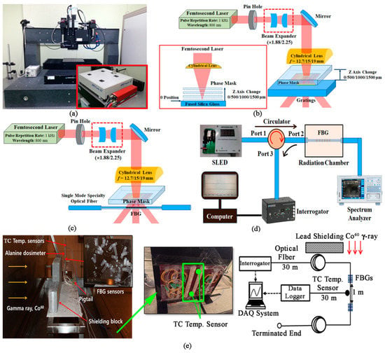
Figure 2.
Experimental setup. (a) Image of the femtosecond laser system; (b) schematic diagram of the fabrication process of Bragg gratings inside fused silica glass; (c) schematic diagram of the fabrication process of FBGs inside the core of optical fibers; (d) measurement technique of the transmitted and reflected signals; (e) measurement technique of the radiation resistance and temperature sensitivity.
The femtosecond laser beam was passed through a pinhole and expanded by a beam expander (Edmund; magnification: ×1.88 and ×2.25), as illustrated in Figure 2b,c. Figure 3 depicts the beam profile of the laser beam, captured by a beam profiler (Thorlabs; BC106N-VIS/M, Newton, NJ, USA), before the beam expander and after different magnifications of the beam expander. Afterwards, the laser beam was passed through one of the three cylindrical lenses having focal lengths of 12.7 mm (Thorlabs; LJ1942L2-B), 15 mm (Thorlabs; LJ1636L2-B), and 19 mm (Thorlabs; LJ1095L1-B). Because of the excellent performance in fabricating Bragg gratings in fused silica glass, we selected the beam expander with a magnification of ×2.25 and the cylindrical lens with a 19 mm focal length to fabricate FBGs in optical fibers (Figure 2c).

Figure 3.
Beam profile of the infrared femtosecond laser beam. (a) Before beam expander; (b) after the ×1.88 beam expander; (c) after the ×2.25 beam expander.
For fabricating FBGs inside the fiber core, the incident laser beam was passed through a +1/−1-order phase mask (Ibsen photonics, Farum, Denmark) having a period of 2132 nm. This beam was centered onto the fiber core and scanned horizontally over the cross-section of the fiber core. For optimization, the distance of the phase mask from the sample surface of the fused silica glass was varied from 0 μm to 1500 μm. Since excellent gratings were detected for a distance of 1000 μm in the fused silica glass, we selected 1000 μm as the distance between the optical fiber surface and the phase mask during the fabrication of the radiation-resistant FBGs sensors. To investigate the influence of the irradiation conditions of the laser beam on the FBG signal strength, we controlled the laser power (measured after the cylindrical lens) from 150 mW to 650 mW. Furthermore, the exposure time of the optical fiber samples under the laser beam was varied between 1 s and 20 s. In contrast, we varied the grating lengths from 3 mm to 18 mm under the optimized laser parameters. We also examined the reproducibility of the proposed technique for fabricating FBG sensors. Moreover, we compared the performance of the femtosecond laser-fabricated FBG sensors with the most widely used commercial ultraviolet (UV) laser-fabricated FBG sensors.
3.3. Measurements and Analysis
To investigate the performance of the FBG sensors, the output from a super-luminescent light-emitting diode (SLED) (Inphenix; IPEVM1020, Livermore, CA, USA) was linked with Port 1 of an optical circulator that passed through Port 2 and reached the FBGs. The signals transmitted through the FBGs were examined using an optical spectrum analyzer (OSA) (Yokogawa; AQ6375, Tokyo, Japan), as illustrated in Figure 2d. In contrast, the reflected signals from the FBGs came from Port 2 to Port 3 and were investigated using an interrogator (Micron Optics; SM125, Atlanta, GA, USA). To study the radiation resistance of the FBG sensors, we placed the FBG sensors inside a Gamma chamber and irradiated them with a Co60 Gamma-ray (γ-ray) at a radiation dose rate of 6000 gray/hour until the accumulated radiation dose reached 105 gray (Gy) (Figure 2e). For radiation resistance measurement, we followed the TIA-455-64 standard. A thermocouple temperature sensor (TC Temp. sensor) was placed adjacent to the FBG sensors to monitor the temperature inside the Gamma chamber. The Bragg wavelength shift and the amplitude of the reflected FBG signal were continuously monitored for a wide temperature range (25 °C to 335 °C).
4. Results and Discussion
4.1. Fabrication of Bragg Gratings inside Fused Silica Glass
To optimize the irradiation conditions of the femtosecond laser beam, we fabricated Bragg gratings 62.5 μm inside (the middle of the gratings) the fused silica glass samples by controlling the beam expansion (BE), the focal length of the cylindrical lens (f), the phase mask’s distance from the glass surface (z), and the laser power (P). The glass samples were exposed under the laser beam for five (05) minutes. When the focal length of the cylindrical lens was 12.7 mm, no Bragg gratings evolved inside the fused silica glass samples, as illustrated in Figure 4a–d, even though we varied the beam expansion and the distance between the phase mask and the glass samples.
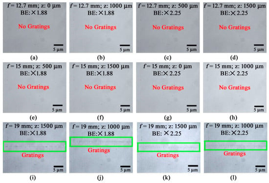
Figure 4.
Formation of Bragg gratings inside fused silica glass for optimization of irradiation conditions of the femtosecond laser beam. (a–d) Using a cylindrical lens with f = 12.7 mm: (a) P: 817 mW, z: 0 μm, BE: ×1.88; (b) P: 817 mW, z: 1000 μm, BE: ×1.88; (c) P: 610 mW, z: 500 μm, BE: ×2.25; (d) P: 610 mW, z: 1500 μm, BE: ×2.25; (e–h) using a cylindrical lens with f = 15 mm: (e) P: 787 mW, z: 500 μm, BE: ×1.88; (f) P: 787 mW, z: 1500 μm, BE: ×1.88; (g) P: 805 mW, z: 0 μm, BE: ×2.25; (h) P: 805 mW, z: 1000 μm, BE: ×2.25; (i–l) using a cylindrical lens with f = 19 mm: (i) P: 787 mW, z: 1500 μm, BE: ×1.88; (j) P: 787 mW, z: 1000 μm, BE: ×1.88; (k) P: 600 mW, z: 1500 μm, BE: ×2.25; (l) P: 600 mW, z: 1000 μm, BE: ×2.25.
Similarly, no Bragg gratings were detected inside the glass samples when the focal length of the cylindrical lens was 15 mm, as depicted in Figure 4e–h. As we know, the Bragg gratings were fabricated by light interference caused by the phase mask. The amount of power in the layer with light interference is expected to be different for different cylindrical lenses having different focal lengths due to the variation in spherical aberrations [37]. The amount of power at the interfering points for the cylindrical lenses having a focal length of 12.7 mm and 15 mm might be lower than the threshold value required to fabricate Bragg gratings inside the fused silica glass sample, which in turn is responsible for the fact that no Bragg gratings were formed inside the fused silica glass sample. We were able to fabricate Bragg gratings inside glass samples only when the distance of the phase mask from the glass sample was 1000 μm or 1500 μm with the cylindrical lens having a focal length of 19 mm (as shown in Figure 4i–l). Although both kinds of beam expander were able to form Bragg gratings, the beam expander having a magnification of ×2.25 consistently showed Bragg gratings in the laser-irradiated area. The best-quality Bragg gratings were observed inside the glass samples when f = 19 mm, BE = ×2.25, and z = 1000 μm (as illustrated in Figure 4l). These parameters can be considered the optimal irradiation conditions of the femtosecond laser beam for fabricating FBGs inside the fiber core.
4.2. Fabrication of Fiber Bragg Gratings
Using the optimal parameters (f = 19 mm, BE = ×2.25, z = 1000 μm), we fabricated 15-mm-long FBGs inside the optical fiber core by means of a femtosecond laser beam with a laser power of 400 mW and an exposure time of 20 s. An image of the FBGs fabricated inside the fiber core is shown at the top of Figure 5a. A magnified image of the FBGs is illustrated at the bottom of Figure 5a. From the interrogator we found that the Bragg wavelength of the fabricated FBGs was 1542 nm. Hence, we obtained a large peak of the reflected signal (15 dB) at the 1542 nm wavelength, as depicted in Figure 5b. We also investigated the transmission spectrum of the incident light that passed through the FBG-engraved optical fiber using an OSA, as represented in Figure 5c. The transmission spectrum also confirmed the absence of the optical signal at the 1542 nm wavelength.
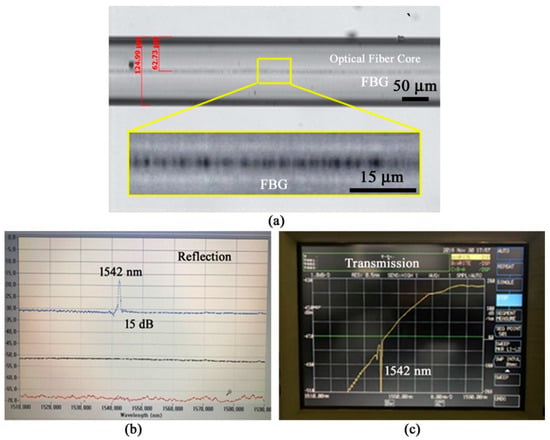
Figure 5.
Characteristics of the FBGs fabricated inside the fiber core. (a) Image of the FBGs; (b) reflected signal from the FBGs at the Bragg wavelength of 1542 nm; (c) transmission spectrum of the FBG-incorporated optical fiber.
4.3. Impact of Fabrication Parameters on the Reflected FBG Signal
We studied the impact of various fabrication parameters on the performance of the FBG sensors. We fabricated 15-mm-long FBGs inside the core of the optical fibers by irradiating the infrared (IR) femtosecond laser beam for 15 s where the laser power, measured immediately after the cylindrical lens, was varied from 150 mW to 650 mW. We measured the strength of the received signal power at the Bragg wavelength of 1542 nm that returned from the FBGs using the interrogator, where the measurement was carried out at room temperature, i.e., 25 °C. Figure 6a–f show images of the received signal power from different FBG sensors fabricated under different laser powers. We detected a substantial difference in the received signal for variation in the irradiation power of the IR femtosecond laser beam.
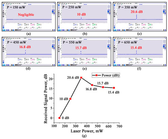
Figure 6.
Interrogator-assisted measurement of the received signal power (at λB = 1542 nm) reflected back from the 15-mm-long FBGs fabricated under different laser powers (P) for an exposure time of 15 s. (a) P = 150 mW; (b) P = 250 mW; (c) P = 350 mW; (d) P = 450 mW; (e) P = 550 mW; (f) P = 650 mW; (g) dependence of the received signal power on the irradiation power of the laser beam.
The received signal power was negligible when the FBGs were fabricated at a laser power of 150 mW, as depicted in Figure 6a. The power of the received signal was 10 dB when the laser power was increased to 250 mW for fabricating FBGs inside the fiber core (Figure 6b). The highest received signal power of 20.6 dB was detected in the FBG sensors fabricated by the femtosecond laser beam at a laser power of 350 mW, as represented in Figure 6c. The received signal power started decreasing again for the FBGs fabricated by a laser power higher than 350 mW, where the received signal power was 16.8 dB for 450 mW, 15.7 dB for 550 mW, and 15.4 dB for 650 mW (Figure 6d–f). The quality and precision of the FBGs are directly dependent on the laser power of the IR femtosecond laser beam. Femtosecond laser irradiation causes a refractive index change in the irradiated area, which is expected to be around 1.9 × 10⁻³ for our sample fiber with the laser parameters used during our experiments [34].
The amount of refractive index change is highly dependent on the laser intensity, where a large refractive index change is observed for a high laser intensity. A change in the refractive index can slightly alter the Bragg wavelength. In addition, the reflectivity of the signal depends on the change in the refractive index and the length of the gratings [36]. At low laser power, the change in the refractive index was low and FBGs might not have formed everywhere inside the fiber core, which caused the received signal power to be low. From the experimental results, we can infer that the best-quality FBGs were formed under the optimal laser power. When the laser power is higher than the optimal value, we expect an increase in the refractive index and heat-affected zone around the gratings, which in turn degrades the quality of the gratings. Hence, the power of the received signal varied with the irradiation power of the femtosecond laser beam and showed the largest peak of 20.6 dB at the optimal laser power of 350 mW. Figure 6g plots the dependence of the received signal power on the irradiation power of the femtosecond laser beam at the Bragg wavelength of 1542 nm.
After we found the optimal laser power (350 mW) of the femtosecond laser beam, we varied the exposure time of the laser beam from 1 s to 20 s for the fabrication of 15-mm-long FBGs inside the fiber core. We measured the signal power at 25 °C. The interrogator outputs of the received signal power reflected from the FBG-inscribed optical fibers, fabricated under different exposure times, are illustrated in Figure 7a–f. The FBGs fabricated using the laser power of 350 mW under a laser exposure of 1 s exhibited a received signal power of 2.9 dB at 1542 nm, as shown in Figure 7a.
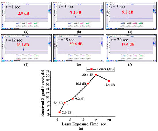
Figure 7.
Interrogator-assisted measurement of the received signal power (at λB = 1542 nm) reflected back from the 15-mm-long FBGs fabricated under different exposure times (t) of the laser beam using a laser power of 350 mW. (a) t = 1 s; (b) t = 3 s; (c) t = 6 s; (d) t = 12 s; (e) t = 15 s; (f) t = 20 s; (g) dependence of the received signal power on the exposure time of the laser beam.
When the exposure time was increased to 3 s, the received signal power was increased to 7.4 dB, as illustrated in Figure 7b. With the increase in the exposure time of the femtosecond laser beam, the power of the received signal increased until the exposure time reached 15 s (Figure 7c–e). The highest signal power of 20.6 dB was detected for an exposure time of 15 s. However, when the exposure time was increased to 18 s, the signal power reduced down to 17.4 dB, as represented in Figure 7f. Thus, we can consider 15 s to be the optimal value of exposure time to fabricate a good-quality FBG sensor. Under a short exposure time, very few laser pulses overlapped in each irradiated spot. Thus, the change in the refractive index along with the width and depth of the grooves inside the gratings were small. Consequently, the reflected signal power was low for short exposure times. Perfect FBGs were fabricated when the exposure time was 15 s. With the increase in the exposure time, the number of laser pulses irradiated in each spot increased, which in turn caused an increase in the refractive index, width, and depth of the gratings. Furthermore, the heat-affected zone around the gratings is expected to increase. As a consequence, the power of the reflected signal was decreased from the highest value for a laser exposure time of 18 s. We fabricated FBGs of different lengths inside the fiber core by means of femtosecond laser beam irradiation with a laser power of 350 mW and an exposure time of 15 s. The interrogator’s output was measured at 25 °C. Figure 8a illustrates that a signal peak of 15.1 dB was detected at 1542 nm when the length of the FBG was only 3 mm.
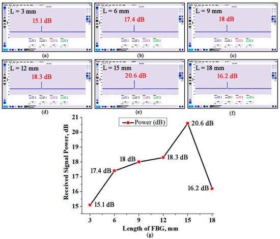
Figure 8.
Interrogator-assisted measurement of the received signal power (at λB = 1542 nm) reflected back from FBGs of different lengths (L) fabricated by irradiating a femtosecond laser beam with a power of 350 mW for 15 s. (a) L = 3 mm; (b) L = 6 mm; (c) L = 9 mm; (d) L = 12 mm; (e) L = 15 mm; (f) L = 18 mm; (g) dependence of the received signal power on the length of the FBGs.
For a FBG with a length of 6 mm, we measured a signal peak of 17.4 dB, as shown in Figure 8b. The received signal power was 18 dB for a FBG with a length of 9 mm, as depicted in Figure 8c. A further increase in the received signal power was achieved by increasing the length of the FBG to 15 mm (Figure 8d,e), where the highest signal power of 20.6 dB was detected from the 15-mm-long FBG. However, when the FBG’s length was 18 mm, the signal power decreased down to 16.2 dB, as shown in Figure 8f. The decrease in the signal power with a FBG length greater than 15 mm might have been due to the high losses introduced by the fiber core and FBGs. As a result, we can consider 15 mm to be the optimal length of the FBG for a good-quality FBG sensor. Figure 8g demonstrates the dependence of the received signal power on the length of the FBG. After accumulating all the experimental results, we obtained the following optimal fabrication parameters: a laser power of 350 mW, an exposure time of 15 s, and a FBG length of 15 mm.
4.4. Reproducibility of the Fiber Bragg Gratings
To examine the reproducibility of the FBGs inside the fiber core, we fabricated FBGs inside ten (10) F-doped silica fibers under same irradiation conditions: a femtosecond laser power of 350 mW, an exposure time of 15 s, and a FBG length of 5 mm. Afterwards, we measured the received signal power using an interrogator at 25 °C. The received signal power from the nine FBG-incorporated F-doped optical fiber samples is illustrated in Figure 9.
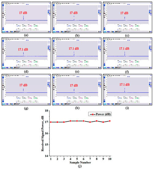
Figure 9.
Received signal power from the FBG-inscribed F-doped optical fiber samples fabricated by IR femtosecond laser irradiated phase mask-assisted fabrication technology with a laser power of 350 mW, an exposure time of 15 s, and a FBG length of 5 mm. (a–i) Received signal power from nine optical fiber samples at the Bragg wavelength of 1542 nm; (j) plot of the received signal power for different optical fiber samples.
A negligible difference in signal strength (~0.1 dB) at 1542 nm was detected from the FBG-incorporated optical fibers. These results indicate excellent reproducibility of FBG sensors using the proposed femtosecond laser irradiated phase mask-assisted fabrication technology.
4.5. Radiation Resistance, Temperature Sensitivity, and Impact of Temperature on the Reflected Signal Power of the FBG Sensors
We examined the radiation resistance of the IR femtosecond (IR FS) laser-fabricated F-doped FBG sensors by placing them inside a Gamma chamber with Co60 γ-rays radiated at 6000 gray/hour, where the accumulated radiation dose was 105 Gy. In addition, we investigated the temperature sensitivity of the F-doped FBG sensors and the power of the reflected signal at the Bragg wavelength under different temperatures. The performance of the IR FS laser-inscribed F-doped FBG sensors were compared with the IR FS and UV femtosecond laser (UV FS)-fabricated Ge-doped FBG sensors. Figure 10 demonstrates the radiation resistance, temperature sensitivity, and impact of temperature on the reflected signal power of the different kinds of F/Ge-doped FBG sensors.
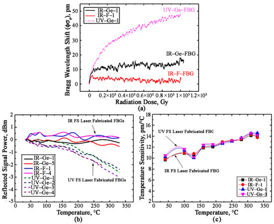
Figure 10.
Radiation resistence, temperature sensitivity, and impact of temperature on the reflected signal power of different kinds of F/Ge-doped FBG sensors fabricated by IR and UV femtosecond lasers. (a) Bragg wavelength shift under Gamma radiation; (b) impact of temperature on the power of the reflected signal at the Bragg wavelength; (c) temperature sensitivity.
It is worth mentioning that Figure 10a confirms a maximum wavelength shift of –5.5 pm under extreme Gamma radiation (05 Gy) in the IR FS laser-fabricated F-doped FBG sensors, which was the lowest among the F/Ge-doped FBG sensors fabricated by IR or UV femtosecond lasers. Under the same amount of radiation, the commercial IR FS laser-inscribed Ge-doped FBG sensor showed a wavelength shift of 11.25 pm. The worst scenario was observed for the commercial UV FS laser-fabricated Ge-doped FBG sensors, where a wavelength shift of ~50 pm was observed under 105 Gy of Gamma radiation. Due to the extreme Gamma radiation inside the Gamma chamber, the temperature of the surrounding environment of the FBG sensors increased significantly, which is a common phenomenon during atomic energy generation. Thus, it is desirable to utilize a stable FBG sensor that exhibits a high reflected signal power at the Bragg wavelength. The UV FS laser-fabricated Ge-doped FBG sensors showed a significant reduction in the reflected signal power (−3 dBm) at the Bragg wavelength of 1542 nm when the surrounding temperature was increased from 25 °C to 335 °C, as evident from Figure 10b. In contrast, the IR FS laser-fabricated FBG sensors showed excellent consistency in the reflected signal power even at high temperatures such as 335 °C where the F-doped FBG sensors showed the best results with a peak reflected signal power of 0.7 dBm. In addition, the reduction in the reflected signal power for the F-doped FBG sensors was just under 0.45 dBm over the temperature range of 25–335 °C. Figure 10c shows the temperature sensitivity of the FBG sensors under a wide range of temperatures varying from 25 °C to 335 °C. Both the IR FS laser and the UV FS laser-inscribed FBG sensors showed excellent temperature sensitivity. For the IR FS laser-fabricated F-doped FBG sensor, the highest temperature sensitivity of 14.4 pm/°C was evident at 310 °C, a value similar to those of the IR FS laser-fabricated Ge-doped FBG sensor and the UV FS laser-inscribed Ge-doped FBG sensors. From the experimental results, we can infer that the wavelength of the femtosecond laser beam has a significant impact on the fabrication of quality FBG sensors. We also compared the performance of the IR FS laser-inscribed FBG sensor with other reported research works, a summary of which is shown in Table 1. Compared with other radiation-resistant FBG sensors, our F-doped FBG sensor shows superior results from all perspectives. Thus, our IR FS laser-fabricated F-doped FBG sensor shows promise as a radiation-resistant sensor, especially in the atomic energy industry.

Table 1.
Comparison of our experimental results with other reported research works.
5. Conclusions
In summary, we fabricated radiation-resistant F-doped FBG sensors for operation under heavy radiation conditions. Infrared femtosecond laser-assisted phase mask technology was used to fabricate the FBGs, having a Bragg resonance at 1542 nm, inside acrylate-coated F-doped silica fibers. Experimental results exemplify that fabrication parameters such as focal length, laser wavelength, laser power, laser exposure time, and grating length have a significant impact on the performance of the FBG sensors. The optimal values of the laser parameters to fabricate high-quality radiation-resistant FBG sensors were: a laser power of 350 mW, a laser exposure time of 15 s, and a FBG length of 15 mm. We compared the performance of our infrared femtosecond laser-fabricated F-doped FBG sensors with commercial Ge-doped FBG sensors fabricated by infrared and ultraviolet femtosecond lasers. The infrared femtosecond laser-fabricated FBG sensors showed better performance as compared with the ultraviolet femtosecond laser-inscribed FBG sensors. Among all FBG sensors, our F-doped sensor showed the best radiation resistance under 105 Gy of Gamma radiation, where the wavelength shift was just −5.5 pm. The highest reflected signal power of 0.7 dBm was detected in the F-doped FBG sensors with a maximum reflected signal power reduction of 0.45 dBm. In contrast, the infrared femtosecond laser-based F-doped FBG sensors showed excellent temperature sensitivity over the temperature range of 25–335 °C, where the highest temperature sensitivity of 14.4 pm/°C was noticed at 310 °C. The temperature sensitivity of the proposed infrared femtosecond laser-fabricated F-doped FBG sensor was the highest among all the studied radiation-resistant FBG sensors. We strongly believe that the proposed radiation-resistant F-doped FBG sensors will play significant role in dynamic application areas, including the atomic energy industry and space research.
Author Contributions
Conceptualization, H.-K.C. and I.-B.S.; methodology, H.-K.C., Y.-J.J., B.-A.Y. and J.-H.S.; validation, I.-B.S., J.-Y.K. and M.S.A.; formal analysis, H.-K.C., B.-A.Y. and J.-H.S.; investigation, H.-K.C., Y.-J.J. and J.-Y.K.; resources, I.-B.S. and J.-Y.K.; writing—original draft preparation, M.S.A.; writing—review and editing, H.-K.C. and I.-B.S.; visualization, H.-K.C. and M.S.A.; supervision, I.-B.S. and J.-Y.K.; project administration, I.-B.S.; funding acquisition, I.-B.S. All authors have read and agreed to the published version of the manuscript.
Funding
This research was funded by a GIST Research Institute (GRI) grant funded by the GIST in 2022, the National Research Foundation of Korea (NRF), Republic of Korea (Research Grant No.: NRF-2017M2A8A4017221), and the High-Efficiency Laser Laboratory of the Agency for Defense Development, Republic of Korea (Research Grant No.: UD190015ID). The APC was funded by the GIST Research Institute (GRI).
Institutional Review Board Statement
Not applicable.
Informed Consent Statement
Not applicable.
Data Availability Statement
Not applicable.
Conflicts of Interest
The authors declare no conflict of interest.
References
- Hill, K.O.; Johnson, D.C.; Kawasaki, B.S. Photosensitivity in optical fiber waveguides: Application to reflection filter fabrication. Appl. Phys. Lett. 1978, 32, 647–649. [Google Scholar] [CrossRef]
- Santos, J.L.; Farahi, F. Handbook of Optical Sensors, 1st ed.; CRC Press: Boca Raton, FL, USA, 2014. [Google Scholar]
- Magne, S.; Rougeault, S.; Vilela, M.; Ferdinand, P. State-of-strain evaluation with fiber Bragg grating rosettes: Application to discrimination between strain and temperature effects in fiber sensors. Appl. Opt. 1997, 36, 9437–9447. [Google Scholar] [CrossRef] [PubMed]
- Senkans, U.; Braunfelds, J.; Lyashuk, I.; Porins, J.; Spolitis, S.; Bobrovs, V. Research on FBG-based sensor networks and their coexistence with fiber optical transmission systems. J. Sens. 2019, 2019, 6459387. [Google Scholar] [CrossRef]
- Zhang, W.; Yao, J. A fully reconfigurable waveguide Bragg grating for programmable photonic signal processing. Nat. Commun. 2018, 9, 1396. [Google Scholar] [CrossRef]
- Allwood, G.; Wild, G.; Hinckley, S. Fiber Bragg grating sensors for mainstream industrial processes. Electronics 2017, 6, 92. [Google Scholar] [CrossRef]
- Erdogan, T. Fiber grating spectra. J. Light. Technol. 1997, 15, 1277–1294. [Google Scholar] [CrossRef]
- Cho, K.; Kim, S.T.; Park, Y.-H.; Cho, J.-R. Measurement of mechanical and thermal strains by optical FBG sensors embedded in CFRP Rod. J. Sens. 2019, 2019, 5345901. [Google Scholar] [CrossRef]
- Liang, M.; Fang, X. Application of fiber Bragg grating sensing technology for bolt force status monitoring in roadways. Appl. Sci. 2018, 8, 107. [Google Scholar] [CrossRef]
- Zhang, R.; Zhu, Z.; Wu, G. Static pure strain sensing using dual-comb spectroscopy with FBG sensors. Opt. Express 2019, 27, 34269–34283. [Google Scholar] [CrossRef]
- Guo, T.; Liu, F.; Guan, B.-O.; Albert, J. Tilted fiber gratings mechanical and biochemical sensors. Opt. Laser Technol. 2016, 78, 19–33. [Google Scholar] [CrossRef]
- Boersma, A.; Cremers, R.; Jansen, R. Fiber Bragg grating distributed chemical sensors. Procedia Eng. 2016, 168, 1245–1248. [Google Scholar] [CrossRef]
- Feng, D.; Zhou, W.; Qiao, X.; Albert, J. Compact optical fiber 3D shape sensor based on a pair of orthogonal tilted fiber Bragg gratings. Sci. Rep. 2015, 5, 17415. [Google Scholar] [CrossRef] [PubMed]
- Chen, X.; Zhang, C.; Webb, D.J.; Kalli, K.; Peng, G.-D. Highly sensitive bend sensor based on Bragg grating in Eccentric core polymer fiber. IEEE Photonics Technol. Lett. 2010, 22, 850–852. [Google Scholar] [CrossRef]
- Bonefacino, J.; Tam, H.-Y.; Glen, T.S.; Cheng, X.; Pun, C.-F.J.; Wang, J.; Lee, P.-H.; Tse, M.-L.V.; Boles, S. Ultra-fast polymer optical fiber Bragg grating inscription for medical devices. Light Sci. Appl. 2018, 7, 17161. [Google Scholar] [CrossRef]
- Min, R.; Hu, X.; Pereira, L.; Soares, M.S.; Silva, L.C.B.; Wang, G.; Martins, L.; Qu, H.; Antunes, P.; Marques, C.; et al. Polymer optical fiber for monitoring human physiological and body function: A comprehensive review on mechanisms, materials, and applications. Opt. Laser Technol. 2022, 147, 107626. [Google Scholar] [CrossRef]
- Laarossi, I.; Roldán-Varona, P.; Quintela-Incera, M.A.; Rodríguez-Cobo, L.; López-Higuera, J.M. Ultrahigh temperature and strain hybrid integrated sensor system based on Raman and femtosecond FBG inscription in a multimode gold-coated fiber. Opt. Express 2019, 27, 37122–37130. [Google Scholar] [CrossRef]
- Pereira, G.; McGugan, M.; Mikkelsen, L.P. Method for independent strain and temperature measurement in polymeric tensile test specimen using embedded FBG sensors. Polym. Test. 2016, 50, 125–134. [Google Scholar] [CrossRef]
- Mohammed, N.A.; Ali, T.A.; Aly, M.H. Performance optimization of apodized FBG-based temperature sensors and quasi-distributed DWDM systems with new and different apodization profiles. AIP Adv. 2013, 3, 122125. [Google Scholar] [CrossRef]
- Ju, S.; Kim, Y.; Linganna, K.; Kim, Y.H.; Han, W.-T. Effect of temperature and Gamma-ray irradiation on optical characteristics of fiber Bragg grating inscribed radiation-resistant optical fiber. Photonic Sens. 2020, 10, 10–33. [Google Scholar] [CrossRef]
- Fernandez, A.F.; Gusarov, A.; Brichard, B.; Decréton, M.; Berghmans, F.; Mégret, P.; Delchambre, A. Long-term radiation effects on fiber Bragg grating temperature sensors in a low flux nuclear reactor. Meas. Sci. Technol. 2004, 15, 1506–1511. [Google Scholar] [CrossRef]
- Pal, A.; Dhar, A.; Ghosh, A.; Sen, R.; Hooda, B.; Rastogi, V.; Ams, M.; Fabian, M.; Sun, T.; Grattan, K.T.V. Sensors for harsh environment: Radiation resistant FBG sensor system. J. Light. Technol. 2017, 35, 3393–3398. [Google Scholar] [CrossRef]
- Zaghloul, M.A.S.; Wang, M.; Huang, S.; Hnatovsky, C.; Grobnic, D.; Mihailov, S.; Li, M.-J.; Carpenter, D.; Hu, L.-W.; Daw, J.; et al. Radiation resistant fiber Bragg grating in random air-line fibers for sensing applications in nuclear reactor cores. Opt. Express 2018, 26, 11775–11786. [Google Scholar] [CrossRef]
- Sohn, I.-B.; Choi, H.-K.; Noh, Y.-C.; Kim, J.; Ahsan, M.S. Laser assisted fabrication of micro-lens array and characterization of their beam shaping property. Appl. Surf. Sci. 2019, 479, 375–385. [Google Scholar] [CrossRef]
- Sohn, I.-B.; Choi, H.-K.; Yoo, D.; Noh, Y.-C.; Noh, J.; Ahsan, M.S. Three-dimensional hologram printing by single beam femtosecond laser direct writing. Appl. Surf. Sci. 2018, 427, 396–400. [Google Scholar] [CrossRef]
- Sohn, I.-B.; Choi, H.-K.; Yoo, D.; Noh, Y.-C.; Sung, J.-H.; Lee, S.-K.; Ahsan, M.S.; Lee, H. Synchronized femtosecond laser pulse switching system based nano-patterning technology. Opt. Mater. 2017, 69, 295–302. [Google Scholar] [CrossRef]
- Choi, H.-K.; Yoo, D.; Sohn, I.-B.; Noh, Y.-C.; Sung, H.-H.; Lee, S.-K.; Jeong, T.-M.; Ahsan, M.S.; Kim, J.-T. CO2 laser assisted fabrication of micro-lensed single-mode optical fiber. J. Opt. Soc. Korea 2015, 19, 327–333. [Google Scholar] [CrossRef][Green Version]
- Sohn, I.-B.; Ahsan, M.S.; Noh, Y.-C.; Choi, H.-K.; Kim, J.-T.; Ko, M.J. Fabrication of Fresnel zone plate lens in fused silica glass using femtosecond laser lithography technology. Opt. Eng. 2014, 53, 055107. [Google Scholar] [CrossRef]
- Martinez, A.; Khrushchev, I.Y.; Bennion, I. Thermal properties of fiber Bragg gratings inscribed point-by-point by infrared femtosecond laser. Electron. Lett. 2005, 41, 176–178. [Google Scholar] [CrossRef]
- Fu, L.B.; Marshall, G.D.; Bolger, J.A.; Steinvurzel, P.; Mägi, E.C.; Withford, M.J.; Eggleton, B.J. Femtosecond laser writing Bragg gratings in pure silica photonic crystal fibers. Electron. Lett. 2005, 41, 638–640. [Google Scholar] [CrossRef]
- Meltz, G.; Morey, W.W.; Glenn, W.H. Formation of Bragg gratings in optical fibers by a transverse holographic method. Opt. Lett. 1989, 14, 823–825. [Google Scholar] [CrossRef] [PubMed]
- Lee, K.K.C.; Mariampillai, A.; Haque, M.; Standish, B.A.; Yang, V.X.D.; Herman, P.R. Temperature-compensated fiber-optic 3D shape sensor based on femtosecond laser direct-written Bragg grating waveguides. Opt. Express 2013, 21, 24076–24086. [Google Scholar] [CrossRef]
- Bronnikov, K.; Wolf, A.; Yakushin, S.; Dostovalov, A.; Egorova, O.; Zhuravlev, S.; Semjonov, S.; Wabnitz, S.; Babin, S. Durable shape sensor based on FBG array inscribed in polymide-coated multicore optical fiber. Opt. Express 2019, 26, 38421–38434. [Google Scholar] [CrossRef] [PubMed]
- Mihailov, S.J.; Smelser, C.W.; Grobnic, D.; Walker, R.B.; Lu, P.; Ding, H.; Unruh, J. Bragg gratings written in all-SiO2 and Ge-doped core fibers with 800-nm femtosecond radiation and a phase mask. J. Light. Technol. 2004, 22, 94–100. [Google Scholar] [CrossRef]
- Thomas, J.; Wikszak, E.; Clausnitzer, T.; Fuchs, U.; Zettner, U.; Nolte, S.; Tünnermann, A. Inscription of fiber Bragg gratings with femtosecond pulses using a phase mask scanning technique. Appl. Phys. A 2007, 86, 153–157. [Google Scholar] [CrossRef]
- Tian, X.; Tao, X. Smart Fibers, Fabrics and Clothing: Fundamentals and Applications, 1st ed.; Woodhead Publishing: Cambridge, UK, 2001. [Google Scholar]
- Suzuki, Y.; Mohri, J.P.; Nakayama, K.; Ando, M.; Sakamoto, K.; Yamauchi, M.; Mizutani, Y.; Yokouchi, T.; Ejima, S. Effect of spherical aberration on fabrication of fiber Bragg gratings. Jpn. J. Appl. Phys. 2006, 45, 5035–5038. [Google Scholar] [CrossRef]
Publisher’s Note: MDPI stays neutral with regard to jurisdictional claims in published maps and institutional affiliations. |
© 2022 by the authors. Licensee MDPI, Basel, Switzerland. This article is an open access article distributed under the terms and conditions of the Creative Commons Attribution (CC BY) license (https://creativecommons.org/licenses/by/4.0/).