
Analysis and Suppression of Self-Excited Oscillations in Pressure Servo Valve System

Abstract
:1. Introduction
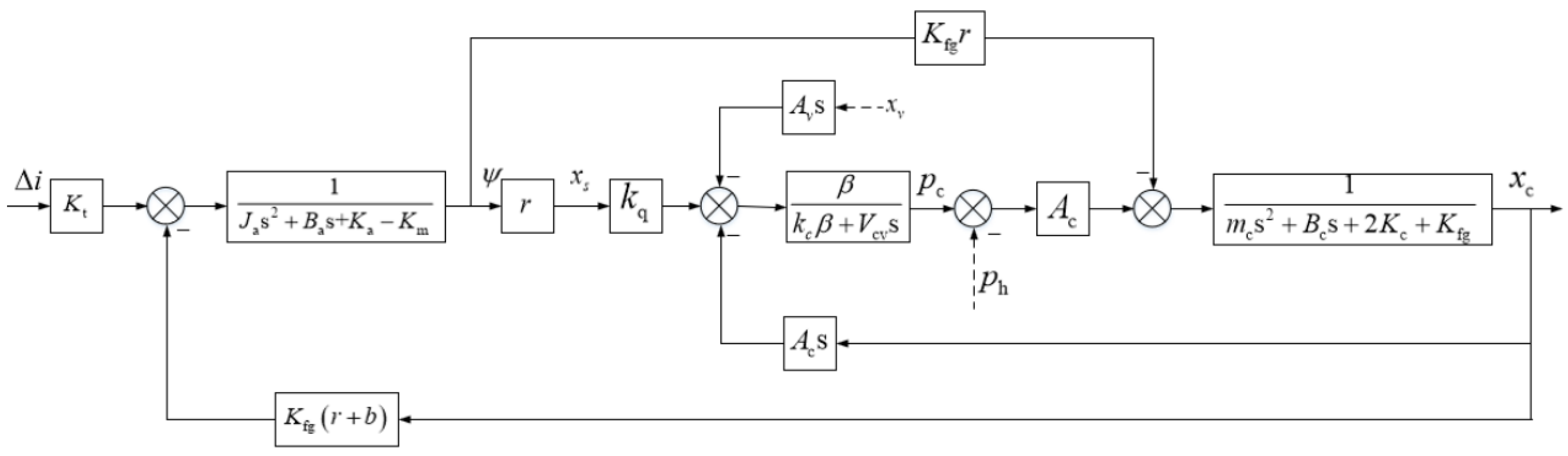
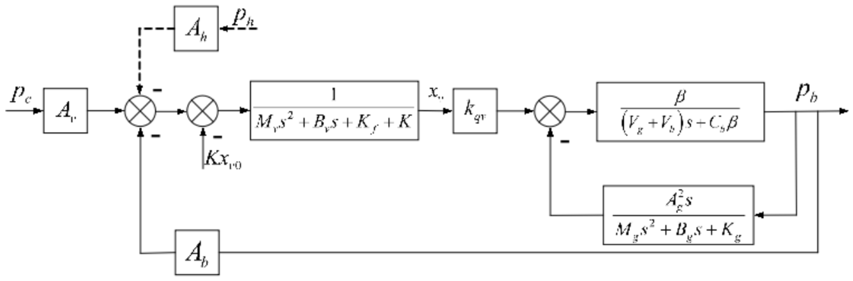
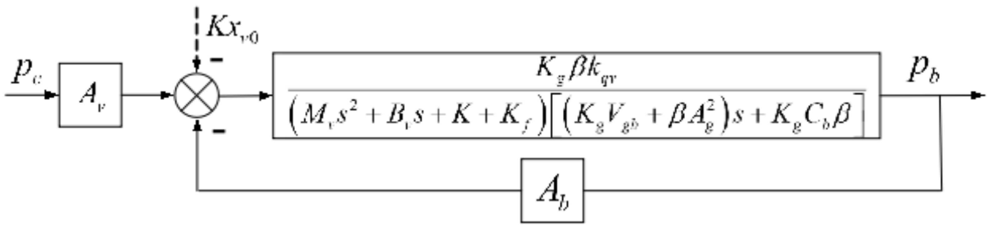
2. Dynamic Model of the PSVS
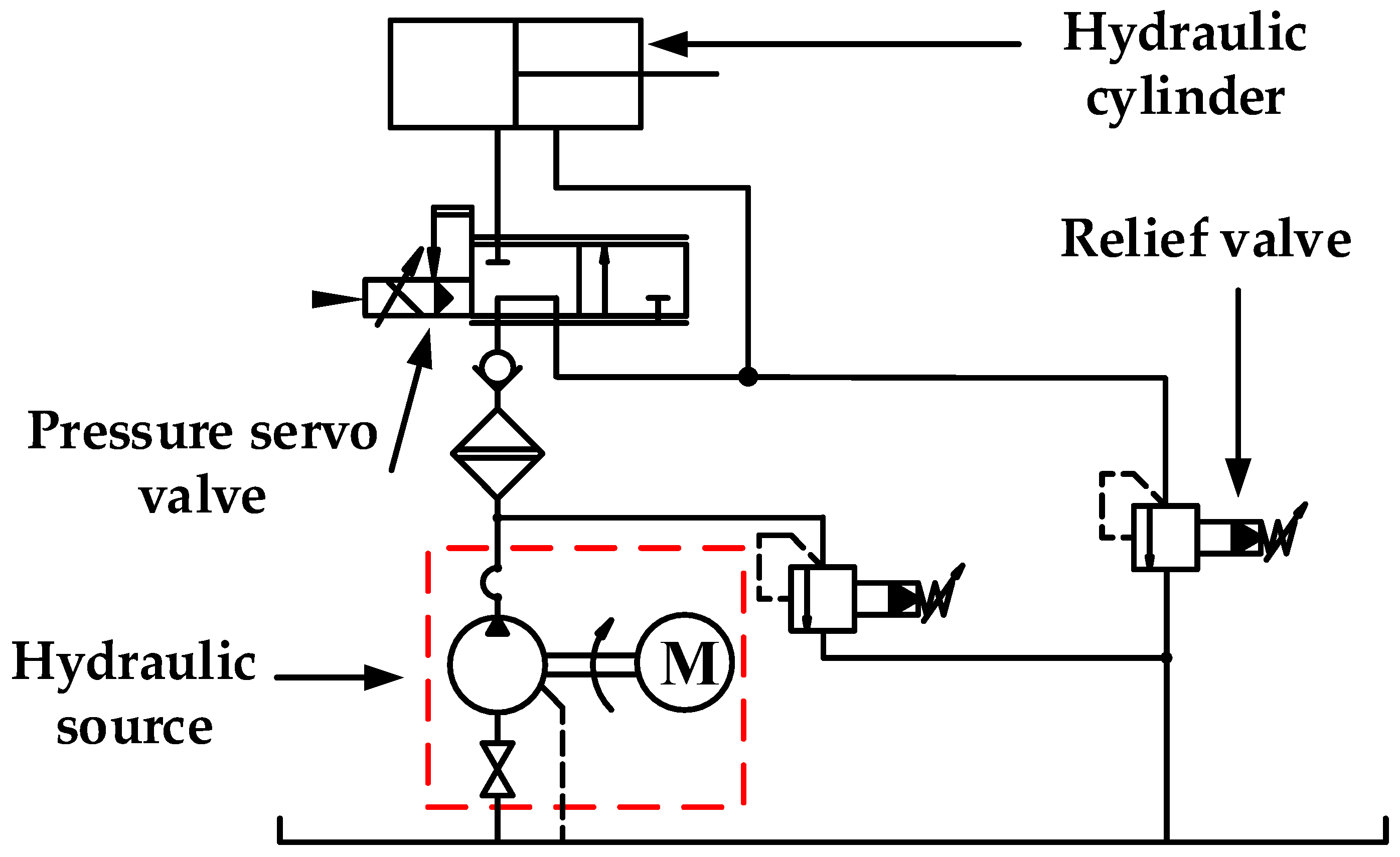
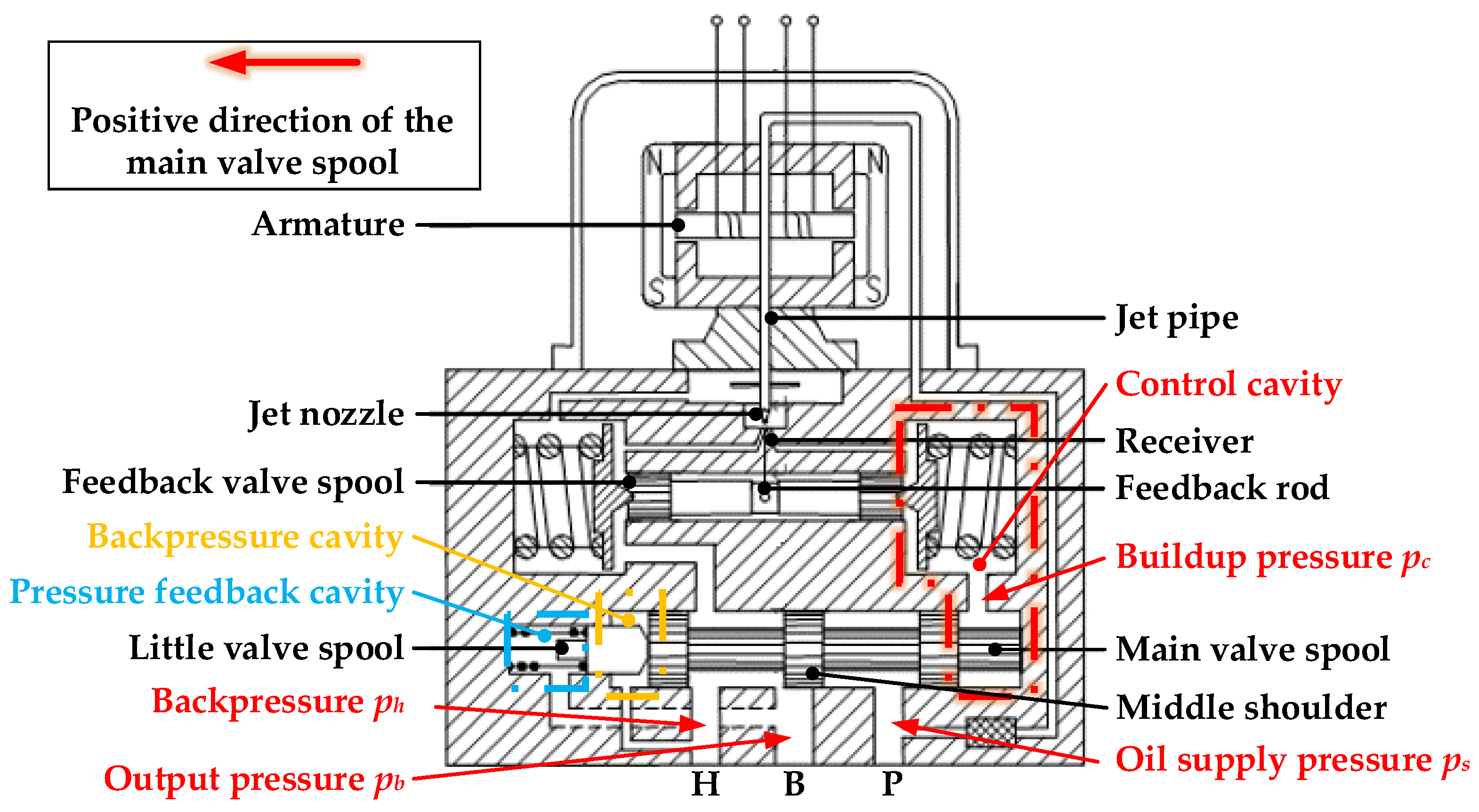
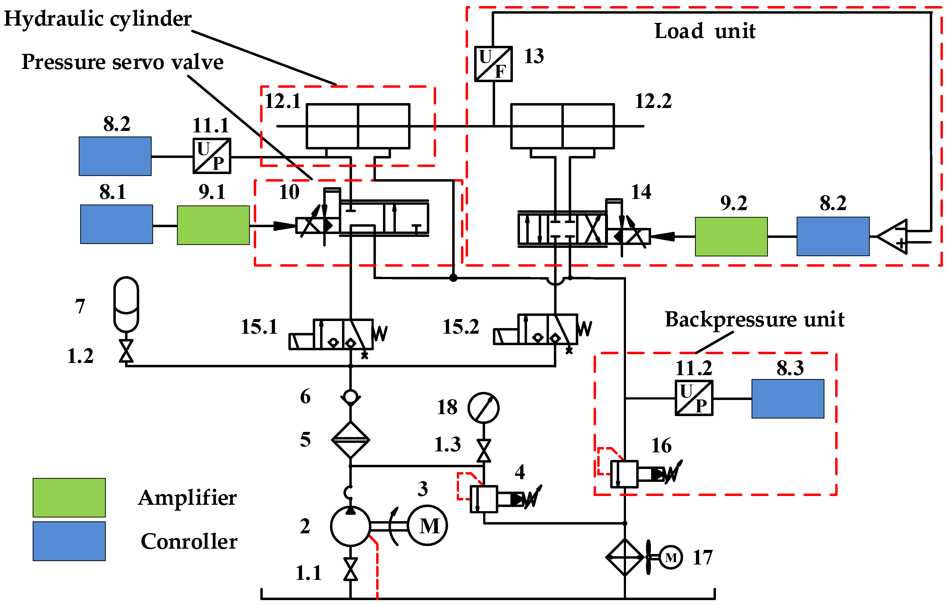
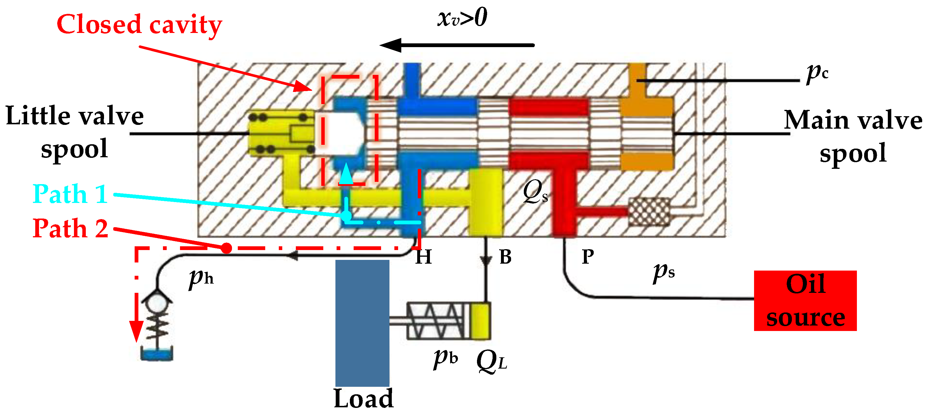
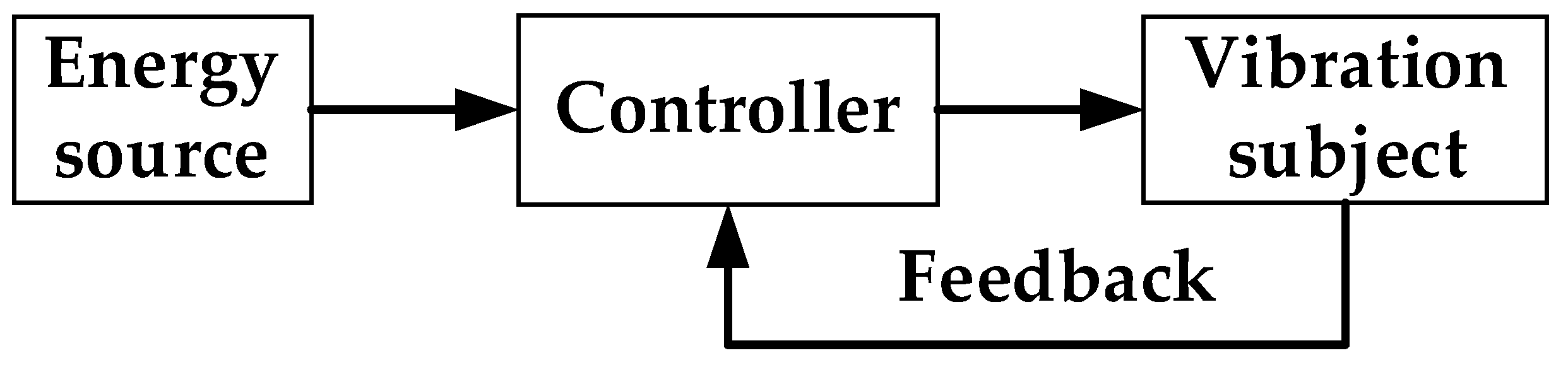
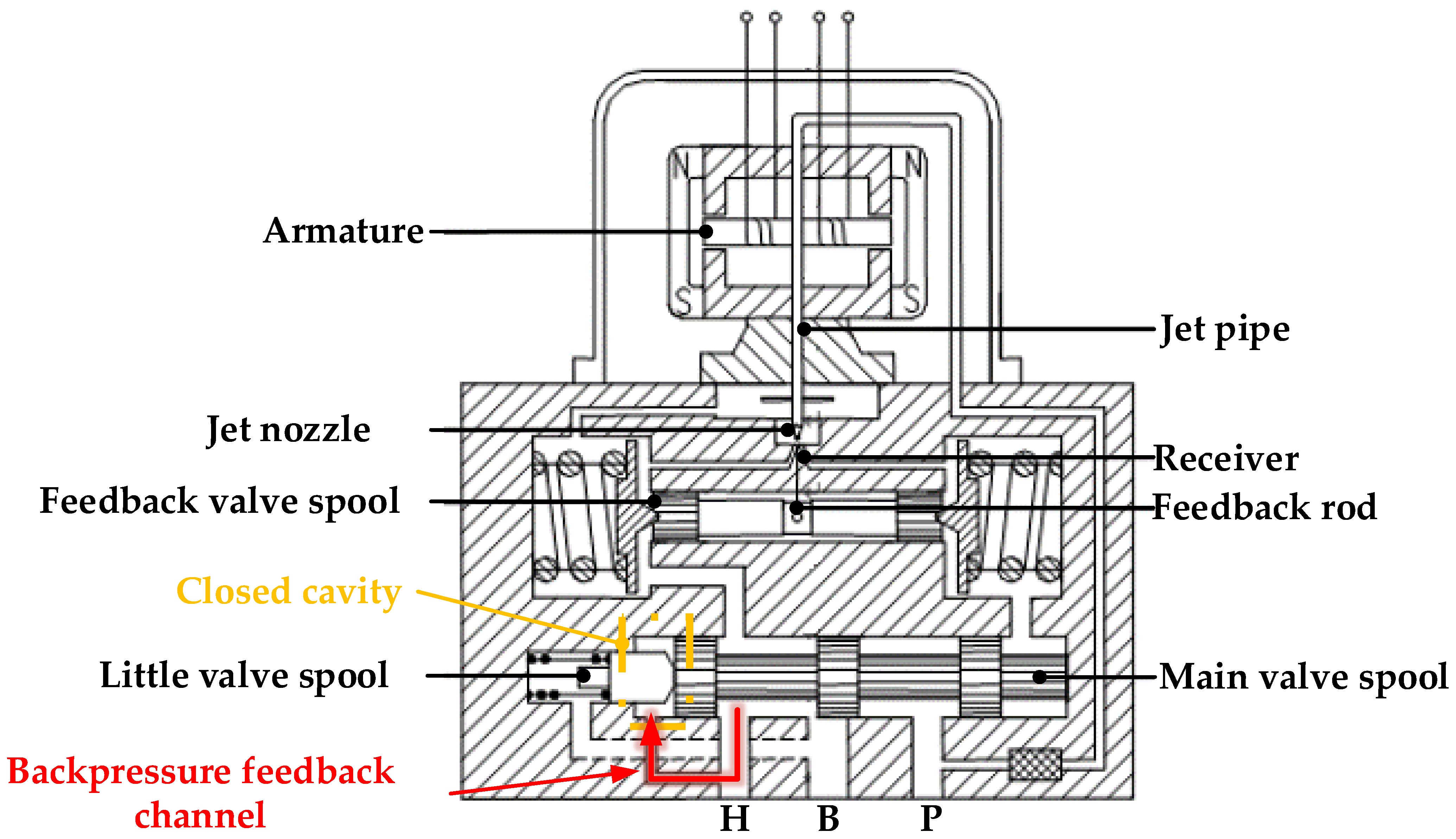
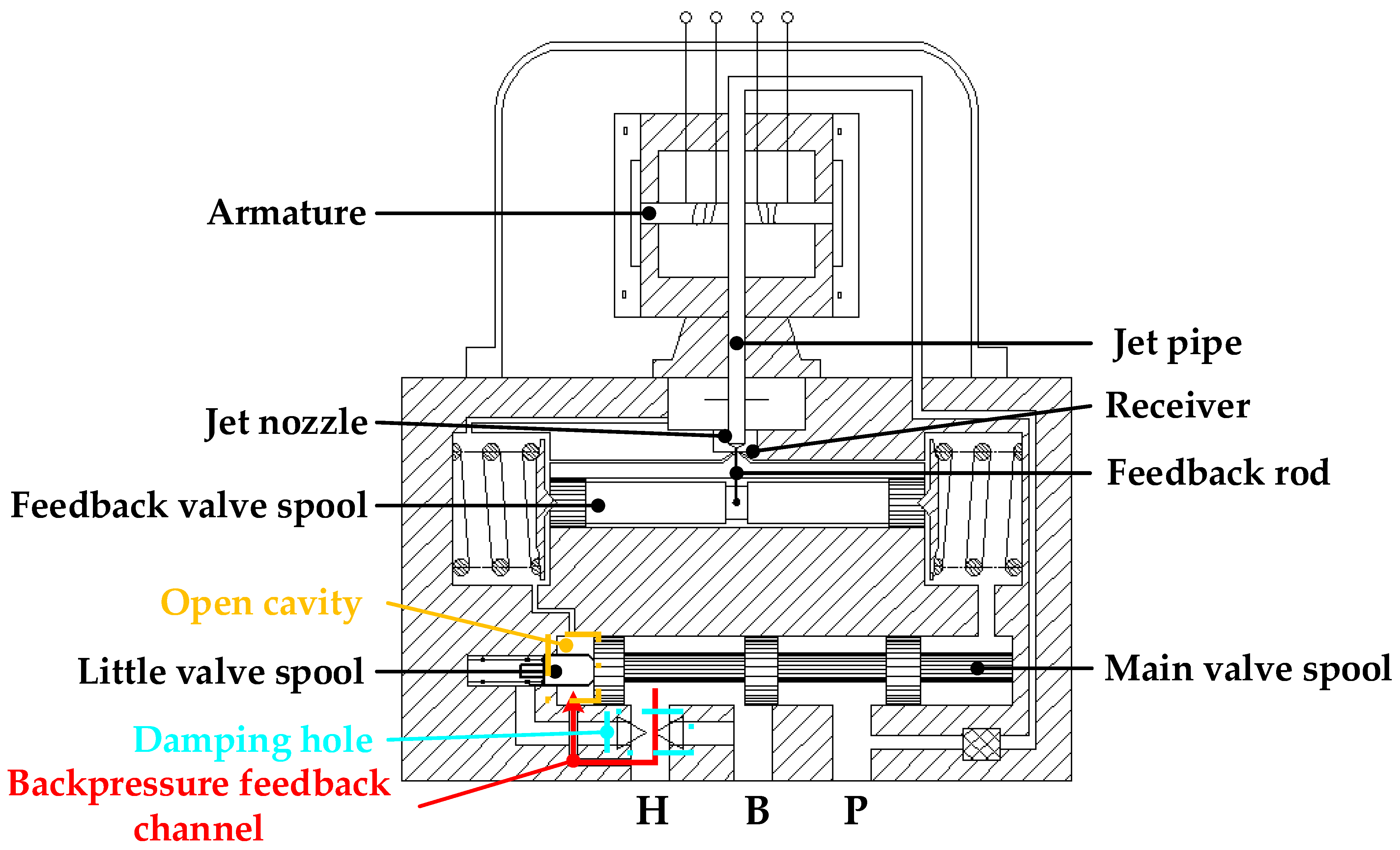
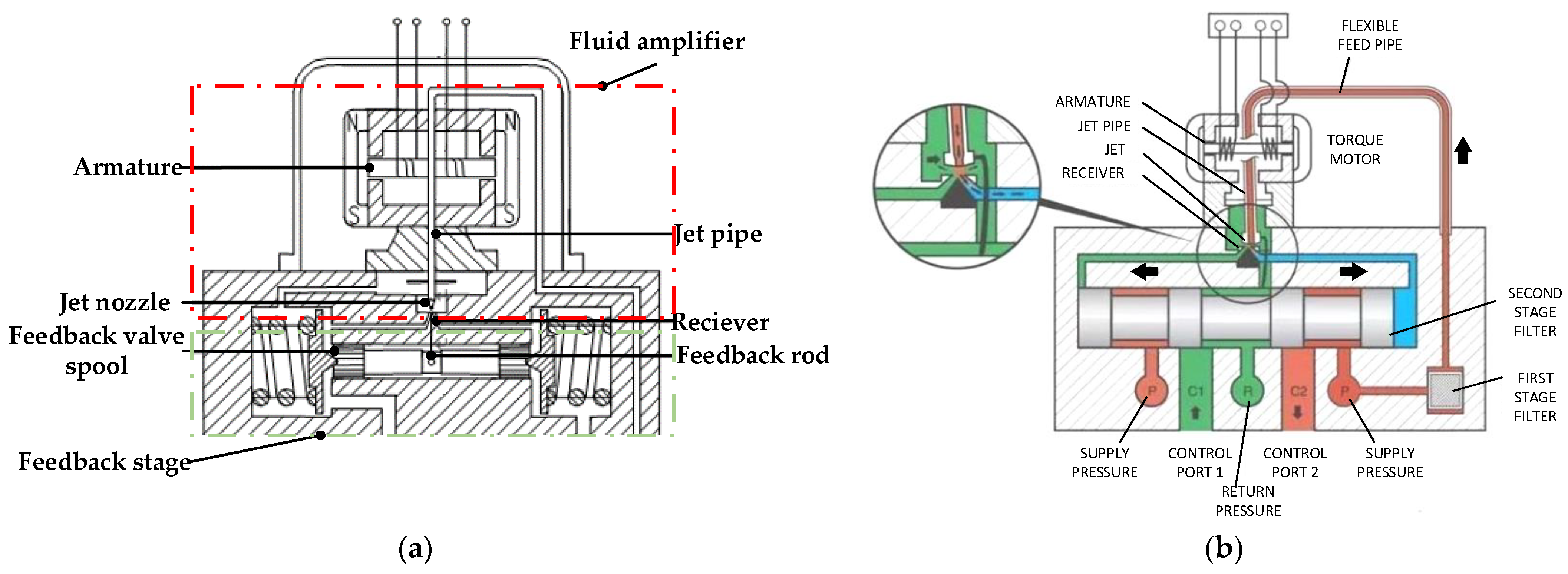
2.1. Working Principle of the System
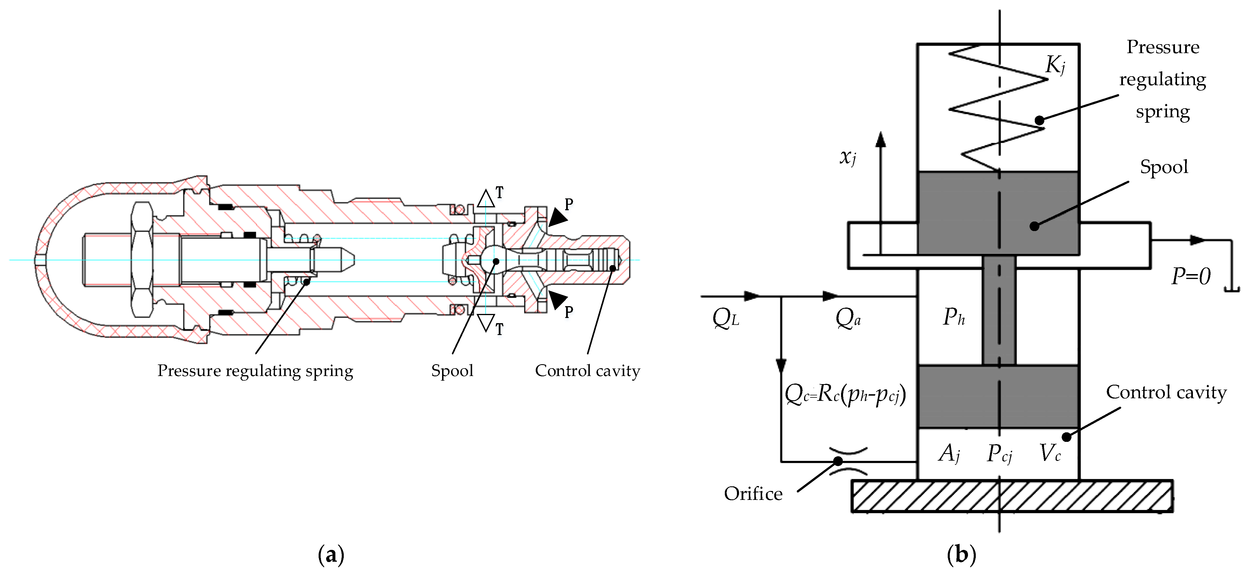
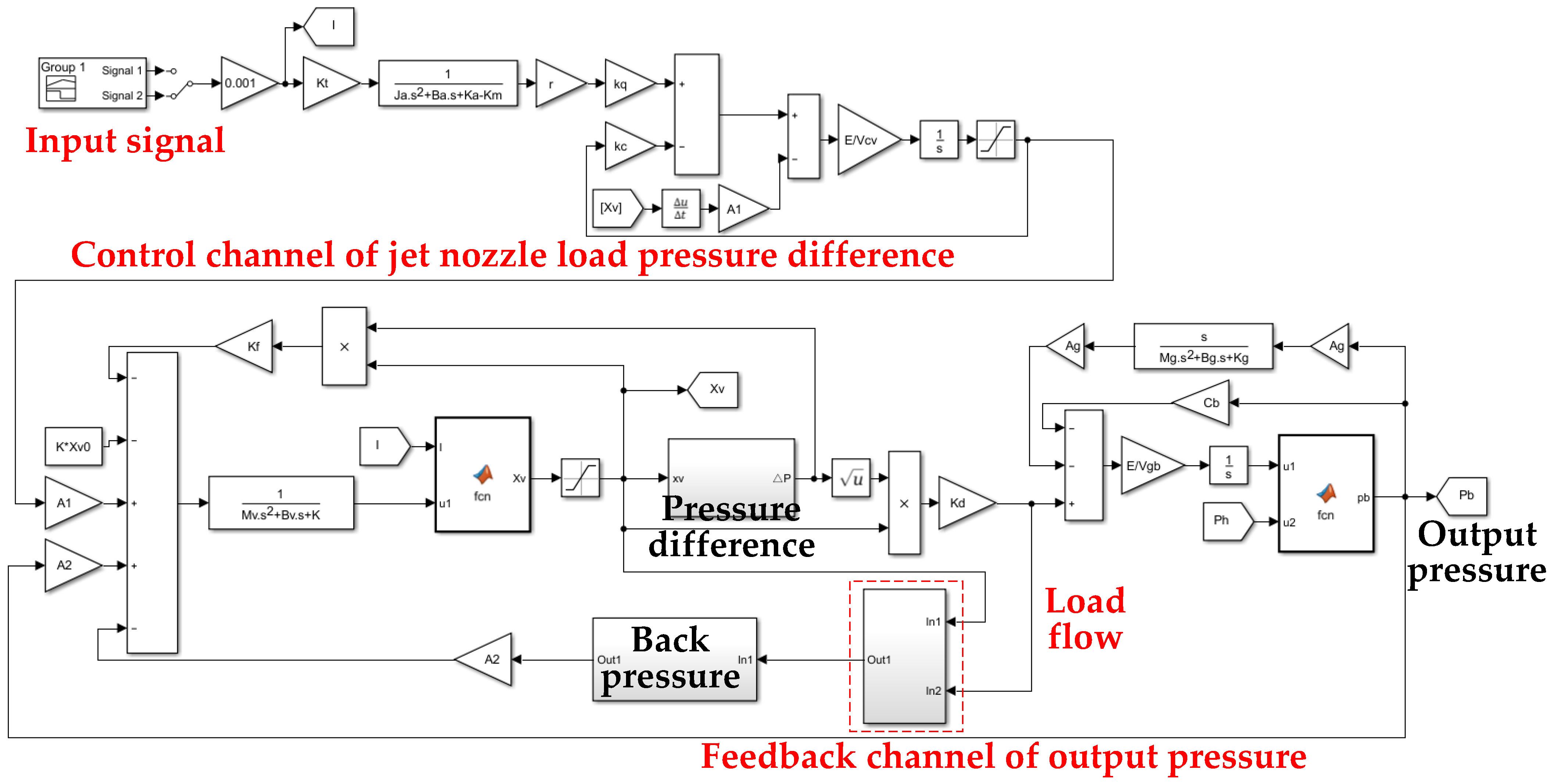
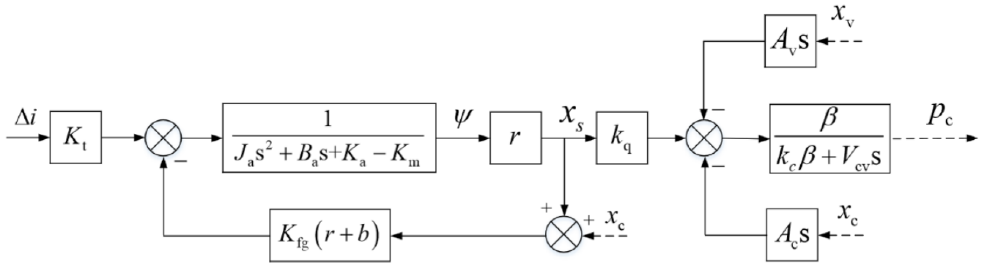
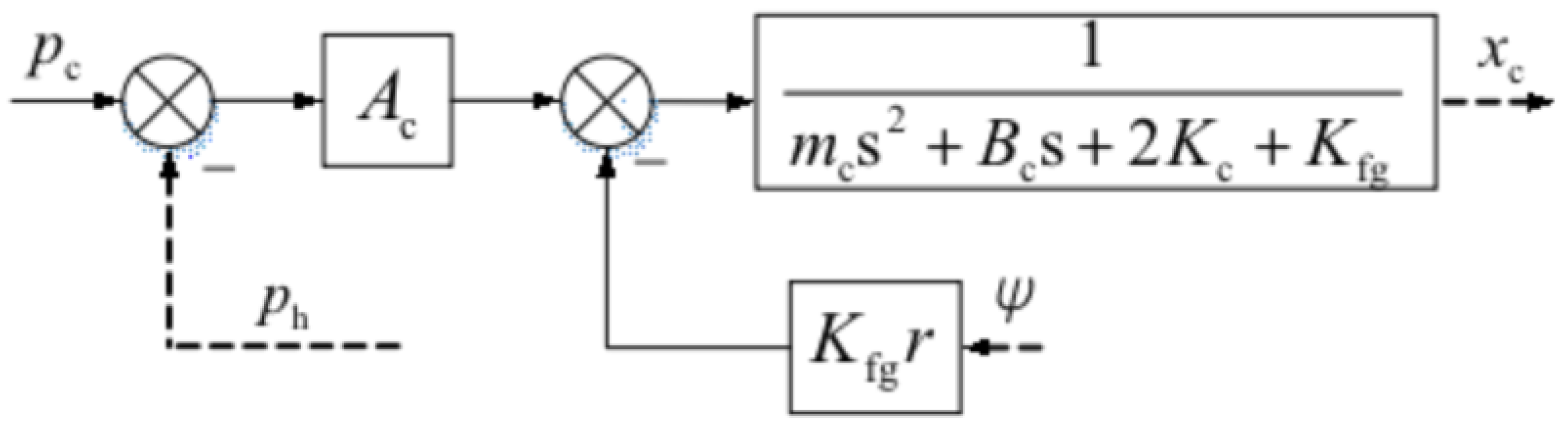
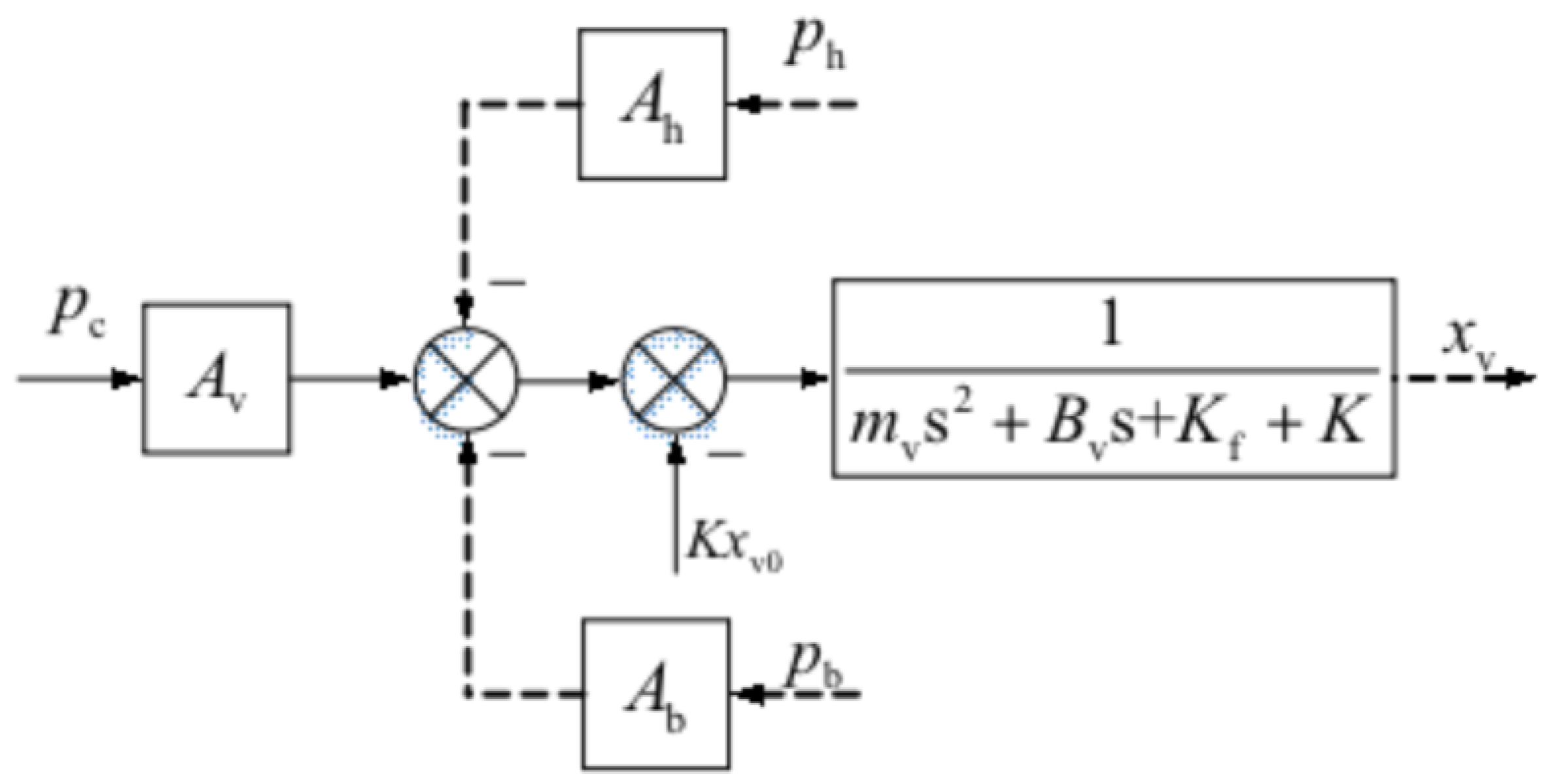
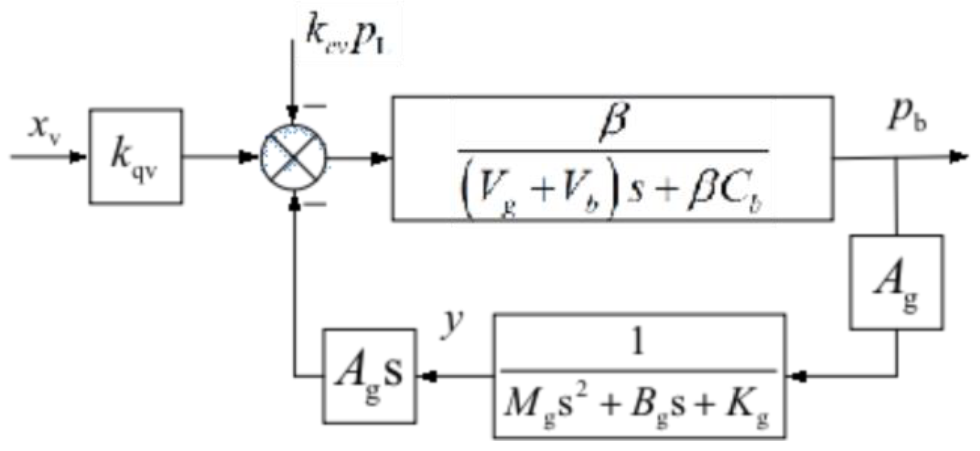
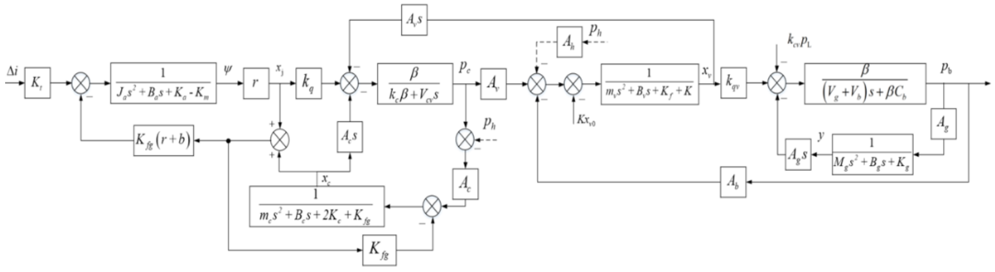
2.2. Dynamic Model of the PSVS
2.3. Simulation Analysis and Experiment
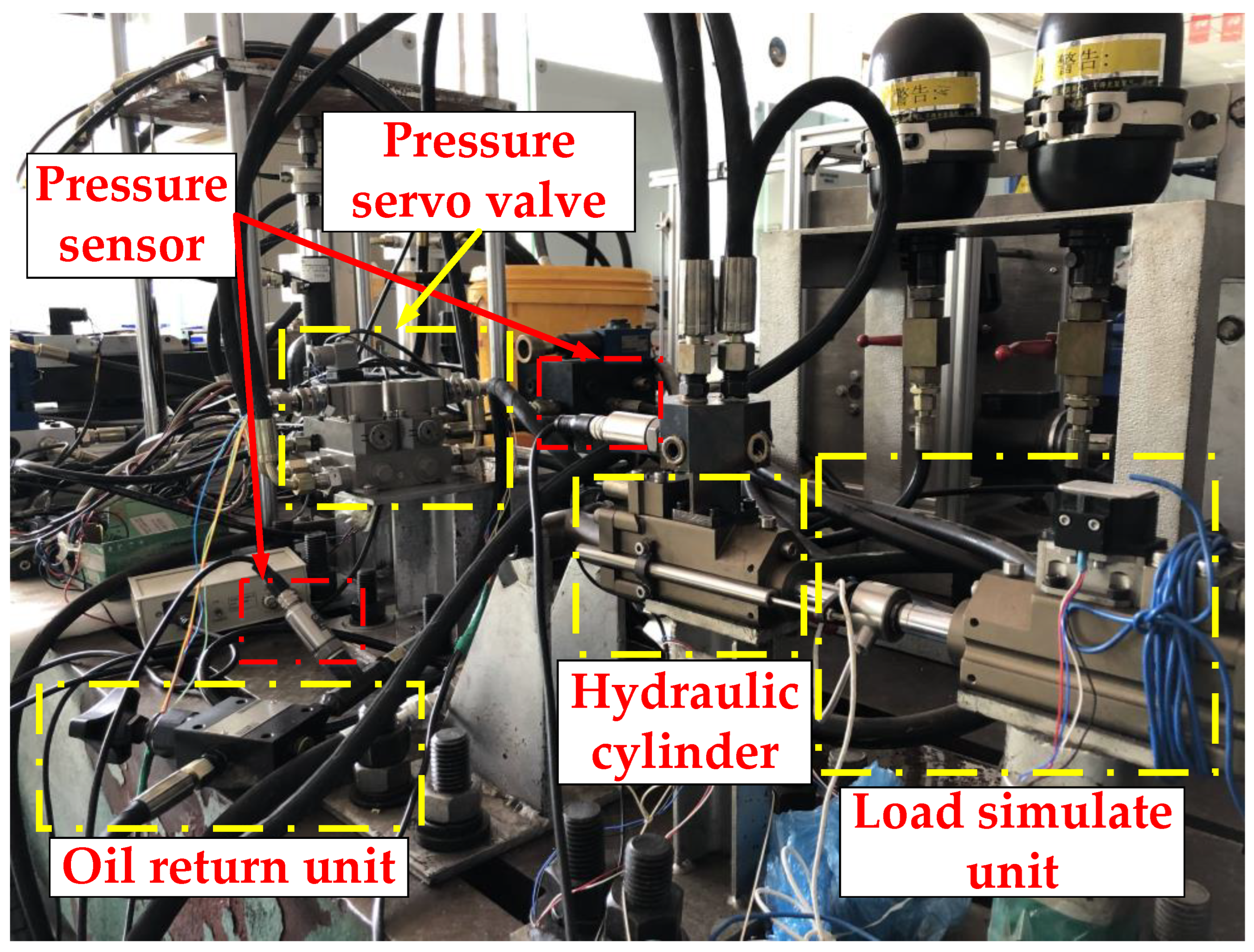
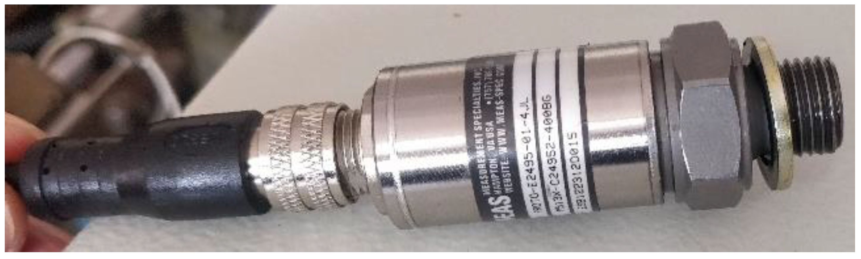
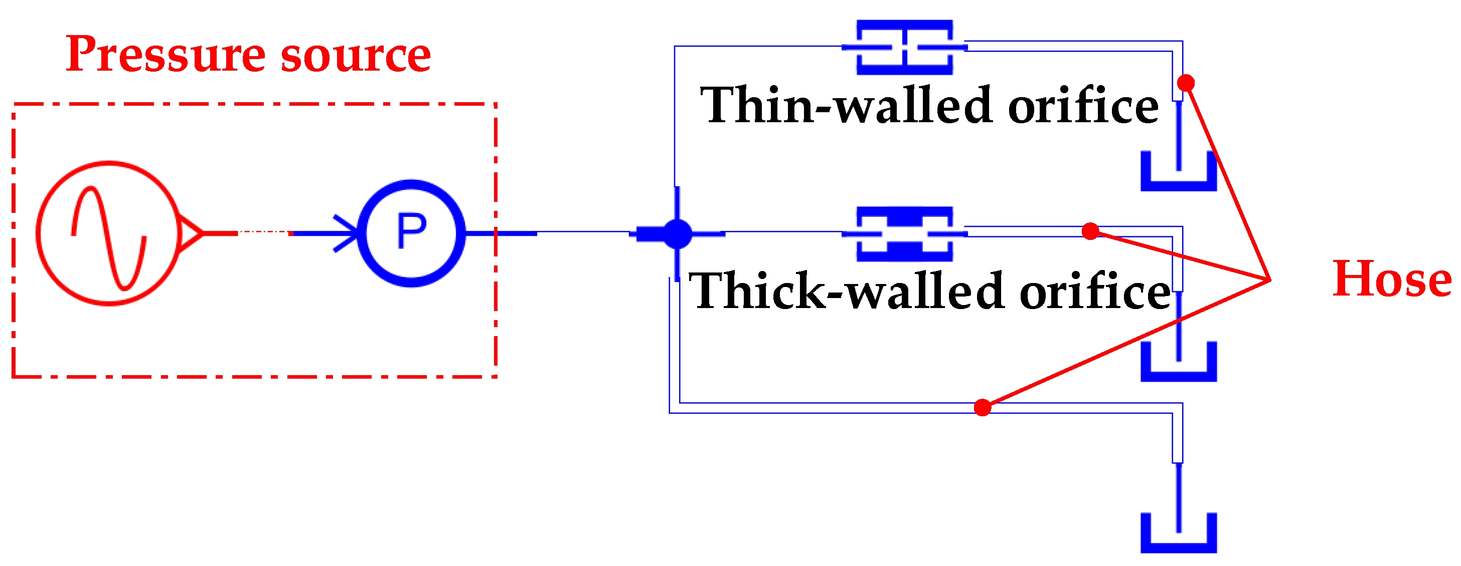
2.3.1. Test Platform
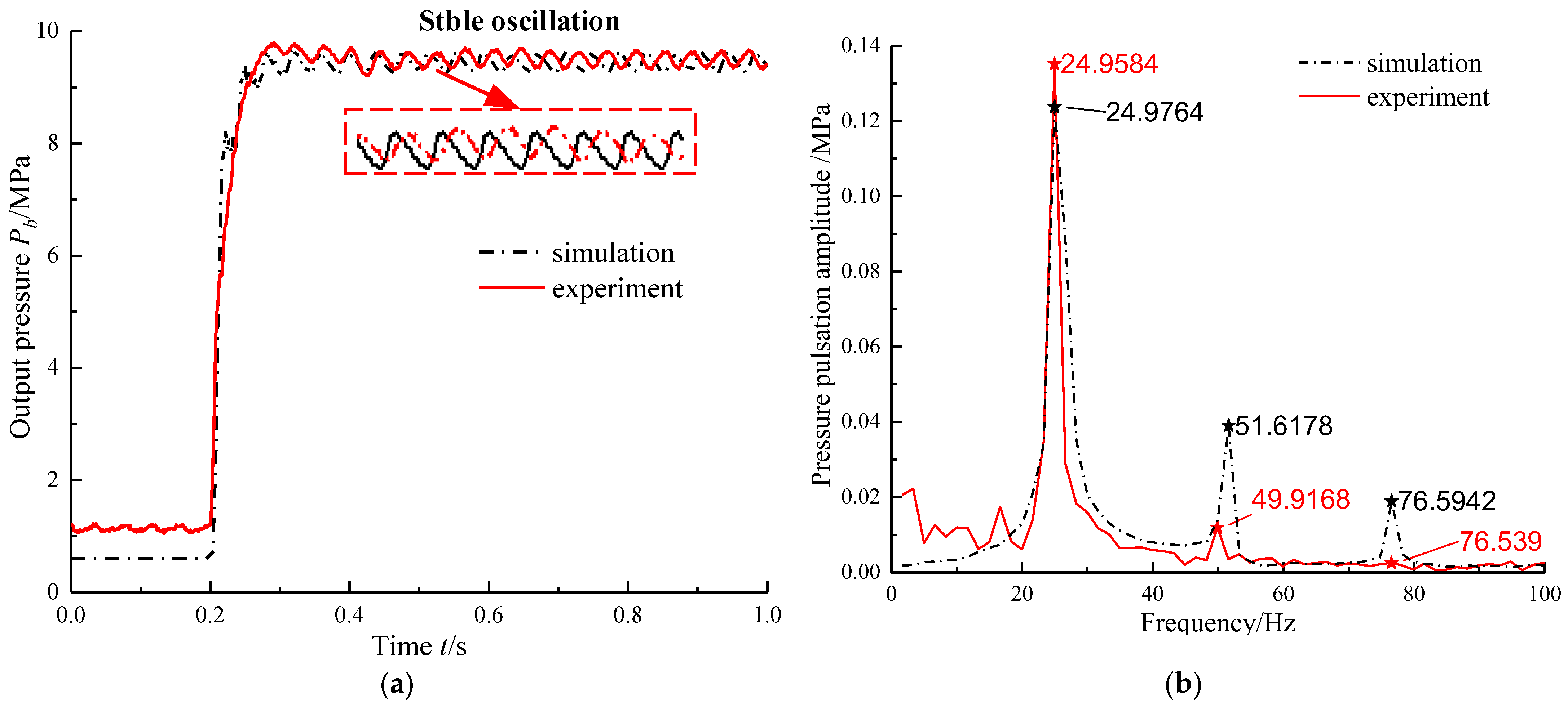
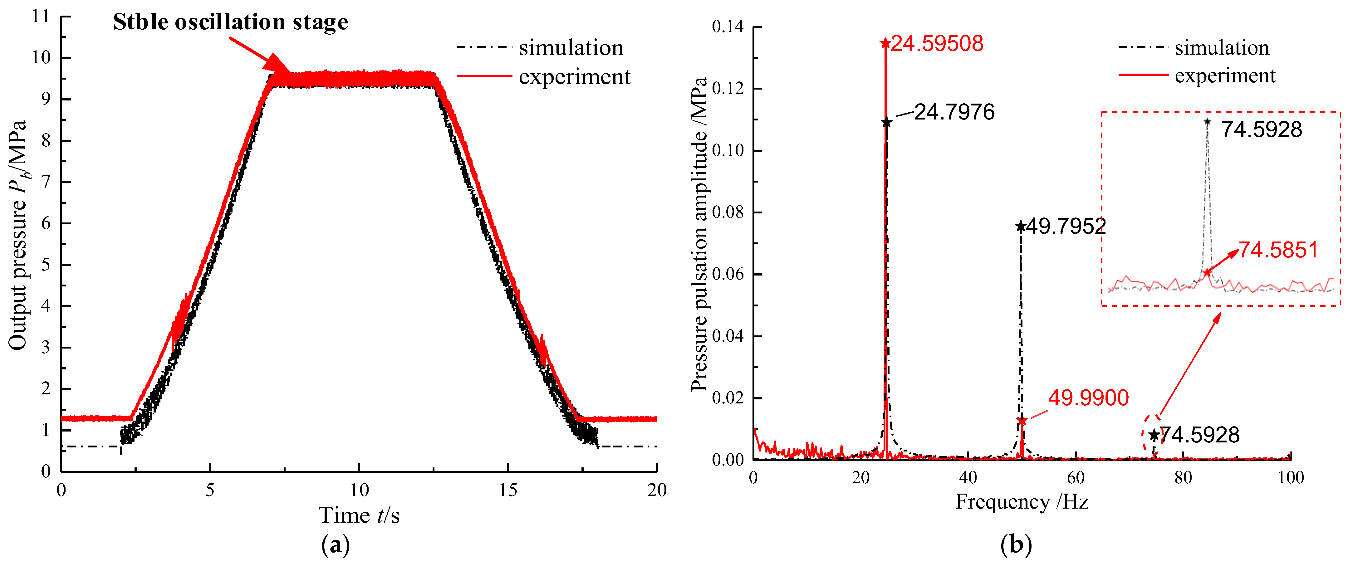
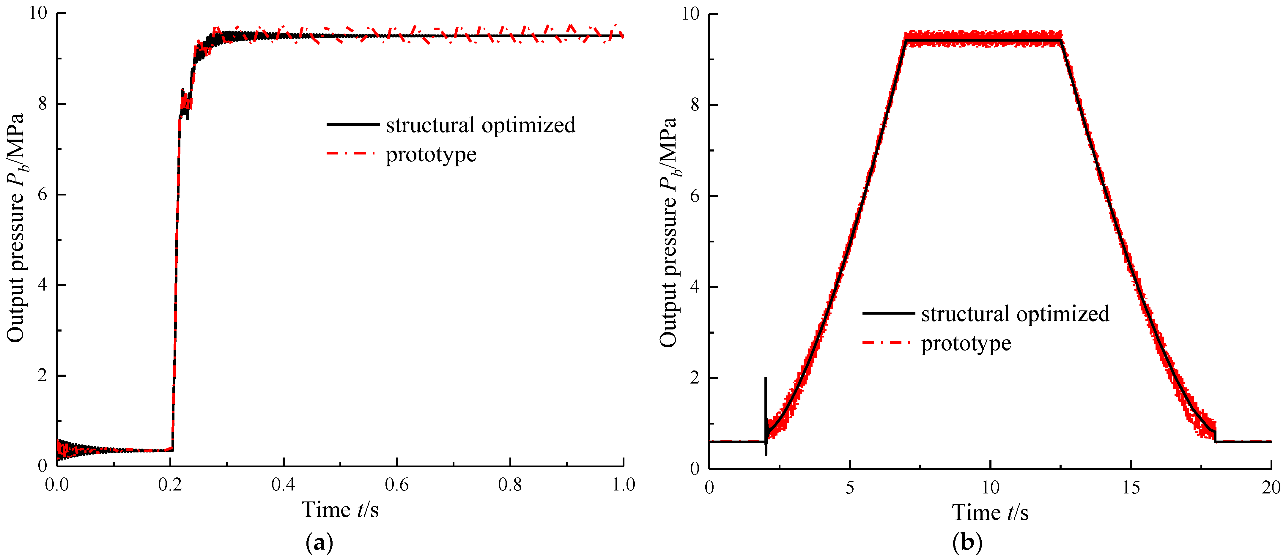
2.3.2. The Comparison between Simulation and Experiment
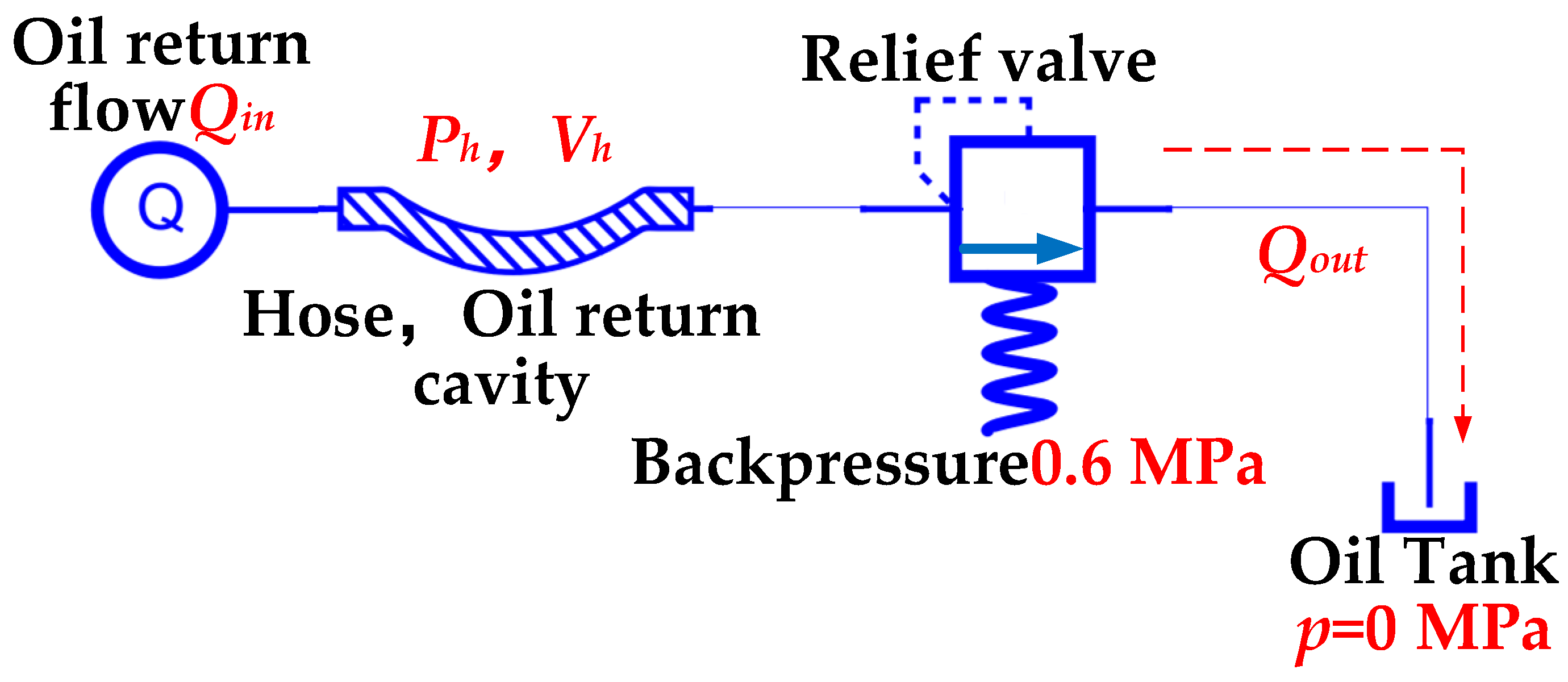
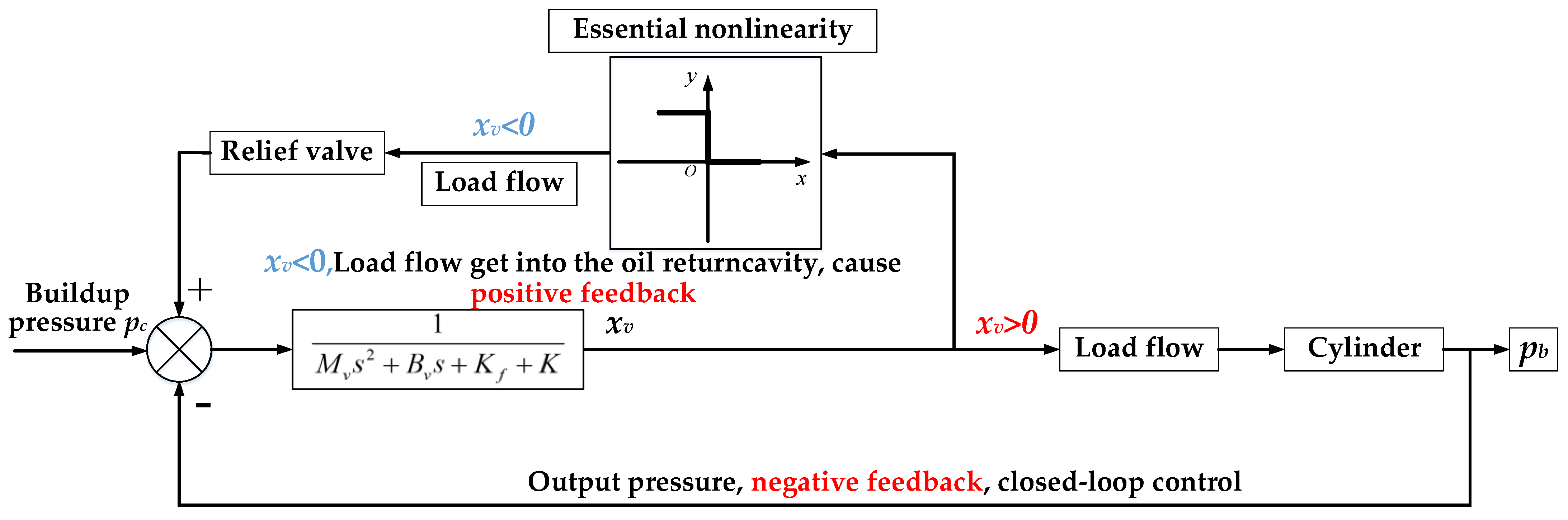
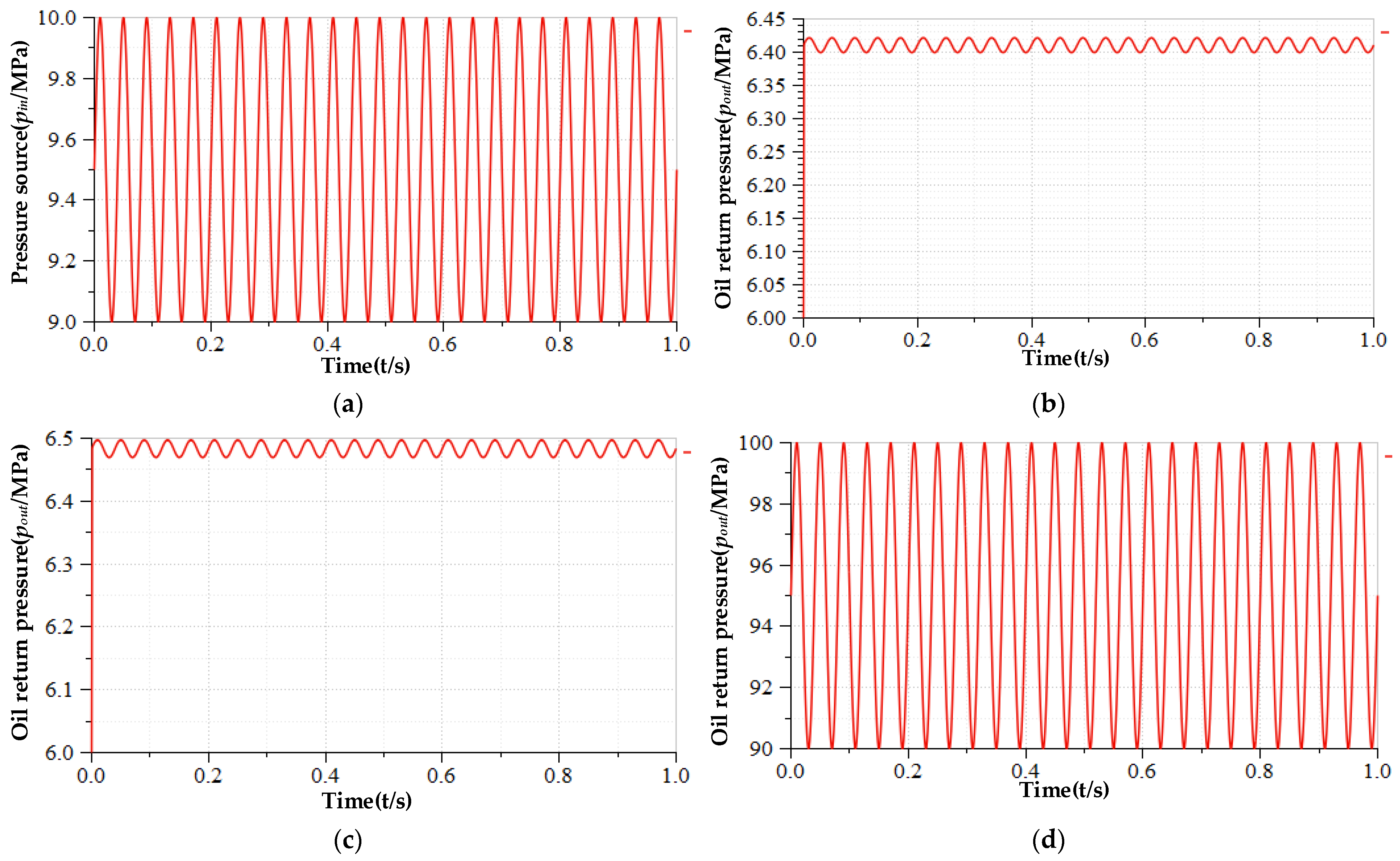
3. Pressure Oscillation Mechanism Analysis
4. Oscillation Suppression of PSVS
4.1. Oscillation Suppression Method
4.2. Verification of Oscillation Suppression Method
4.2.1. Simulation Analysis
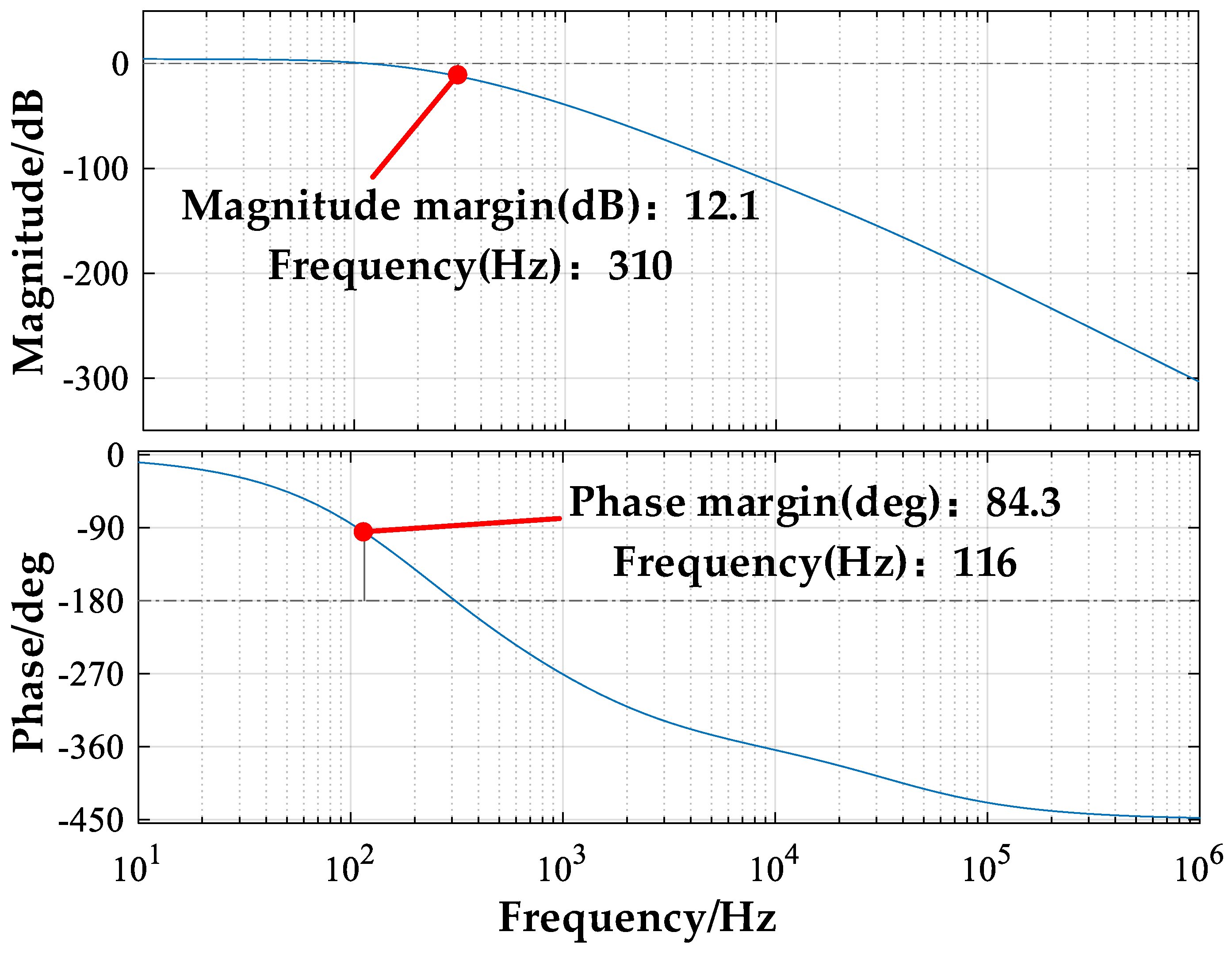
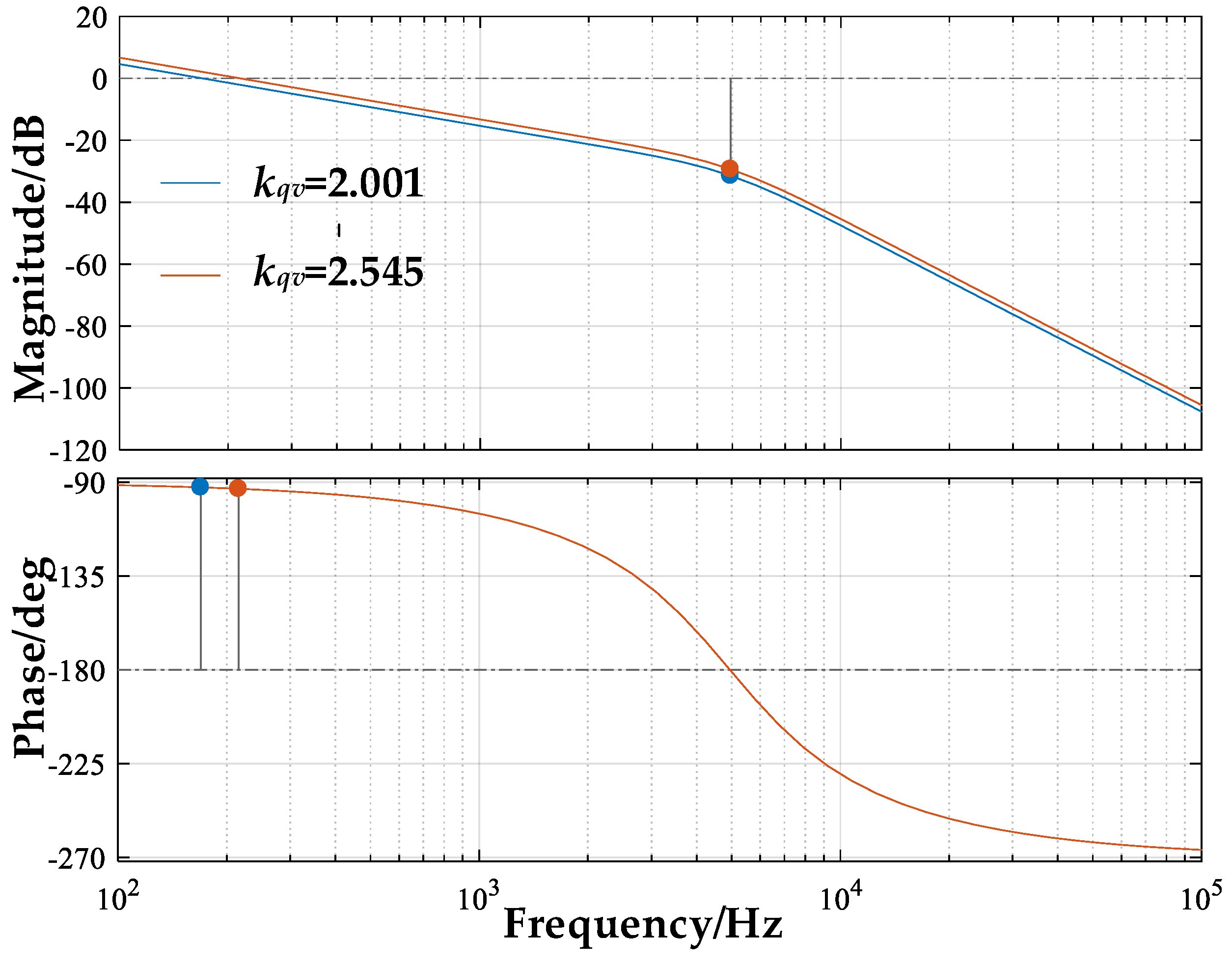
4.2.2. Stability Margin Analysis
5. Conclusions
Author Contributions
Funding
Institutional Review Board Statement
Informed Consent Statement
Data Availability Statement
Conflicts of Interest
References
- Viscardi, M.; Arena, M.; Cerreta, P.; Iaccarino, P.; Inserra, I.S. Imparato, Manufacturing and Validation of a Novel Composite Component for Aircraft Main Landing Gear Bay. J. Mater. Eng. Perform. 2019, 28, 3292–3300. [Google Scholar] [CrossRef]
- Viscardi, M.; Arena, M.; Cerreta, P.; Iaccarino, P. Design and prototyping of a novel composite architecture for a wide-body landing gear bay. Mater. Today Proc. 2021, 34, 288–292. [Google Scholar] [CrossRef]
- Hongling, W.; Guanglai, T.; Longfei, F.; Jinsong, L.; Gang, Q.; Wenqing, Z. Study on Resonance of Braking Pressure Control System of Multi-Wheel and Multi-Strut Aircraft. J. Northwestern Polytech. Univ. 2014, 32, 646–650. [Google Scholar]
- Grinis, L.; Haslavsky, V.; Tzadka, U. Self-Excited Oscillation in Hydraulic Ball Check Valve. World Acad. Sci. Eng. Technol. 2012, 51, 311–314. [Google Scholar]
- Hayashi, S.; Hayase, T.; Kurahashi, T. Chaos in a hydraulic control valve. J. Fluids Struct. 1997, 11, 693–716. [Google Scholar] [CrossRef]
- Misra, A.; Behdinan, K.; Cleghorn, W.L. Self-excited vibration of a control valve due to fluid–structure interaction. J. Fluids Struct. 2002, 16, 649–665. [Google Scholar] [CrossRef]
- Ye, Q.F.; Yan, S.J.; Chen, J.P.; Chen, Z.J. Self-excited Vibration in a Pneumatic Pilot-operated Solenoid Valve. J. Mech. Eng. 2010, 46, 115–121. [Google Scholar] [CrossRef]
- Liu, S.; Liu, H.J.; Xu, H.H. Research of self-oscillation characteristics of check valve flow-path system. J. Rocket. Propuls. 2011, 37, 1–5. [Google Scholar]
- Wang, J.Z.; Chen, E.F.; Yu, W.J. Mechanism of self-excited vibration and dynamic stability for pneumatic valves. J. Aerosp. Power 2014, 29, 1490–1497. [Google Scholar]
- Yan, Y.B.; Zheng, Y.P. Thermal Vibration Characteristics of Torque Motor of Jet Pipe Servo Valve. Fluid Power Transm. Control. 2016, 5, 7–11. [Google Scholar]
- Jiang, W.; Zhu, Y.; Yang, C. Study on Nonlinear Dynamics Behavior of a Hydraulic Relief Valve. China Mech. Eng. 2013, 24, 2705–2709. [Google Scholar]
- Zhang, Q. Research on System Dynamic Characteristics and Oscillation Suppress Methods of Aircraft Braking Hydraulic System; Yanshan University: Qinhuangdao, China, 2022. [Google Scholar]
- Wang, C. Hydraulic Control System; China Machine Press: Beijing, China, 1998. [Google Scholar]
- Wang, Z. Modern Electro-Hydraulic Servo Control; Beihang University Press: Beijing, China, 2015. [Google Scholar]

| Parameter | Definition | Unit |
|---|---|---|
| Δi | Input current | mA |
| Kt | Electromagnetic moment coefficient | Nm/rad |
| Km | Magnetic torque spring stiffness | Nm/rad |
| ψ | Jet pipe rotation angle | rad |
| Ja | Rotational inertia of jet pipe | kg·m2 |
| Ba | Damping coefficient of jet pipe | Nm/rad/s |
| Ka | Stiffness of jet pipe | Nm/rad |
| Kfg | Stiffness of the feedback rod | N/m |
| r | Distance from feedback rod rotation center to nozzle | m |
| kq | Linearized flow gain coefficient of jet nozzle | m2/s |
| kc | Linearized flow pressure coefficient of jet nozzle | m3/sPa |
| xs | Displacement of jet nozzle | m |
| xc | Displacement of the second stage spool | m |
| pc | Buildup pressure | Pa |
| ps | Oil supply pressure | Pa |
| ph | Backpressure of the system | Pa |
| ρ | Oil density | kg/m3 |
| β | Volumetric modulus of elasticity of oil. | Pa |
| Vcv | Volume of the control cavity | m3 |
| Ac | Area of feedback valve spool | m2 |
| Kc | Feedback spring stiffness | N/m |
| mc | Mass of the feedback spool | kg |
| Bc | Damping coefficient of the feedback spool | Nm/rad/s |
| Av | Effective area of buildup pressure | m2 |
| pb | Output pressure | Pa |
| Ab | Effective area of output pressure | m2 |
| Ah | Effective area of backpressure | m2 |
| Kf | Steady-state flow force stiffness of main valve spool | N/m |
| xv | Displacement of power stage valve spool | m |
| xv0 | Initial compression of power stage spring | m |
| Mv | Mass of power stage valve spool | kg |
| Bv | Damping coefficient of power stage valve spool | Nm/rad/s |
| K | Spring stiffness of power stage valve spool | N/m |
| Cd | Flow coefficient of main valve spool | - |
| W | Area gradient of the main valve spool | m |
| QL | Load flow | m3/s |
| y | Displacement of cylinder piston rod | m |
| Ag | Effective area of cylinder piston | m2 |
| Vgb | Work cavity | m3 |
| Cb | Leakage coefficient of cylinder | m3/s/Pa |
| Mg | Mass of cylinder piston | kg |
| Bg | Damping coefficient of cylinder | Nm/rad/s |
| Kg | Spring stiffness of cylinder | N/m |
| Vh | Volume of the oil return cavity | m3 |
| Cdj | Flow coefficient of the relief valve | - |
| Qout | Flow of the relief valve | m3/s |
| xj | Displacement of relief valve spool | m |
| D | Valve port diameter of relief valve | m |
| α | Semi-cone angle of valve spool | rad |
| pcj | Relief valve control pressure | Pa |
| Vcj | Volume of the relief valve control cavity | m3 |
| Rc | Impedance of relief valve damping hole | m3/s/Pa |
| Aj | Effective area of relief valve control pressure | m2 |
| Mj | Mass of relief valve spool | kg |
| Kj | Spring stiffness of relief valve | N/m |
| Bj | Damping coefficient of relief valve | Nm/rad/s |
| xj0 | Initial compression of relief valve spool | m |
| kj | Linearized flow gain coefficient of relief valve | m2/s |
| kqv | Linearized flow gain coefficient of main valve spool | m2/s |
| kcv | Linearized flow pressure coefficient of main valve spool | m3/sPa |
| ks | Steady-state flow force coefficient of relief valve spool | N/m/Pa |
| Oil Supply Pressure | System Flow | Output Pipe (m) | Oil Return Pipe (m) | Backpressure | Load Stiffness | Load Damping |
|---|---|---|---|---|---|---|
| 15 MPa | 6.25 × 10⁻⁴ m3/s | Φ0.006 × 1.50 | Φ0.006 × 1.01 | 0.6 MPa | 1 × 10⁶ N/m | 50 Ns/m |
| Peak-Peak Value (Mpa) | Main Frequency (Hz) | |
|---|---|---|
| Experiment | 0.319 | 24.9584 |
| Simulation | 0.347 | 24.9764 |
| Error | 8.8% | 0.072% |
| Diameter | Length | Diameter of Inlet Runner | Model | |
|---|---|---|---|---|
| Thin-walled | 1 mm | -- | 2 mm | |
| Thick-walled | 1 mm | 10 mm | 2 mm |
| Magnitude Margin (dB) | Phase Margin (deg) | |
|---|---|---|
| Kqv = 2.001 | 31.4 | 87.5 |
| Kqv = 2.545 | 29.4 | 86.8 |
Publisher’s Note: MDPI stays neutral with regard to jurisdictional claims in published maps and institutional affiliations. |
© 2022 by the authors. Licensee MDPI, Basel, Switzerland. This article is an open access article distributed under the terms and conditions of the Creative Commons Attribution (CC BY) license (https://creativecommons.org/licenses/by/4.0/).
Share and Cite
Huang, J.; Zhang, Q.; Zhao, F.; Liu, X.; Wang, T. Analysis and Suppression of Self-Excited Oscillations in Pressure Servo Valve System. Appl. Sci. 2022, 12, 8477. https://doi.org/10.3390/app12178477
Huang J, Zhang Q, Zhao F, Liu X, Wang T. Analysis and Suppression of Self-Excited Oscillations in Pressure Servo Valve System. Applied Sciences. 2022; 12(17):8477. https://doi.org/10.3390/app12178477
Chicago/Turabian StyleHuang, Jian, Qiwei Zhang, Fan Zhao, Xiangyu Liu, and Tianyi Wang. 2022. "Analysis and Suppression of Self-Excited Oscillations in Pressure Servo Valve System" Applied Sciences 12, no. 17: 8477. https://doi.org/10.3390/app12178477
APA StyleHuang, J., Zhang, Q., Zhao, F., Liu, X., & Wang, T. (2022). Analysis and Suppression of Self-Excited Oscillations in Pressure Servo Valve System. Applied Sciences, 12(17), 8477. https://doi.org/10.3390/app12178477