1. Introduction
Currently, the Unmanned Aerial Vehicle (UAV) market is snowballing—thanks to many successful civilian and military applications, including, but not limited to photogrammetry [
1], remote inspection [
2], parcel delivery [
3], disaster recovery [
4,
5], etc. Most UAV missions will benefit from extending the drone range as much as possible while maintaining the Vertical-Take-Off-and-Landing (VTOL) capability. We may consider medical supplies [
6], Search-And-Rescue (SAR) operations [
7,
8], and even non-critical missions such as ordinary remote inspection of distant objects (e.g., wind turbines) or simple parcel delivery.
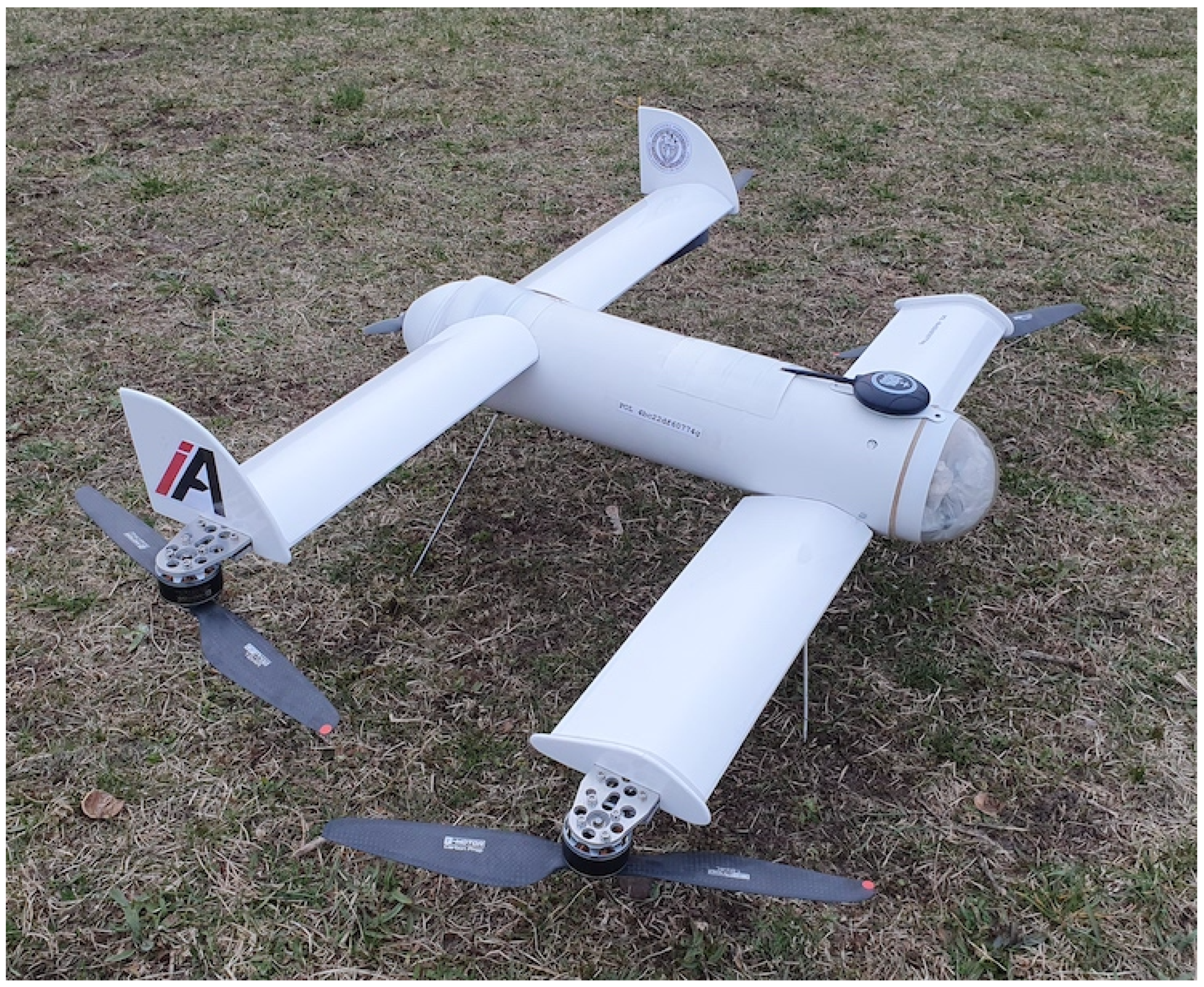
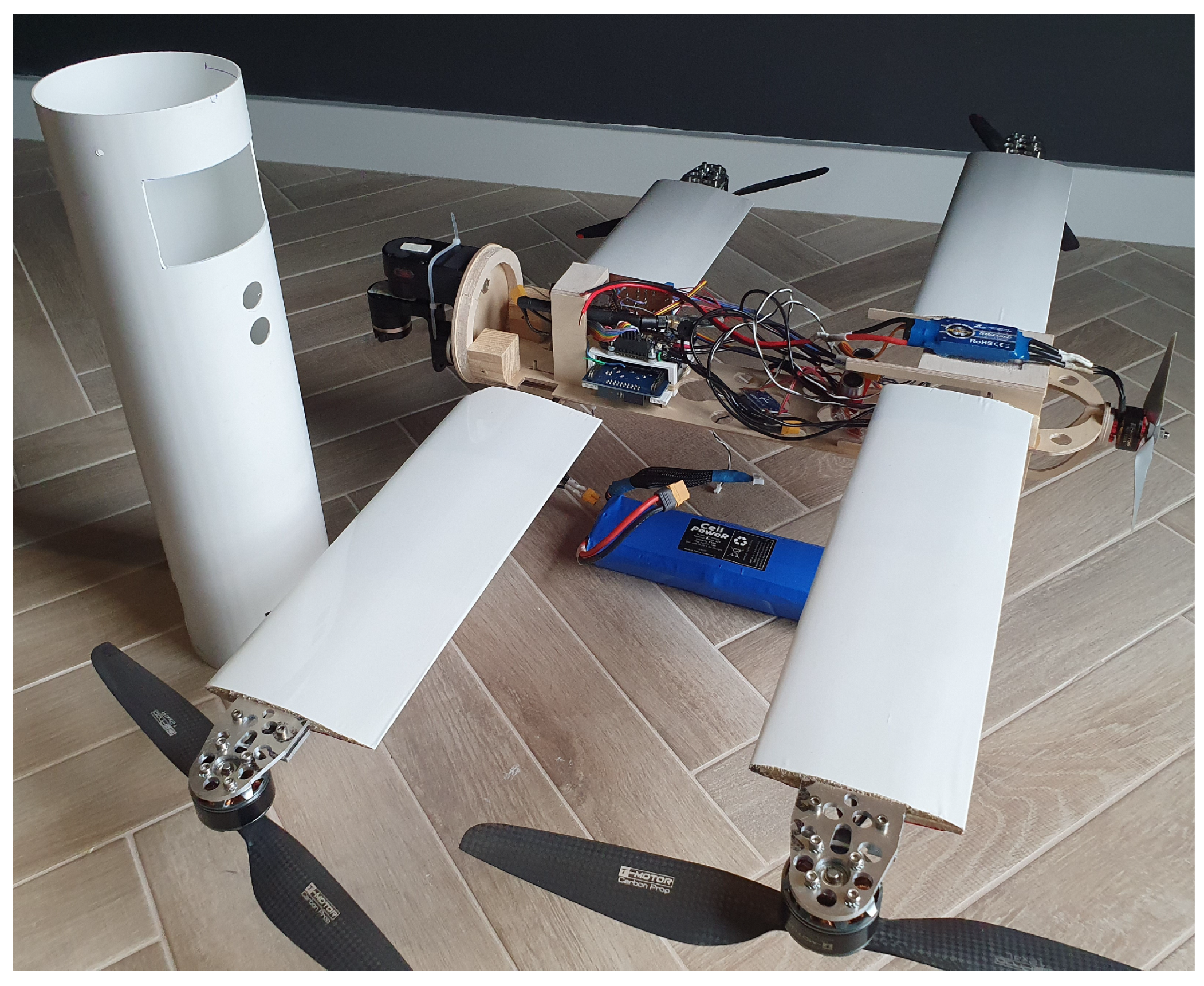
In this paper, we make the following contribution: we investigate a rare type of UAV (
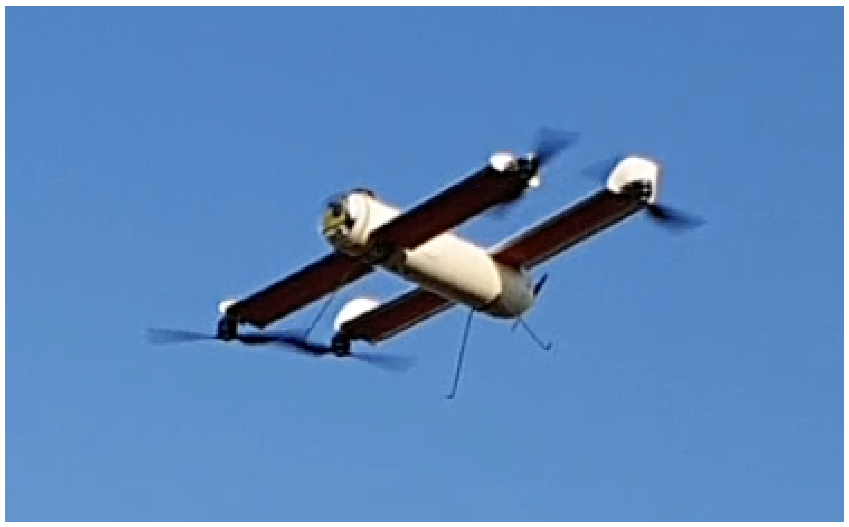
Figure 1), designed for a mission where a small-sized, agile, long-range VTOL drone is capable of precise hovering over a distant target. Many aspects of the drone are discussed, including, but not limited to test flight results (
Figure 2 and
Figure 3). We define the size and weight constraints as follows: a ready-to-fly drone should fit into a square of
m and weigh less than 3 kg (without payload). It should be able to carry at least 300 g of payload and stay airborne for at least 15 min. This research aims to design, build, and test a UAV with maximized range and hovering time.
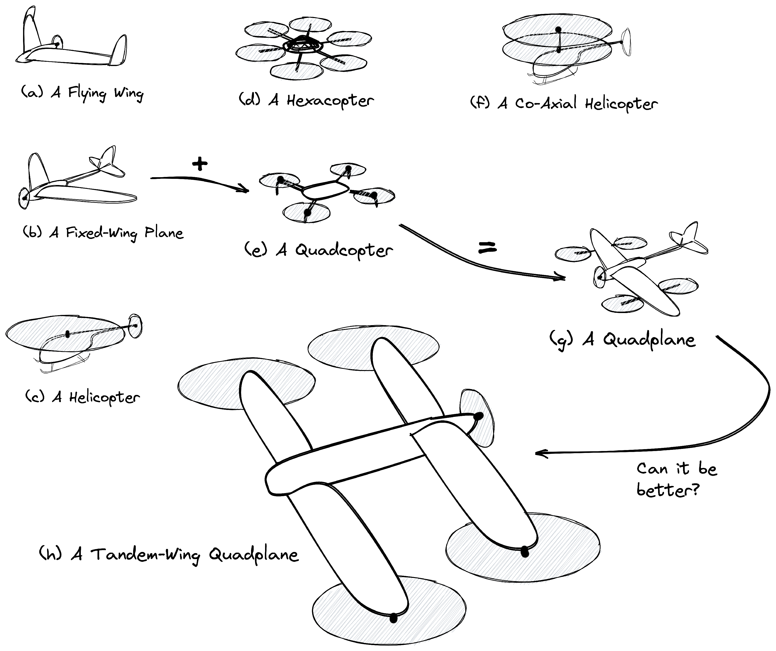
There are many different types of UAVs, each having unique features.
Figure 4 presents the most common configurations:
- (a)
A flying wing [
9,
10]—typically used for long-endurance missions, e.g., photogrammetry or aerial photography. It is not a VTOL drone.
- (b)
A fixed-wing plane [
11,
12]—similar applications as for a flying wing. Fixed-plane UAVs are usually bigger and can carry more payload. If the plane has landing gear, it can operate from a runway. Again, it is not a VTOL drone.
- (c)
A helicopter [
13,
14]—can fulfil VTOL missions when a heavy payload is required. Complex mechanical design, many moving parts, and inefficient due to the energy required for the tail rotor, which does not contribute to the lifting force.
- (d)
A hexacopter [
15,
16]—similar applications to the helicopter. Especially popular in aerial photography, the film industry, and crop spraying. Less complex design; typically, it has no moving parts except the motors and propellers. It can survive if one motor or propeller is lost.
- (e)
A quadcopter [
12,
17,
18,
19]—the most popular type of non-professional UAV. It is very robust and agile; it can be tiny, as well as bigger and more powerful. Usually, it has a limited range because its electric propulsion always comprises lifting force (static thrust) and manoeuvrability (pitch-speed).
- (f)
A co-axial helicopter [
20,
21]—a rare type of UAV. It basically has the same features as a helicopter, except there is no tail rotor; thus, it is more energy-efficient. However, double main rotors mounted on a long shaft make it prone to wind gusts.
- (g)
A quadplane [
22,
23,
24]—combines the benefits of a VTOL quadcopter with all features of a fixed-wing plane. The drawbacks include higher take-off mass and increased drag due to extra motors and motor holders or additional motor tilting mechanics. The wings and the tailplane make this type of drone less agile in hover and more prone to wind gusts.
- (h)
A tandem-wing quadplane—combines essential advantages of VTOL and fixed-wing UAVs. There are a few full-scale designs, and prototypes [
25,
26] mainly use multiple motors to hover (e.g., 6, 8, 12, or more). Existing tandem-wing drones mostly use a tilt-motor [
22,
27,
28] or tilt-wing design [
24,
29]. We decided to select this type of UAV because it has no extra motor holder beams (the two wings support the motors), and it can have a smaller wingspan than a quadplane with a comparable wing surface. It is agile in hover because it acts almost like a regular quadcopter. Thanks to the wings and the pusher motor, it can fly fast in a level flight without using significant energy. Furthermore, all its electric propulsion can be optimized for a single role: four main motors for hover conditions (high static thrust) and the pusher motor for fast level flight (high pitch-speed).
2. Materials and Methods
2.1. Selecting the Drone Type and Its Design Details
The need to start and land vertically implies choosing one of the rotorcraft vehicle types. A multirotor, especially a quadcopter, seems to be a better choice than a classic helicopter. A helicopter has many more complex mechanical elements (e.g., main rotor head, a swashplate, pushrods). In contrast, the quadcopter has just four motors with fixed propellers and no moving parts at all. There are two ways of reaching a distant target by a quadcopter: fly fast and drain the battery quickly or stay mid-air longer, but fly at a slower speed. In both cases, flying forward causes more significant electric energy consumption than hovering. However, adding wings and a propulsion system dedicated (and optimized) for a forward flight might increase the drone’s range (a drawback: adding some extra weight). We wanted to keep the drone small and agile. We finally decided to research a rare tandem-wing configuration rather than a typical quadplane. Such a design allowed us to increase the wing area without exceeding size constraints and minimize structural support elements—the wings could become the quadcopter motors’ holders. The tandem-wing (i.e., a lifting-tail) airplane can have its centre of gravity more aft than a regular tail plane. That is beneficial from the quadcopter point of view because the main motors are loaded more evenly.
We decided to use a pusher motor as the propulsion system for the level flight to avoid drag produced by the propeller wake. The four main propellers’ wake could introduce strong turbulence over the wingtips; therefore, we moved the motors below the wings.
2.2. Electric Propulsion
A helpful rule of thumb is that one starts with the electric propulsion design first because it is easier to match the mechanical design of the fuselage to known components’ sizes and weights. That is especially important for the battery pack—usually the heaviest and largest element.
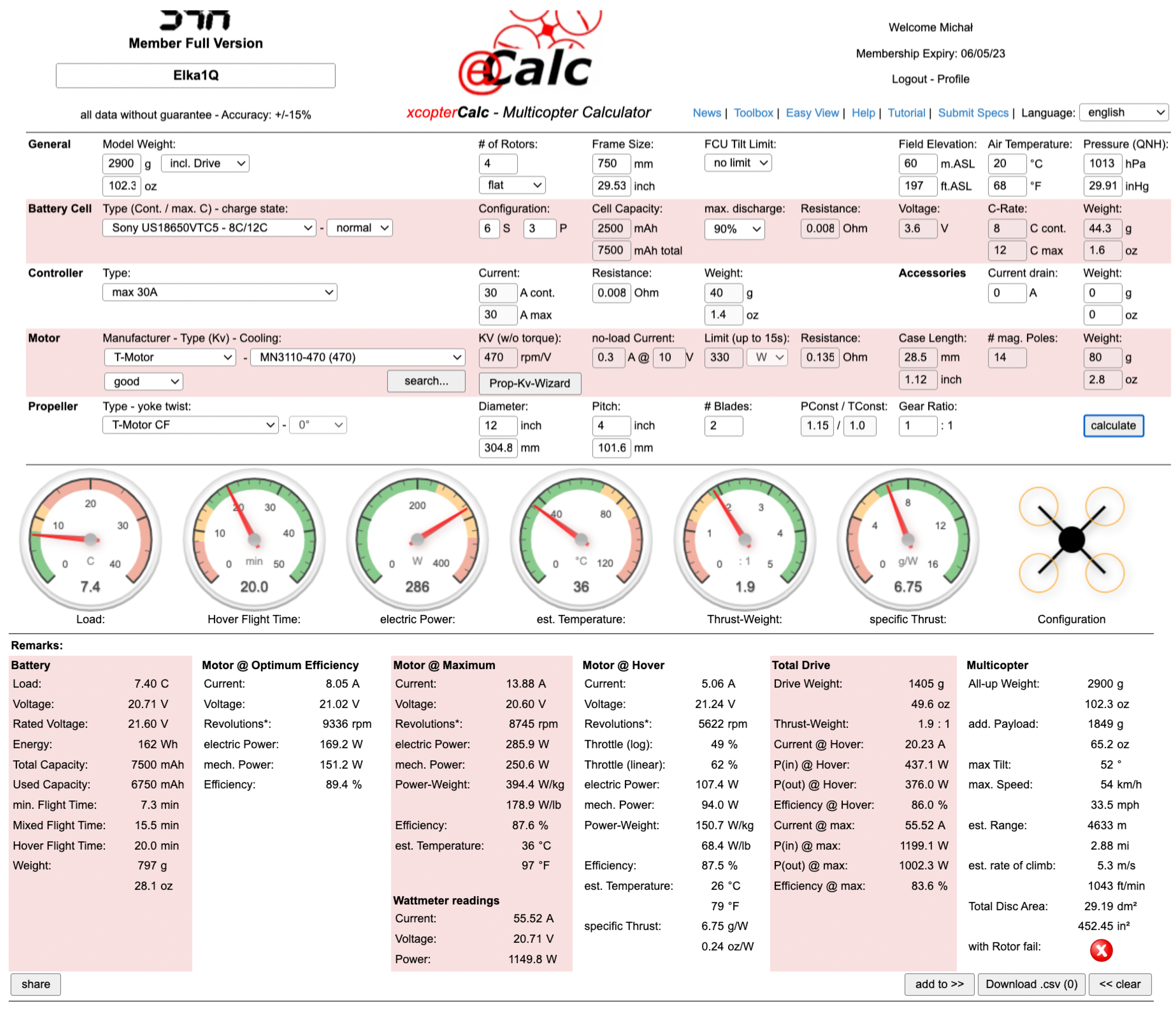
At the time of writing, the eCalc [
30] seems to be the best and most accurate tool, including, but not limited to finding the best motor–propeller–battery setup (see
Figure 5 and
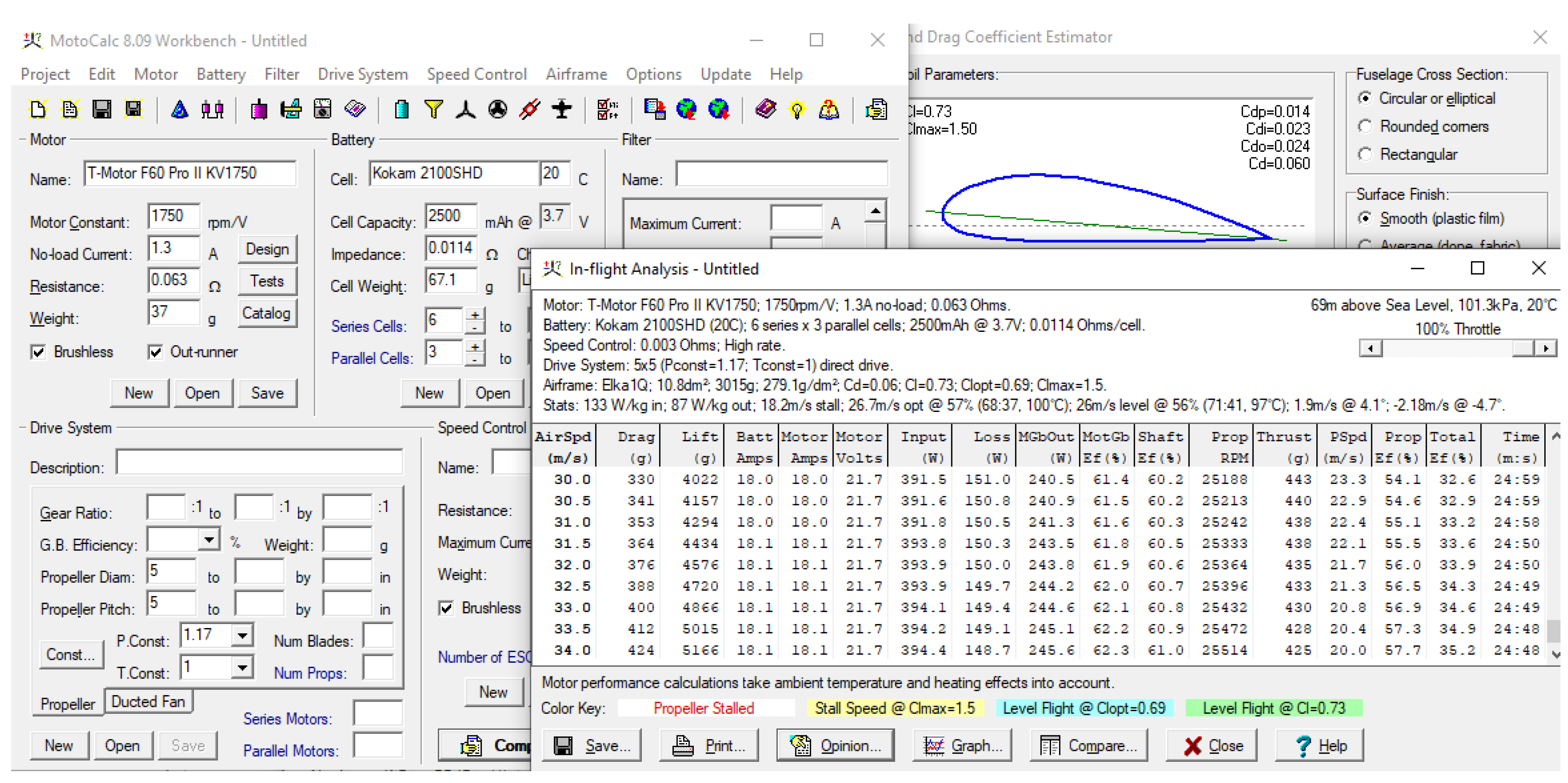
Figure 6). Another great tool, especially for predicting electric RC plane performance, is MotoCalc [
31]. We used it for detailed pusher propulsion performance prediction, e.g., to estimate top speed in level flight and find the stall speed for various wing setups (see
Figure 7). Considering the general assumptions mentioned in
Section 1, we decided to look for high-D/P-ratio propellers (diameter-to-pitch ratio), a high-voltage setup, and lithium-ion batteries rather than lithium-polymer ones. A propeller with a high D/P ratio provides great static thrust (a lift force in the case of a drone), but the thrust drops suddenly when the airspeed increases. That phenomenon, however, may impact drone manoeuvrability. Typically, fast and agile drones (e.g., racing quadcopters) use the D/P ratio in the range
, where propellers with D/P close to 1 (e.g.,
) allow high-speed flights, but consume much energy in hover. A high-voltage setup decreases the current needed (assuming a constant total output power)—lower current benefits in thinner electric wires, and smaller Electronic Speed Controllers (ESCs), thus a more lightweight setup. The Li-ion batteries usually offer greater capacity than Li-poly batteries of the same weight, but cannot work in high-current load conditions. The final setup of the quadcopter’s electric propulsion is presented in
Figure 5 and
Table 1, and the predicted performance of the drone (and its range) can be found in
Figure 6. Predicted stall speed, top speed, and the total flight time can be found in
Figure 7. A summary of the predicted performance is presented in
Table 2.
2.3. Mechanical Design
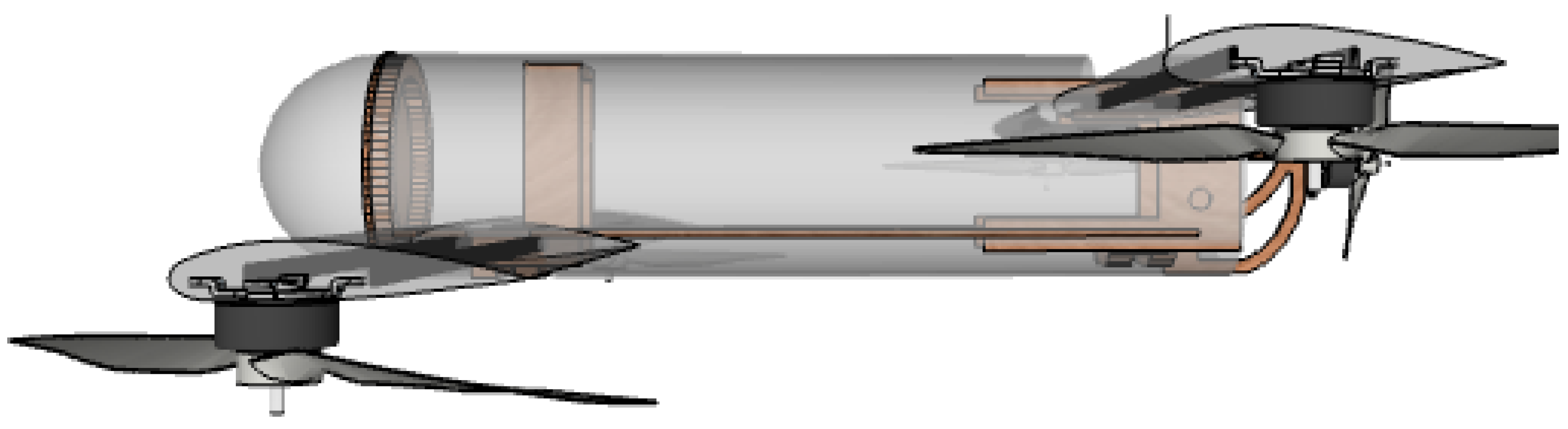
The overall shape of the drone (as seen in
Figure 8 and
Figure 9) is a compromise among the general assumptions (described in
Section 1), size and weight of significant components (such as the battery pack), and smart usage of available materials.
2.3.1. Wings
Typically, drone arms are made of carbon-fibre tubes because they are very stiff and lightweight at the same time. However, such a single tube could have a too big a diameter to fit into the drone’s wing. Instead, we decided to use double
mm carbon-fibre flat bars as wing spars. Additionally, the space between them forms a convenient tunnel for electric wires. The wings are built of two matching full-balsa wood elements: a bottom and a top half, both CNC 3D milled and glued together. The leading and trailing edges of a wing are usually prone to accidental damage (especially a very thin trailing edge); therefore, both edges are reinforced with carbon-fibre
mm flat bars. The carbon-fibre wing spars at the wingtips support the main motor holders (CNC milled from a 3mm-thick aluminium sheet). The two elements of the holders are screwed together to catch protruding wing spars tightly. Finally, the surface of the wing is covered by Oracover [
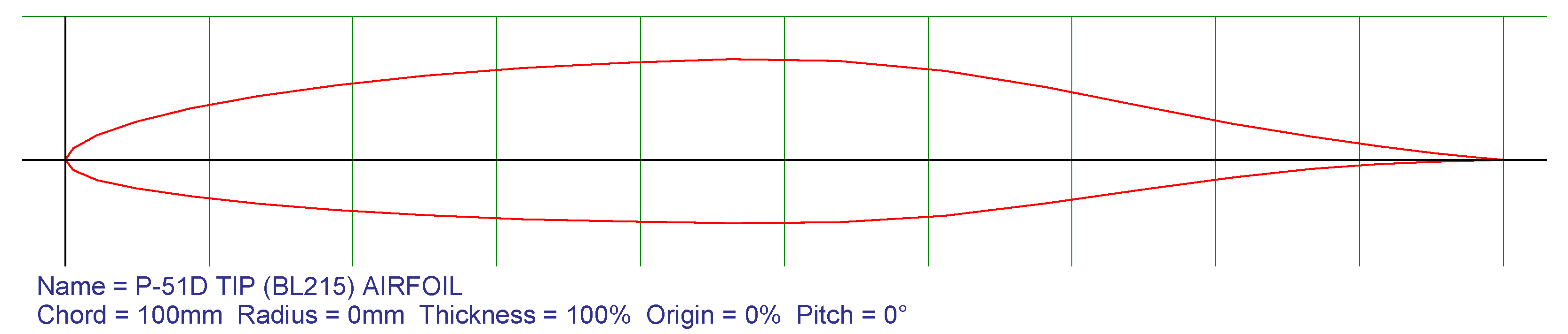
32] film. The wing construction proves to be light and very durable. We could say it is a perfect balance between stiffness and elasticity. Initially, we chose a wing profile (an airfoil) optimized for high-speed flight: the P-51D tip (BL215) airfoil (see
Figure 10). Generally speaking, high-speed airfoils have low drag, but, on the other hand, have a low lift coefficient, which results in a high stall speed, and that means the plane has to maintain high enough speed to stay airborne in a level flight. That should not be an issue if the pusher motor can accelerate the drone to that speed. Due to safety reasons, we decided to modify the original wings—we made them much thicker (see
Figure 11). Such a thick airfoil (thickness increased from 12% to 25% of the airfoil chord) gives us a much higher lift coefficient (resulting in a lower stall speed) at the cost of lowering the top speed. Nevertheless, lower stall speed means we could perform the in-flight experiments of switching between quadcopter and plane mode at lower (i.e., safer) speed, and we could do that in a less spacious airfield.
The wing configuration used in the drone is called a “tandem-wing” or sometimes a “lifting-tail plane”. Those names refer to the fact that the aft wing is not just a horizontal stabilizer, like in a classic “tailplane” configuration, but it contributes to the total lift force produced by the plane. It is a rare configuration due to possible stability and controllability issues [
34,
35]. Sometimes, quite the opposite statements can be found—tandem-wing planes are easier to pilot because of safer stall behaviour [
36]. However, there were at least a few successful tandem-wing planes, e.g., Quickie designed by Elbert Leander “Burt” Rutan (and later QAC Quickie Q2) [
36,
37] and the Proteus [
38] built by Scaled Composites (Rutan’s company). Another famous tandem-wing plane is the “Flying Flea” (French name: “Pou du Ciel”), designed by Henri Mignet in 1933. A thorough study of many more historical and modern tandem-wing planes and UAVs, as well as their aerodynamic and stability studies, can be found in [
34].
A wing that produces lift force also generates a downwash, i.e., the airflow direction behind the trailing edge of the wing is deflected down by the aerodynamic action of the wing. That phenomenon changes the effective Angle of Attack (AoA) of the rear wing in the tandem-wing configuration. Most tandem-wing planes have the front wing mounted lower than the rear wing to minimize the downwash effect of the front wing [
34,
35]. Additionally, it is recommended to set a higher AoA of the front wing than the aft wing—such a wing setup affects the stall behaviour of the tandem-wing plane. The front wing with a higher AoA will stall first while the aft wing still produces lift force—that situation will cause the plane to pitch down, increase the speed, and ultimately, end the front wing’s stall (bring back its lift force) [
36]. Following the suggestions, the front wing of the Elka1Q drone was mounted at ca. 4° AoA and the aft wing at ca. 2° AoA.
Finally, there is at least one more critical aspect of every aircraft having wings: Centre of Gravity (CG, CoG). It is crucial to keep the longitudinal stability of an aircraft. We used a CG calculator from the eCalc toolset [
30]. The results of the calculation are presented in
Figure 12.
2.3.2. Fuselage
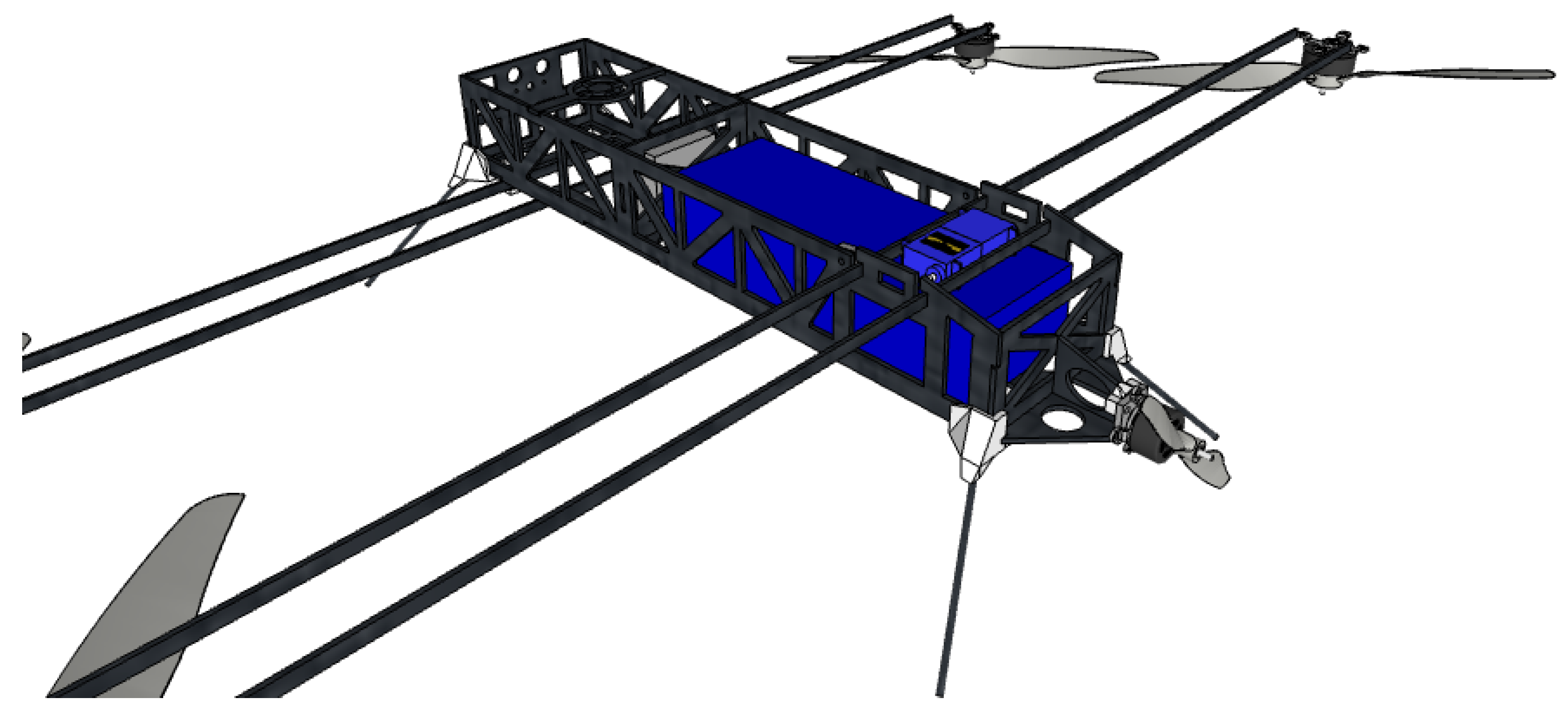
The early design of the fuselage (
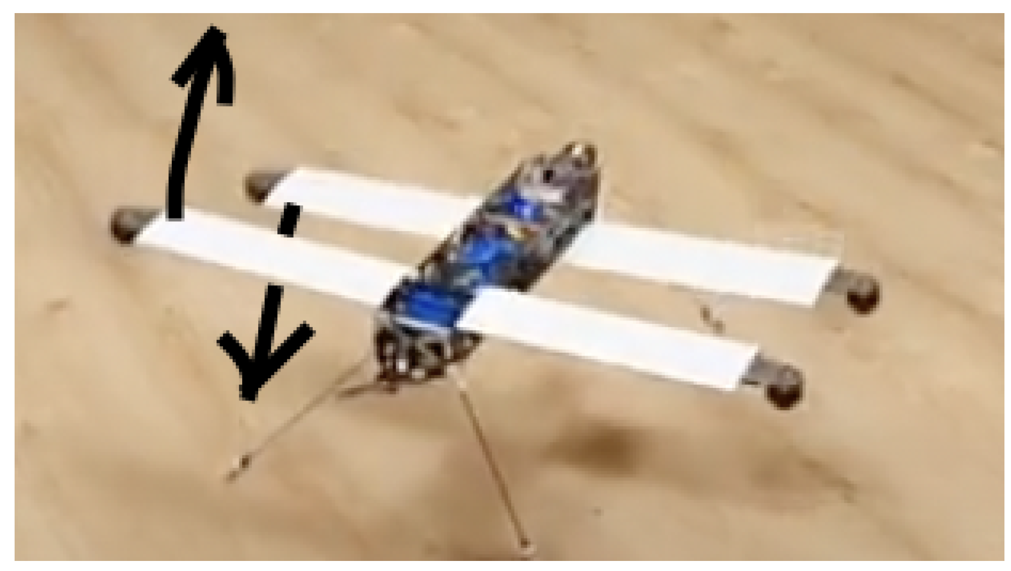
Figure 13) was based on carbon-fibre components (CNC milled from a 2.5 mm-thick CF plate). After a few flight tests, we discovered an issue: the fuselage was twisting about the longitudinal axis, as seen in
Figure 14.
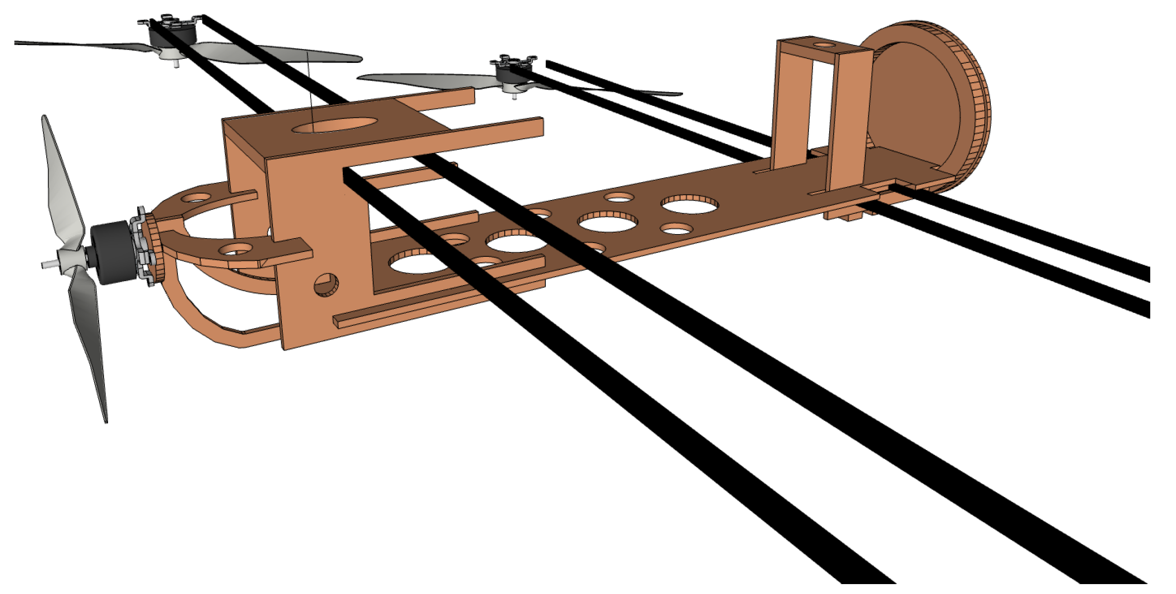
The final fuselage design was based on a rigid PVC tube (100 mm diameter and 1 mm wall) and a lighter, but still solid plywood structure (
Figure 15,
Figure 16 and
Figure 17). The PVC tube acts similarly to a monocoque structure, eliminating the twisting about the longitudinal axis.
The landing gear is non-retractable—we made four fixed legs of 3 mm spring steel wire supported by pinewood blocks at the bottom of the fuselage.
The overall structure of the wings and the fuselage proved to be very rigid and robust, surviving a few serious crash landings. The most significant disadvantage of such a compact construction is complicated maintenance of internal components, e.g., access to electronic boards, wires, and connectors.
2.4. Electronic Systems
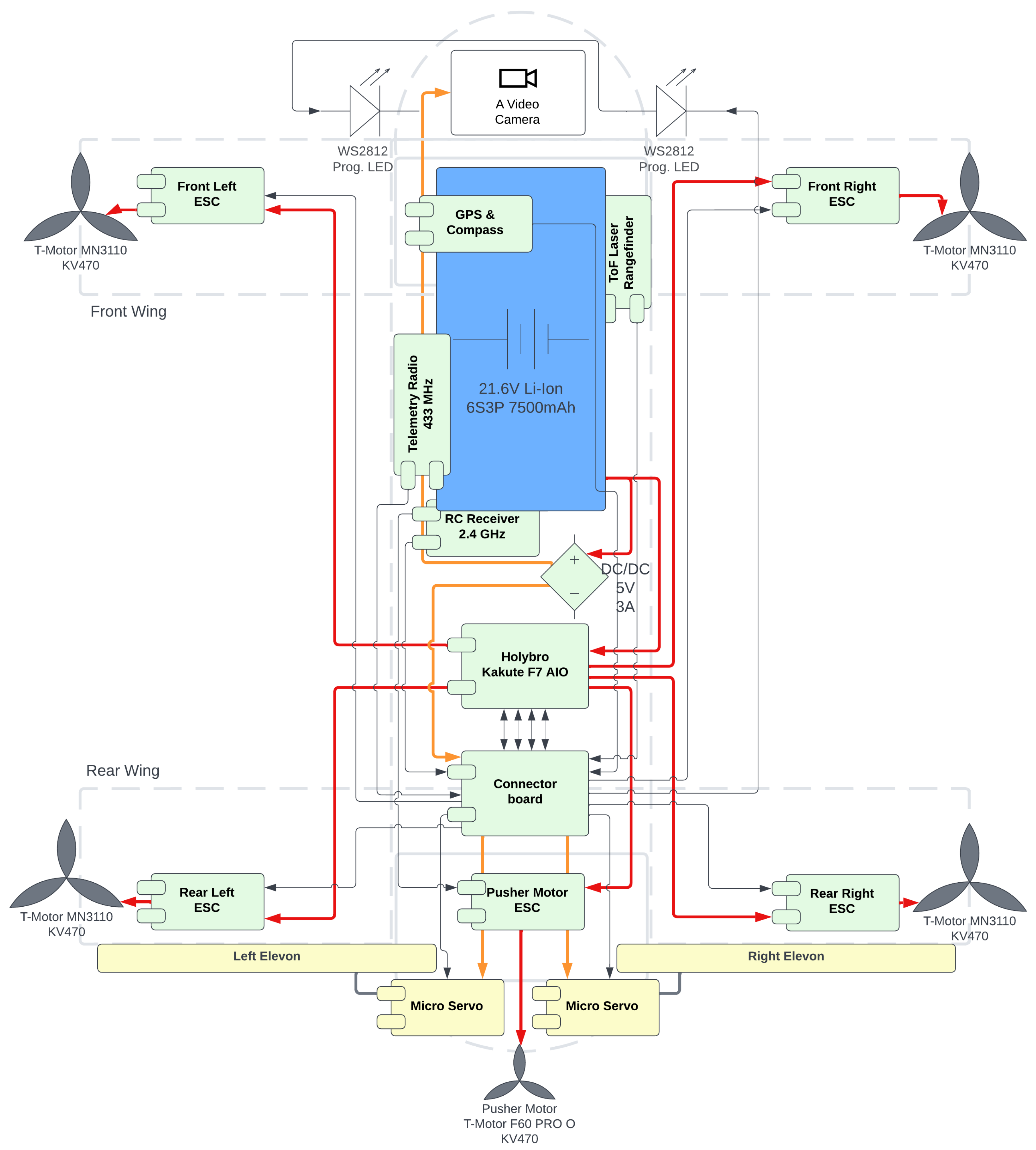
The complete diagram of all electronic components installed in the drone and wirings among them are presented in
Figure 18. We chose the Holybro Kakute F7 AIO [
39] as the central Flight Controller (FC) board—mainly due to its compact size and efficient primary microcontroller (STM32F745). The FC board was attached to the fuselage through vibration dampers—which is crucial for correct onboard Inertial Measurement Unit (IMU) readings.
The wiring diagram (
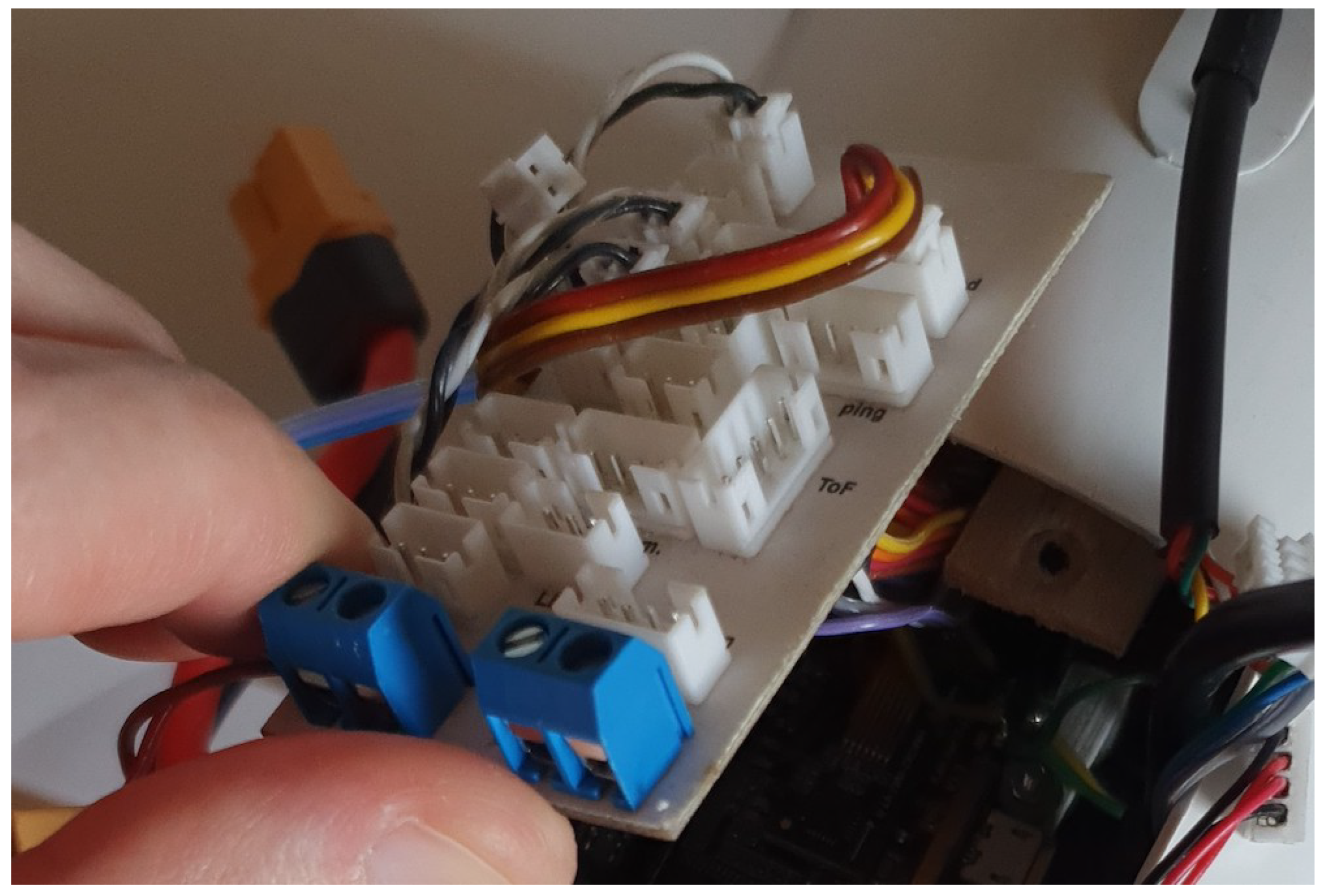
Figure 18) reveals many connections across far drone sections. To simplify the maintenance of the electronic components, we designed a dedicated connector board (
Figure 19). The board exposes all signal sockets and separates the voltage supply for the servos. A separate DC/DC converter provides a 5 V supply for the servos and video camera. The servos could generate dangerous voltage spikes that could interfere, e.g., with the FC or other crucial components. The FC board supplies other components through a built-in 5 V DC/DC converter, which should be free of any voltage spikes. The diagram shows that all power lines go through the FC board because the FC has a built-in current sensor (up to 120 A). It is worth mentioning that the FC has only 6 Pulse Width Modulation (PWM) output channels: four of them are used by the four main quadcopter motor ESCs, and the two elevon servos use the remaining two. Because of the lack of another PWM output, the pusher motor ESC is connected directly to the Radio Control (RC) receiver. We used a Futaba T14SG transmitter and a Futaba R7008SB receiver to pilot the drone. The receiver has the S.Bus output—a single connector to send all 14 channels to the FC board. A 3DR radio transceiver (433 MHz) was used for telemetry and autopilot commands from the Ground Station (GS). A GPS and compass were placed in a compact module mounted outside the fuselage—to improve GPS signal reception and move the compass away from substantial magnetic field interference induced by the power wires. The FC can communicate its status via programmable LEDs (WS2812)—two such LEDs are mounted in the front section, on both sides of the fuselage. The FC has a built-in barometer for altitude reading. However, the barometer’s accuracy is limited. We planned to install a down-facing rangefinder for a smooth auto-landing feature. Initially, an ultrasonic sensor was tested, but we decided to replace it with a tiny, affordable, and very reliable Time-of-Flight (ToF) laser rangefinder (Pololu VL53L1X [
40]). With its range up to 400cm, the auto-landing mode works perfectly smoothly.
We used good-quality 18 AWG power wires with XT60 and XT30 connectors. For the signal connectors, we used Ninigi NXG-02 [
41] (2mm raster connectors), 2–6 pins, depending on a particular component to connect.
2.5. Control Principles
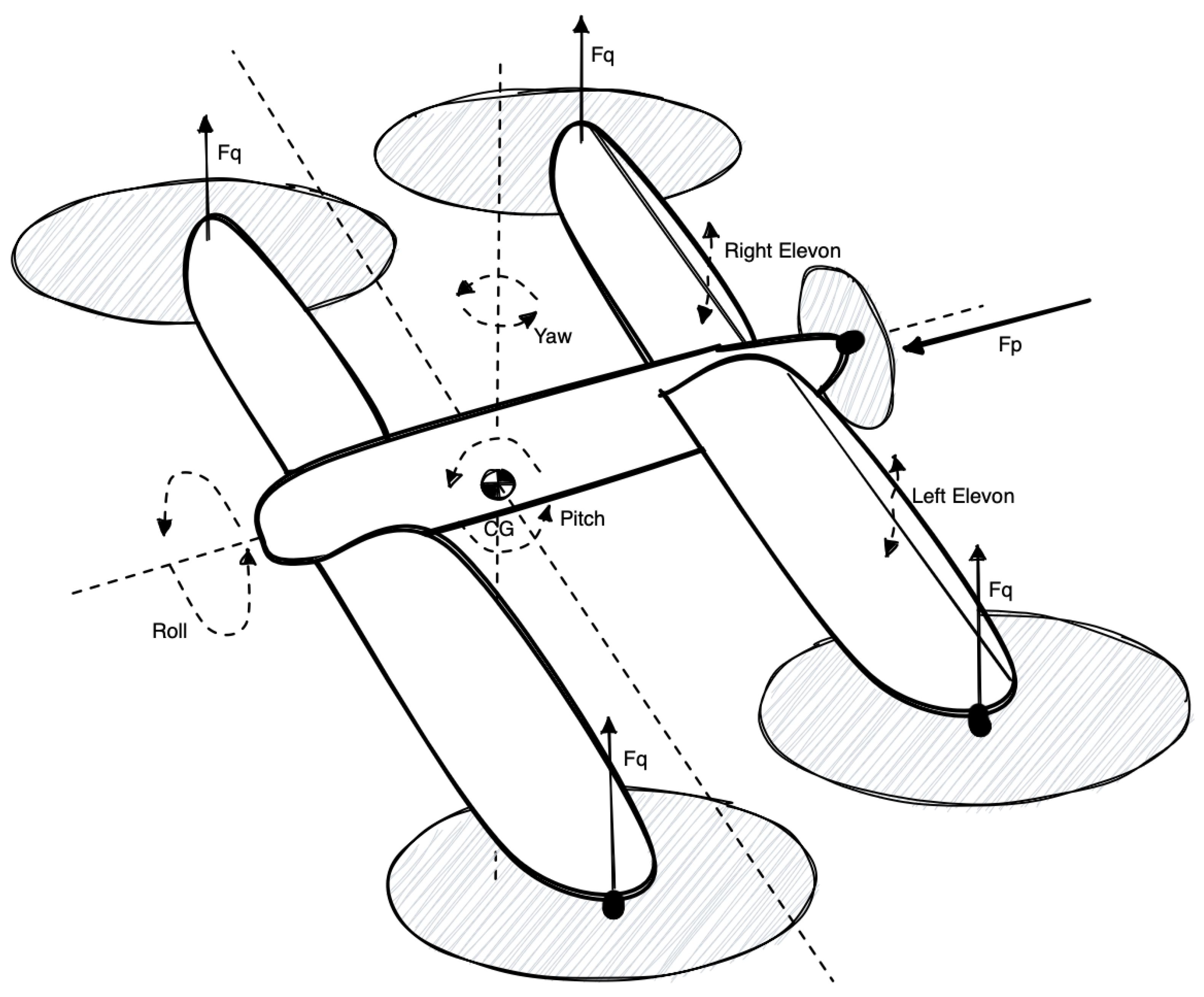
Figure 20 explains the forces acting on the drone’s body and primary axes of rotation. The drone dynamics can be analysed from a quadcopter and a plane point of view. The forces and moments equations can be derived from Euler’s equations for rigid body dynamics—this is thoroughly explained in [
12,
17,
18]. We also explained in our previous paper [
42] how the quadcopter control forces
(see
Figure 20) are mixed to obtain desired moments for the roll, pitch, and yaw axes. Although the quadcopter-like control always actuates all four motors, the control task can be decomposed into isolated controllers for each rotation axis separately [
42]. The
force in
Figure 20 is the forward-directed force produced by the pusher propeller (when the pusher motor is active).
The trailing edge of the rear wing was converted into full-length elevons, i.e., control surfaces that act as an elevator when deflected in the same direction and as ailerons when deflected differentially [
12]. The drone has no rudder, which means that while flying in the plane mode (a level flight using pusher motor and wings’ lift force, quadcopter motors shut down), only rotation around the roll and pitch axes is possible. We decided that such a simplified control should be enough to maintain the horizontal flight and perform basic turns.
2.6. Flight Controller Software
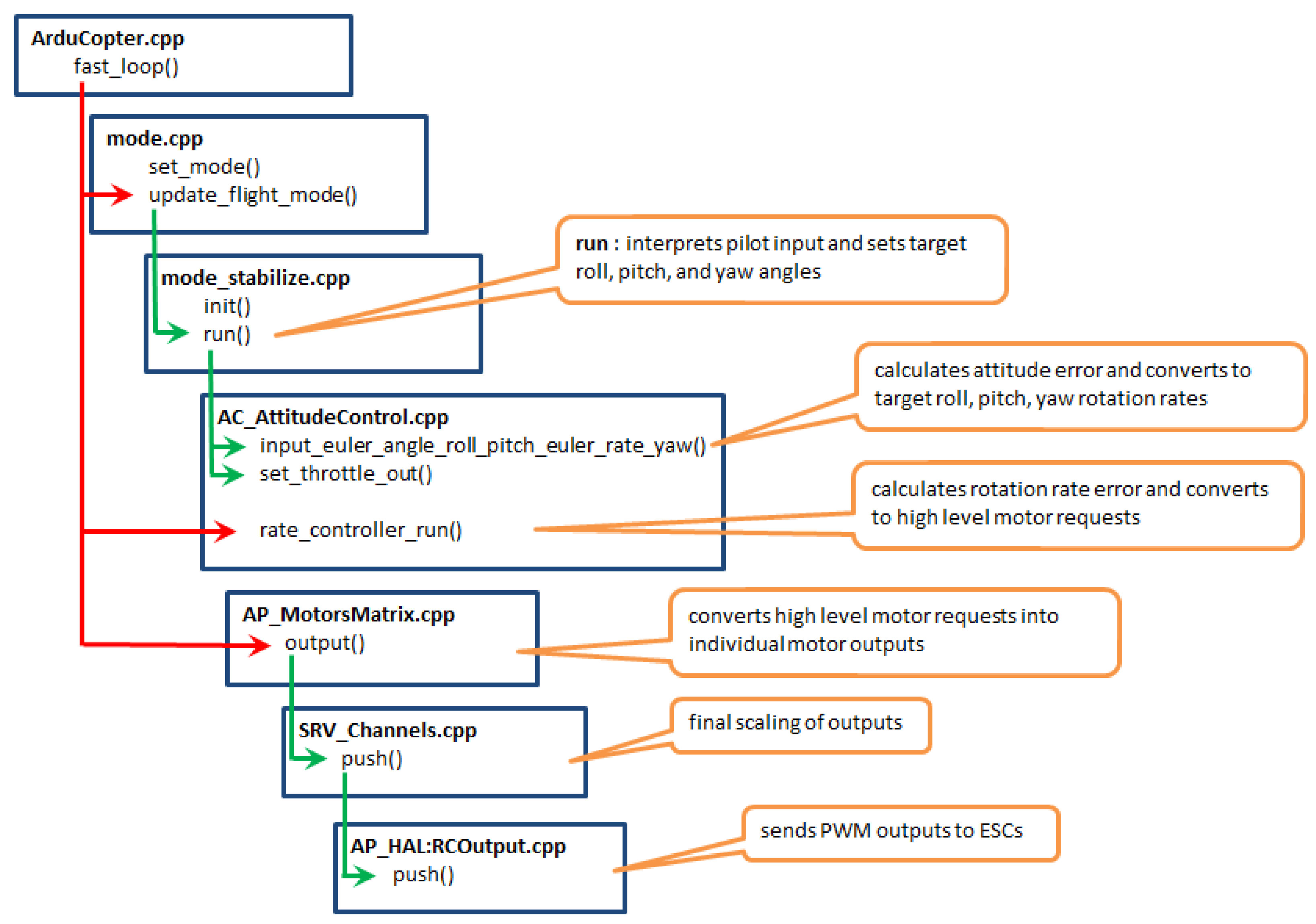
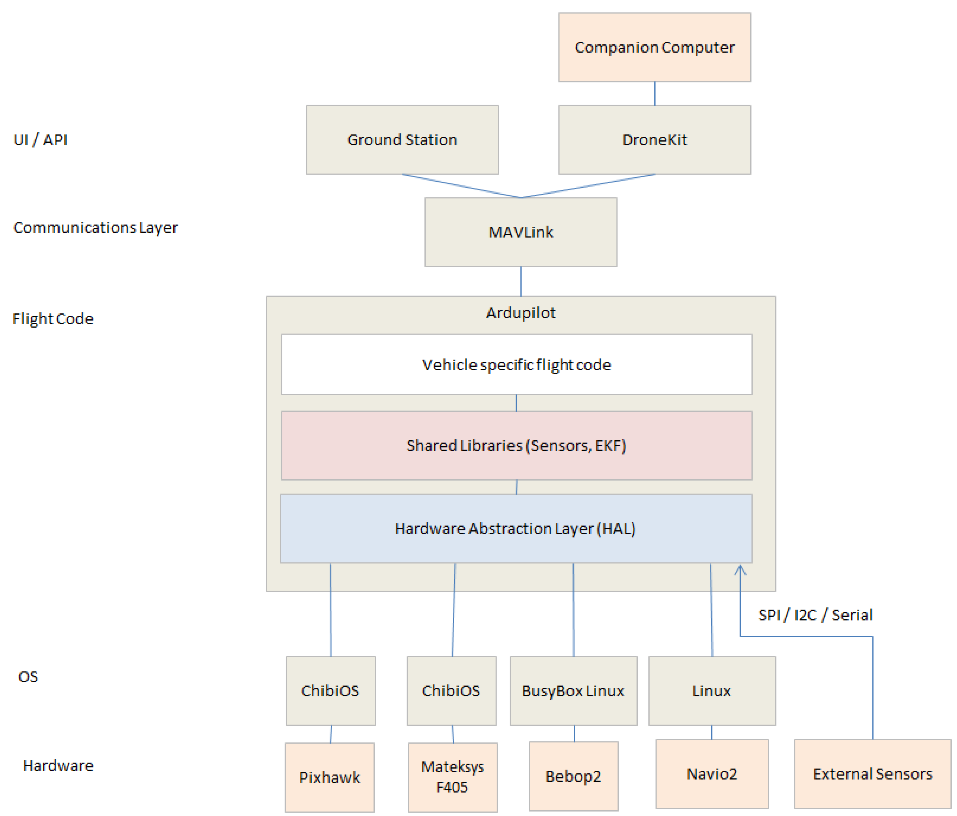
We chose the Kakute F7 AIO as the primary FC because the ArduPilot [
43] software can be compiled and installed on that board. The ArduPilot is a leading open-source autopilot software. It is well tested and greatly supported by a broad community of UAV enthusiasts. We compiled the ArduCopter subset of the ArduPilot stack.
Figure 21 and
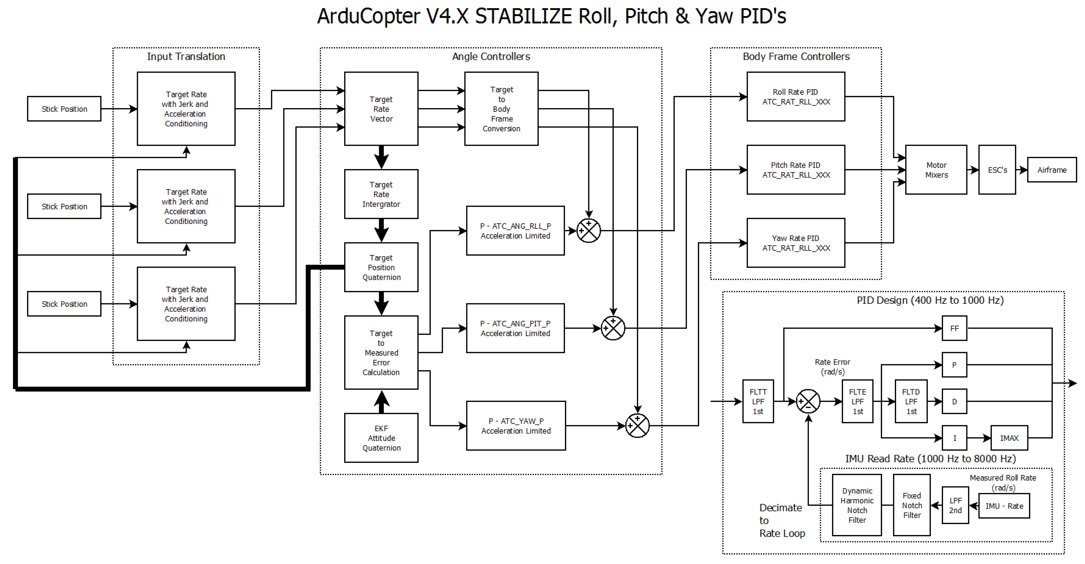
Figure 22 show a high-level overview of the ArduCopter software components. The structure of ArduCopter attitude controllers is shown in
Figure 23. The original attitude controller is a cascade of Proportional (P) and Proportional–Integral–Derivative (PID) controllers [
44] (for each axis separately). Although the original diagram mentions a Feed-Forward (FF) component, it was eventually disabled in our build of the ArduCopter software. We investigated the overall agility of the attitude controller and eventually implemented a novel variant of the Model Predictive Controller (MPC) [
44,
45] as described in [
46]. The control law of the attitude PID controller (see
Figure 23) is simple enough that the embedded microcontroller can compute it efficiently in the main control loop at 400 Hz. However, our MPC controller was computationally heavy and barely fit into the main control loop. An interesting control scheme optimization (event-triggered control scheme) was proposed in [
47,
48]—future research could check how much processor time could be saved without losing attitude stability.
We implemented two new flight modes [
49]: the FixedTestTrajectory and the Elka1Q mode. The former was helpful for model identification and controller tuning (described in detail in our other papers [
42,
50]), and the latter was entirely dedicated to the plane-like flight phase.
Let us consider the flight dynamics of a fixed-wing plane with symmetric elevon control surfaces. When elevons deflect, the plane starts to rotate over its roll or pitch axis, depending on the direction of the elevons’ deflection (to recap: the same direction of deflection leads to pitch rotation, and differential deflection leads to roll rotation). A simplified fixed-wing model can safely assume that the angle of the elevons’ deflection is proportional to the plane rotation speed. Based on that statement, we eventually simplified the Elka1Q mode. When activated, the main quadcopter motors are slowed down to a constant idle speed and no longer actuated. The pitch and roll control signals from the rate controllers (see
Figure 23) are directly translated into the desired elevons’ deflection angles. Such a simplification has advantages: the ArduCopter stabilize mode implements the attitude position and rate (i.e., rotation speed) controllers. Still, it allows control of the target roll and pitch angles via the human pilot’s RC transmitter. Since the drone has not been tested in a wind tunnel, we were not sure how big we should allow for the deflection angles to be for controlling the drone safely. Due to that concern, we implemented a live-tuning (via RC transmitter knobs) of scale coefficients for the output pitch and roll signals, which were fed into the elevons’ mixer.
We decided to intentionally not implement any transition phase—a flip of an RC transmitter switch turns the Elka1Q mode on and off immediately. In our reasoning, we assumed it is safe to accelerate the drone in the regular quadcopter mode because the ArduCopter’s stabilize mode maintains the drone’s attitude in the air (i.e., it keeps the roll, pitch, and yaw tilt angles fixed). When the drone flies fast enough (faster than the estimated stall speed), disabling the quadcopter motors and enabling the elevons should (at least in theory) let it keep roughly the same attitude in the air in an actual on-wing level flight. Similarly, going back to quadcopter mode in a fast forward flight should not be a problem. The autopilot will just use different actuators to maintain the target attitude—the quadcopter motors instead of elevons. The only predicted side effect could be related to some rate of climbing (increasing altitude) because, for a moment, there will be two lift force sources: the wings and the quadcopter motors.
3. Results
3.1. Experiments with Limited Flight Freedom
A series of initial tests was performed in a custom-made limited-freedom test harness, which allows tilting the drone in a single axis only while holding it firmly and locking the remaining axes of rotation (
Figure 24). Such a safe test environment was facilitative when we worked on the model identification and implementation of the attitude controllers [
42,
46]. The final Elka1Q mode was tested in this environment as well.
3.2. Real Flight Experiments
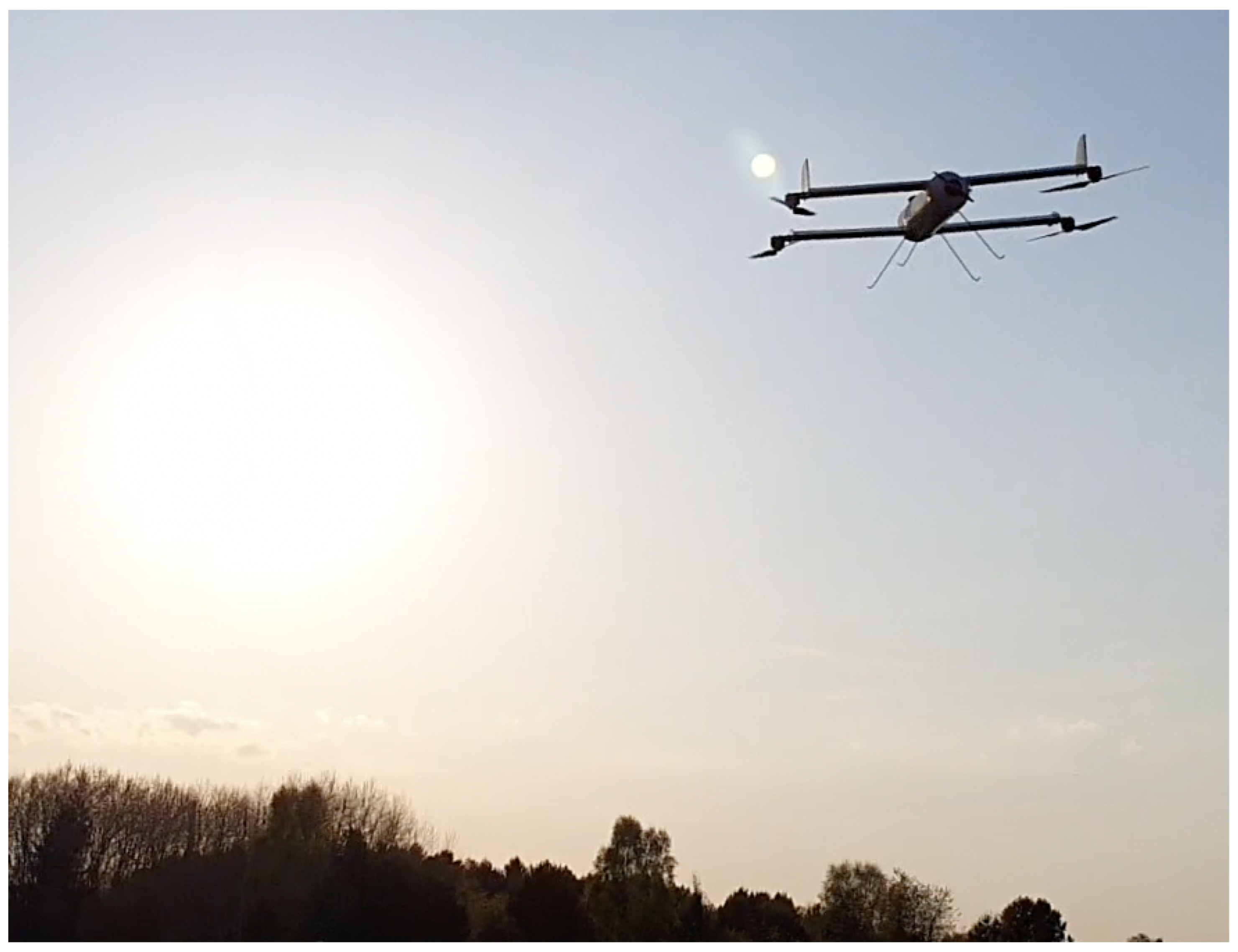
The in-flight experiments (
Figure 25) were divided into two stages:
VTOL (quadcopter) mode flights and onboard systems check: stabilize mode, hover, GPS position hold mode, GPS return-to-land mode, smooth auto-landing using the laser rangefinder, and low-speed forward flight with the pusher motor.
In-flight mode transition test and plane mode performance analysis.
The first stage of test flights went without any serious issues. We discovered some instability in the onboard barometer readings—most likely due to pressure changes inside the fuselage caused by wind gusts. The barometer is not crucial for the flights; GPS provides a redundant coarse altitude value. The laser rangefinder provides precise and accurate low altitude readings necessary for the auto-landing feature. The drone behaves correctly in hover, responds sharply to pilot commands, and proved to be quite resistant to wind gusts. Crosswind gusts induced some mild roll oscillations due to the presence of wing surfaces. Low-speed horizontal flight using the pusher motor did not reveal any stability issues. The drone maintained its attitude correctly.
The second stage of test flights revealed a few issues, some severe enough to lead to a few crash landings eventually.
Figure 26 shows a telemetry log from an experimental flight when at about the 120th second, the mode was changed from quadcopter to Elka1Q. The drone dived rapidly. Immediate manual intervention (switching back to the quadcopter mode) rescued the drone while it still stayed airborne. The situation repeated in a few other attempts, sometimes flipping the drone by 180° (a half-loop). We concluded that the drone could have misplaced its CG. The eCalc CG tool states that the calculation results should be carefully examined in test flights due to numerous limitations, including, but not limited to “fat” fuselage effects and aerodynamic performance analysis. The overall static and dynamic plane stability will also depend on the control surface effectiveness and the attitude controller robustness. Eventually, we fixed that issue by moving the CG by ca. 10 mm forward.
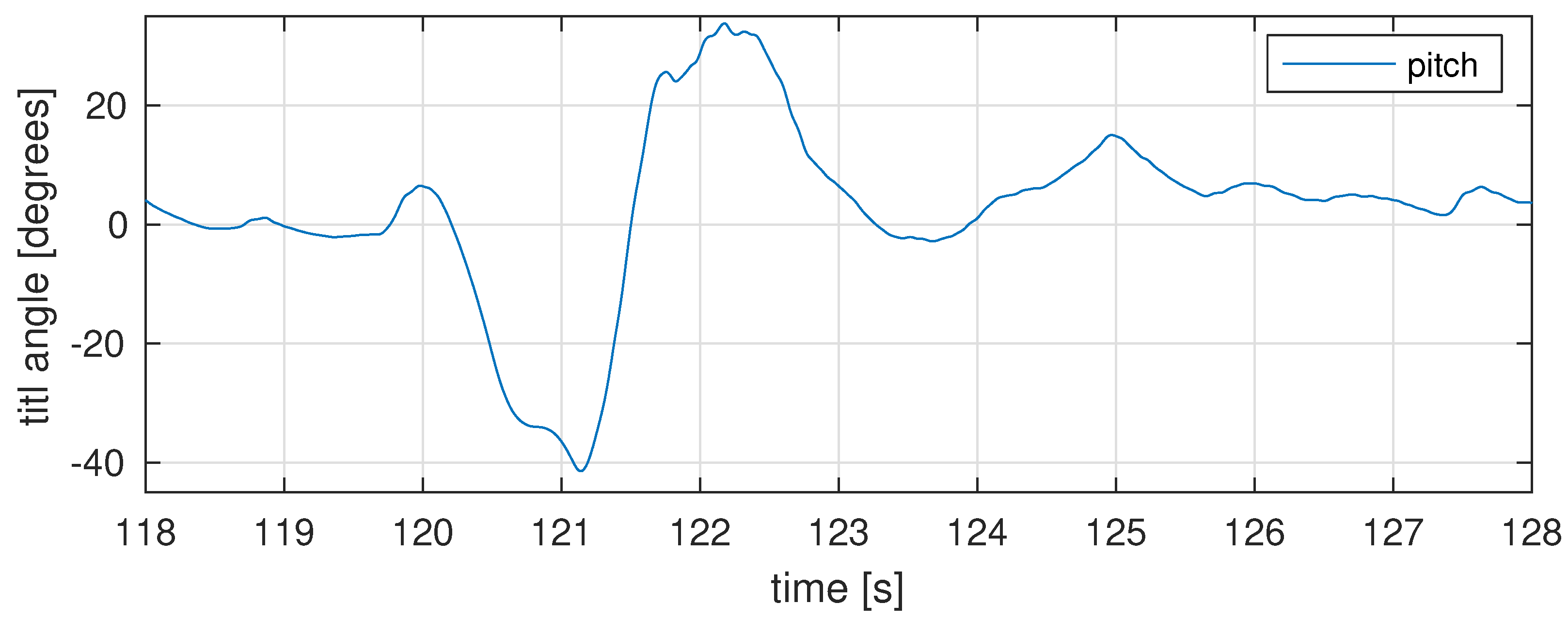
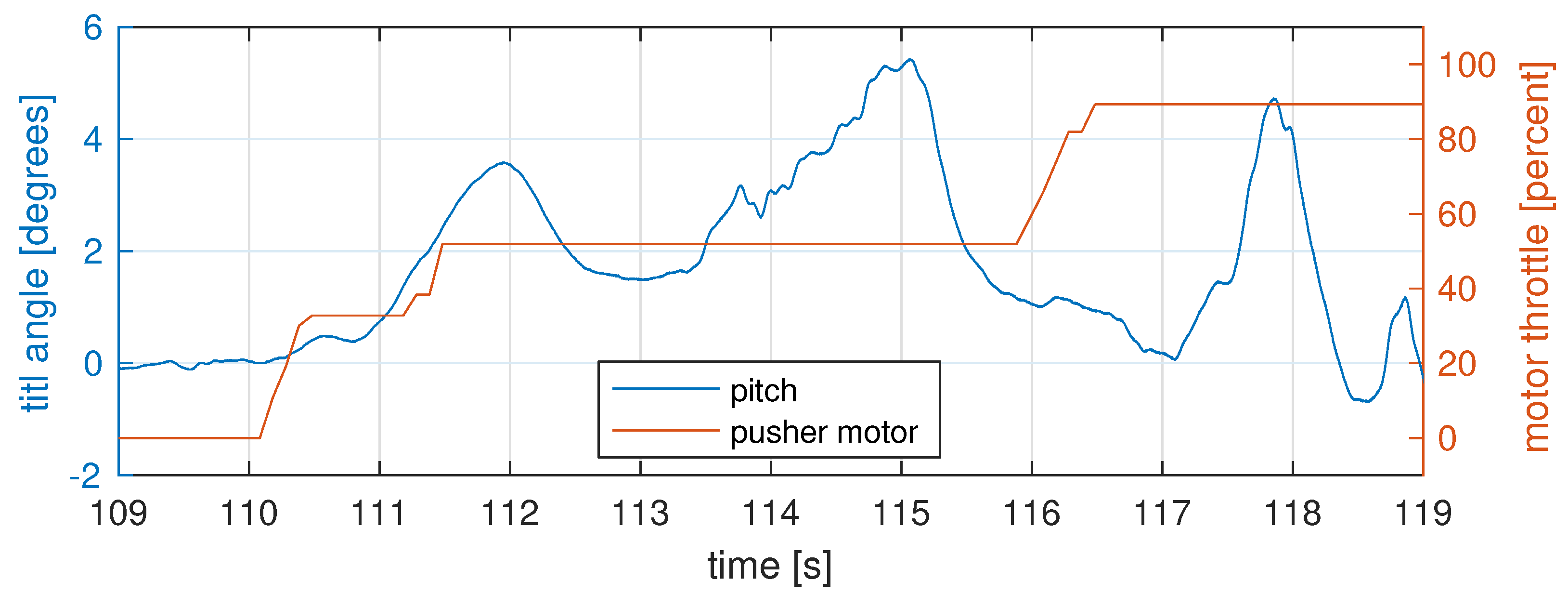
Further flights showed that the pitch controller still is not always stable enough—in some flights, after accelerating the drone and switching it to plane mode, the drone became extremely pitch-unstable (
Figure 27). Fast horizontal flights in quadcopter mode (using the pusher motor to accelerate) also revealed some pitch instability (oscillations in
Figure 28 starting from the 111th second).
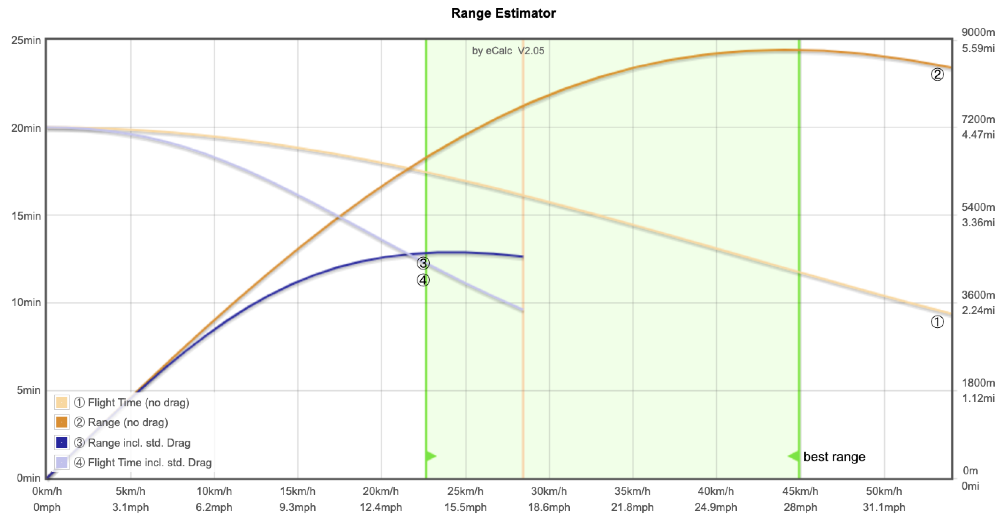
Figure 29 presents power usage in quadcopter mode (<55 s), during the transition phase (55–65 s; the drone accelerates with pusher motor; quadcopter motors still work) and plane mode (>65 s; only pusher motor works; other motors were shut down). It is worth mentioning that the electric power needed during the hover phase and the level flight in plane mode is nearly identical (total current drawn from the battery was ca. 20 A). The key difference is related to the horizontal speed of the drone in plane mode (above 100 km/h), while any non-zero forward flight speed in quadcopter mode requires more power than in hover. The eCalc predicts (see
Figure 5 and
Figure 6) that in quadcopter mode, the practical maximum speed will be less than 35 km/h at maximum main motor power (current readings over 60 A!). That proves the plane mode’s efficiency—the drone can fly 3× faster while consuming 3× less electric energy!
Due to safety reasons, we performed the top speed test only partially.
Figure 30 shows that we measured ca. 105 km/h top speed in a level flight.
4. Discussion
The mechanical construction of the drone proved to be successful. It was lightweight and highly robust and rigid. The only disadvantage of the construction was related to the complicated maintenance of internal components.
The complete electronic components used in the drone worked with no issues. Especially, the Kakute F7 AIO Flight Controller was a good choice—it was tiny, yet highly reliable and robust.
Thanks to excellent documentation and community support, working with the ArduCopter software stack was a pleasure. Implementing new flight modes was eventually relatively easy.
The VTOL test flights revealed no issues, which means the optimized quadcopter electric propulsion provides significant lift force and still guarantees good manoeuvrability. The motors and propellers were designed to carry 300 g of payload, while the drone could easily lift an additional 1500 g of payload—or hover longer with a nominal payload.
The pusher motor also performed well—the acceleration was instant, and the high pitch-speed of the propeller surely could accelerate the drone to an even higher top speed than the measured 105 km/h.
Building wings around the quadcopter motor holders also proved a good idea. However, the aerodynamic configuration of a tandem wing turned out to be surprising and challenging. The first serious problem was related to the correct CG localization. The calculated value seemed to be placed too far aft. That mistake caused one of the crash landings.
Another issue was related to pitch instability. It was caused (most likely) by too small (and thus inefficient) elevons. However, the findings based on telemetry logs were sometimes inconclusive in this matter.
The drone finally proved it could fly fast using its tandem-wing and the pusher motor only. Due to airfield restrictions, we could not perform a full top speed test and long-endurance flights. Nevertheless, we measured the electric power usage in both flight phases. Based on that, we could estimate the drone range.
5. Conclusions
This research aimed to design, build, and test a unique UAV in flight: optimized for efficient hover, but able to fly in long-range missions. We chose a tandem-wing configuration because it is the most compact variant of a VTOL drone compared to a fixed-wing one. We proved in our test flights that the drone could fly very fast (in plane mode) using the same electric power as in hover (in quadcopter mode). That feature lets it cover a longer distance than a typical multi-rotor could do. Additionally, we could optimize motors and propellers for a single purpose, unlike motor-tilting constructions. The tandem-wing configuration is also significantly smaller and lighter than a typical quadplane of the same wing area.
Eventually, we designed, calculated, simulated, built, and tested the Elka1Q drone in static tests and in flight. We also identified a model of the drone dynamics to improve its attitude controller implementation and experiment with custom-made MPC controllers.
The flights proved the wings almost do not affect the drone behaviour in hover and VTOL manoeuvres.
Fast horizontal flights using the pusher motor and transitioning to plane mode proved the drone could cover a significant distance in a short amount of time, i.e., it can operate in long-range missions. We measured the electric power usage and concluded that the prototype drone offers a 5× more extended range than a typical VTOL-only UAV (e.g., a multirotor). The compact mechanical construction of the tandem-wing and the fuselage proved to be extremely robust—it survived some crash landings with very little damage, having a take-off weight of ca. 2900 g!
The most significant disadvantages of the Elka1Q drone are related to its pitch stability issues. Some were caused by a misplaced CG, some plausibly by inefficient elevons, but some remain unexplained. We suggest examining the pitch controller in a wide range of conditions and possibly tuning it further.
Future research could optimize the wings and measure all the physical limits of such a drone, such as the actual top speed and range with a selected mission scenario.
Author Contributions
Conceptualization, M.O. and M.Ł.; methodology, M.O. and M.Ł.; software, M.O.; validation, M.O.; formal analysis, M.O. and M.Ł.; investigation, M.O.; resources, M.O.; data curation, M.O.; writing—original draft preparation, M.O.; writing—review and editing, M.O. and M.Ł.; visualization, M.O.; supervision, M.Ł.; project administration, M.Ł. All authors have read and agreed to the published version of the manuscript.
Funding
This research received no external funding.
Institutional Review Board Statement
Not applicable.
Informed Consent Statement
Not applicable.
Data Availability Statement
Not applicable.
Conflicts of Interest
The authors declare no conflict of interest.
Abbreviations
The following abbreviations are used in this manuscript:
| UAV | Unmanned Aerial Vehicle |
| SAR | Search-And-Rescue |
| PID | Proportional–Integral–Derivative |
| IMU | Inertial Measurement Unit |
| MPC | Model Predictive Controller |
| GPC | Generalized Predictive Controller |
| FC | Flight Controller |
| CG | Centre of Gravity |
| AoA | Angle of Attack |
| ESC | Electronic Speed Controller |
References
- Razi, P.; Sumantyo, J.T.S.; Perissin, D.; Kuze, H.; Chua, M.Y.; Panggabean, G.F. 3D Land Mapping and Land Deformation Monitoring Using Persistent Scatterer Interferometry (PSI) ALOS PALSAR: Validated by Geodetic GPS and UAV. IEEE Access 2018, 6, 12395–12404. [Google Scholar] [CrossRef]
- Máthé, K.; Buşoniu, L. Vision and control for UAVs: A survey of general methods and of inexpensive platforms for infrastructure inspection. Sensors 2015, 15, 14887–14916. [Google Scholar] [CrossRef] [PubMed] [Green Version]
- Heutger, M.; Kückelhaus, M. Unmanned Aerial Vehicles in Logistics a DHL Perspective on Implications and Use Cases for the Logistics Industry; DHL Customer Solutions & Innovation: Troisdorf, Germany, 2014. [Google Scholar]
- Waharte, S.; Trigoni, N. Supporting search and rescue operations with UAVs. In Proceedings of the 2010 International Conference on Emerging Security Technologies, Canterbury, UK, 6–7 September 2010; pp. 142–147. [Google Scholar]
- Aljehani, M.; Inoue, M. Performance Evaluation of Multi-UAV System in Post-Disaster Application: Validated by HITL Simulator. IEEE Access 2019, 7, 64386–64400. [Google Scholar] [CrossRef]
- Scott, J.E.; Scott, C.H. Drone Delivery Models for Medical Emergencies. In Delivering Superior Health and Wellness Management with IoT and Analytics; Springer International Publishing: Cham, Switzerland, 2020; pp. 69–85. [Google Scholar]
- Alicandro, M.; Dominici, D.; Massimini, V. Surveys with UAV photogrammetry: Case studies in l’Aquila during the post-earthquake scenario. In Proceedings of the EGU General Assembly Conference Abstracts, Vienna, Austria, 12–17 April 2015; p. 14987. [Google Scholar]
- Perez-Grau, F.; Ragel, R.; Caballero, F.; Viguria, A.; Ollero, A. Semi-autonomous teleoperation of UAVs in search and rescue scenarios. In Proceedings of the 2017 International Conference on Unmanned Aircraft Systems (ICUAS), Miami, FL, USA, 13–16 June 2017; pp. 1066–1074. [Google Scholar] [CrossRef]
- Chung, P.H.; Ma, D.M.; Shiau, J.K. Design, manufacturing, and flight testing of an experimental flying wing UAV. Appl. Sci. 2019, 9, 3043. [Google Scholar] [CrossRef] [Green Version]
- Jensen, A.M.; Baumann, M.; Chen, Y. Low-cost multispectral aerial imaging using autonomous runway-free small flying wing vehicles. In Proceedings of the IGARSS 2008-2008 IEEE International Geoscience and Remote Sensing Symposium, Boston, MA, USA, 8–11 July 2008; Volume 5, p. V-506. [Google Scholar]
- Austin, R. Unmanned Aircraft Systems: UAVS Design, Development and Deployment; John Wiley & Sons: Hoboken, NJ, USA, 2011. [Google Scholar]
- Valavanis, K.P.; Vachtsevanos, G.J. Handbook of Unmanned Aerial Vehicles; Springer: Dordrecht, The Netherlands, 2015; Volume 1. [Google Scholar]
- Cai, G.; Chen, B.M.; Peng, K.; Dong, M.; Lee, T.H. Modeling and Control System Design for a UAV Helicopter. In Proceedings of the 2006 14th Mediterranean Conference on Control and Automation, Ancona, Italy, 28–30 June 2006; pp. 1–6. [Google Scholar] [CrossRef]
- Peng, K.; Cai, G.; Chen, B.M.; Dong, M.; Lum, K.Y.; Lee, T.H. Design and implementation of an autonomous flight control law for a UAV helicopter. Automatica 2009, 45, 2333–2338. [Google Scholar] [CrossRef]
- Mehmood, H.; Nakamura, T.; Johnson, E.N. A maneuverability analysis of a novel hexarotor UAV concept. In Proceedings of the 2016 International Conference on Unmanned Aircraft Systems (ICUAS), Arlington, VA, USA, 7–10 June 2016; pp. 437–446. [Google Scholar]
- Jannoura, R.; Brinkmann, K.; Uteau, D.; Bruns, C.; Joergensen, R.G. Monitoring of crop biomass using true colour aerial photographs taken from a remote controlled hexacopter. Biosyst. Eng. 2015, 129, 341–351. [Google Scholar] [CrossRef]
- Mahony, R.; Kumar, V.; Corke, P. Multirotor aerial vehicles: Modeling, estimation, and control of quadrotor. IEEE Robot. Autom. Mag. 2012, 19, 20–32. [Google Scholar] [CrossRef]
- Yang, H.; Lee, Y.; Jeon, S.Y.; Lee, D. Multi-rotor drone tutorial: Systems, mechanics, control and state estimation. Intell. Serv. Robot. 2017, 10, 79–93. [Google Scholar] [CrossRef]
- Eraslan, Y.; Özen, E.; Oktay, T. The Effect of Change in Angle Between Rotor Arms on Trajectory Tracking Quality of a PID Controlled Quadcopter. In Proceedings of the EJONS 10th International Conference on Mathematics, Engineering, Natural Medical Sciences, Batumi, Georgia, 15–17 May 2020. [Google Scholar]
- Koehl, A.; Rafaralahy, H.; Boutayeb, M.; Martinez, B. Aerodynamic modelling and experimental identification of a coaxial-rotor UAV. J. Intell. Robot. Syst. 2012, 68, 53–68. [Google Scholar] [CrossRef]
- Dzul, A.; Hamel, T.; Lozano, R. Modeling and nonlinear control for a coaxial helicopter. In Proceedings of the IEEE International Conference on Systems, Man and Cybernetics, Toronto, ON, Canada, 9–12 October 2002; Volume 6, p. 6. [Google Scholar]
- Govdeli, Y.; Muzaffar, S.M.B.; Raj, R.; Elhadidi, B.; Kayacan, E. Unsteady aerodynamic modeling and control of pusher and tilt-rotor quadplane configurations. Aerosp. Sci. Technol. 2019, 94, 105421. [Google Scholar] [CrossRef]
- Flores, G.R.; Escareño, J.; Lozano, R.; Salazar, S. Quad-tilting rotor convertible mav: Modeling and real-time hover flight control. J. Intell. Robot. Syst. 2012, 65, 457–471. [Google Scholar] [CrossRef] [Green Version]
- Muraoka, K.; Okada, N.; Kubo, D. Quad tilt wing vtol uav: Aerodynamic characteristics and prototype flight. In Proceedings of the AIAA Infotech@ Aerospace Conference and AIAA Unmanned...Unlimited Conference, Seattle, WA, USA, 6–9 April 2009; p. 1834. [Google Scholar]
- ATEA Concept Design. 2022. Available online: https://www.ascendance-ft.com/products/ (accessed on 10 May 2022).
- eMagic One—An eVTOL That Really Works. 2022. Available online: https://emagic-aircraft.com/ (accessed on 10 May 2022).
- Alba-Maestre, J.; Prud’homme van Reine, K.; Sinnige, T.; Castro, S.G. Preliminary propulsion and power system design of a tandem-wing long-range eVTOL aircraft. Appl. Sci. 2021, 11, 11083. [Google Scholar] [CrossRef]
- OKTAY, T.; Metin, U.; ÇELİK, H.; KONAR, M. PID based hierarchical autonomous system performance maximization of a hybrid unmanned aerial vehicle (HUAV). Anadolu Univ. J. Sci. Technol. A-Appl. Sci. Eng. 2017, 18, 554–562. [Google Scholar] [CrossRef]
- Çetinsoy, E.; Dikyar, S.; Hançer, C.; Oner, K.; Sirimoglu, E.; Unel, M.; Aksit, M. Design and construction of a novel quad tilt-wing UAV. Mechatronics 2012, 22, 723–745. [Google Scholar] [CrossRef]
- eCalc—Reliable Electric Drive Simulations. 2022. Available online: https://www.ecalc.ch/index.htm (accessed on 18 May 2022).
- MotoCalc Electric Flight Performance Prediction Software. 2022. Available online: http://www.motocalc.com/ (accessed on 18 May 2022).
- Oracover Film. 2022. Available online: https://www.oracover.de/film (accessed on 18 May 2022).
- Airfoil Plotter. 2022. Available online: http://airfoiltools.com/plotter/index?airfoil=p51dtip-il (accessed on 18 May 2022).
- Minardo, A. The Tandem Wing: Theory, Experiments and Practical Realisations; Politecnico DI Milano: Milan, Italy, 2014. [Google Scholar]
- Brinkworth, B. On the aerodynamics of the Miles Libellula tandem-wing aircraft concept, 1941–1947. J. Aeronaut. Hist. Pap. 2016, 2, 10–58. [Google Scholar]
- Tandemwings—Nest of Dragons. 2022. Available online: https://www.nestofdragons.net/weird-airplanes/tandemwings/ (accessed on 18 May 2022).
- The Quickie Q2. 2022. Available online: https://www.eaa.org/eaa/news-and-publications/eaa-news-and-aviation-news/bits-and-pieces-newsletter/03-14-2017-the-quickie-q2 (accessed on 18 May 2022).
- Linehan, D. Burt Rutan’s Race to Space: The Magician of Mojave and His Flying Innovations; Zenith Press: Singapore, 2011. [Google Scholar]
- Kakute F7 AIO V1.5—Holybro. 2022. Available online: http://www.holybro.com/product/kakute-f7-aio-v1-5/ (accessed on 18 May 2022).
- VL53L1X Time-of-Flight Distance Sensor Carrier with Voltage Regulator, 400cm Max. 2022. Available online: https://www.pololu.com/product/3415 (accessed on 18 May 2022).
- NXG-02, Raster Signal Connectors. 2022. Available online: https://ninigi.com/gb/en/product/ninigi/raster-signal-connectors/nxg-02/112945/ (accessed on 18 May 2022).
- Okulski, M.; Ławryńczuk, M. A Novel Neural Network Model Applied to Modeling of a Tandem-Wing Quadplane Drone. IEEE Access 2021, 9, 14159–14178. [Google Scholar] [CrossRef]
- ArduPilot. 2020. Available online: http://ardupilot.org/about/ (accessed on 1 September 2020).
- Tatjewski, P. Advanced Control of Industrial Processes: Structures and Algorithms; Springer Science & Business Media: Berlin/Heidelberg, Germany, 2007. [Google Scholar]
- Camacho, E.F.; Bordons, C. Model Predictive Control; Springer: London, UK, 1999. [Google Scholar]
- Okulski, M.; Ławryńczuk, M. How Much Energy Do We Need to Fly with Greater Agility? Energy Consumption and Performance of an Attitude Stabilization Controller in a Quadcopter Drone: A Modified MPC vs. PID. Energies 2022, 15, 1380. [Google Scholar] [CrossRef]
- Tabuada, P. Event-triggered real-time scheduling of stabilizing control tasks. IEEE Trans. Autom. Control 2007, 52, 1680–1685. [Google Scholar] [CrossRef] [Green Version]
- Yan, S.; Gu, Z.; Park, J.H.; Xie, X. Adaptive Memory-Event-Triggered Static Output Control of TS Fuzzy Wind Turbine Systems. IEEE Trans. Fuzzy Syst. 2021, 1–11. [Google Scholar] [CrossRef]
- Adding a New Flight Mode to Copter. 2021. Available online: https://ardupilot.org/dev/docs/apmcopter-adding-a-new-flight-mode.html (accessed on 11 November 2021).
- Okulski, M.; Ławryńczuk, M. Identification of Linear Models of a Tandem-Wing Quadplane Drone: Preliminary Results. In Advanced, Contemporary Control; Springer: Cham, Switzerland, 2020; pp. 219–228. [Google Scholar]
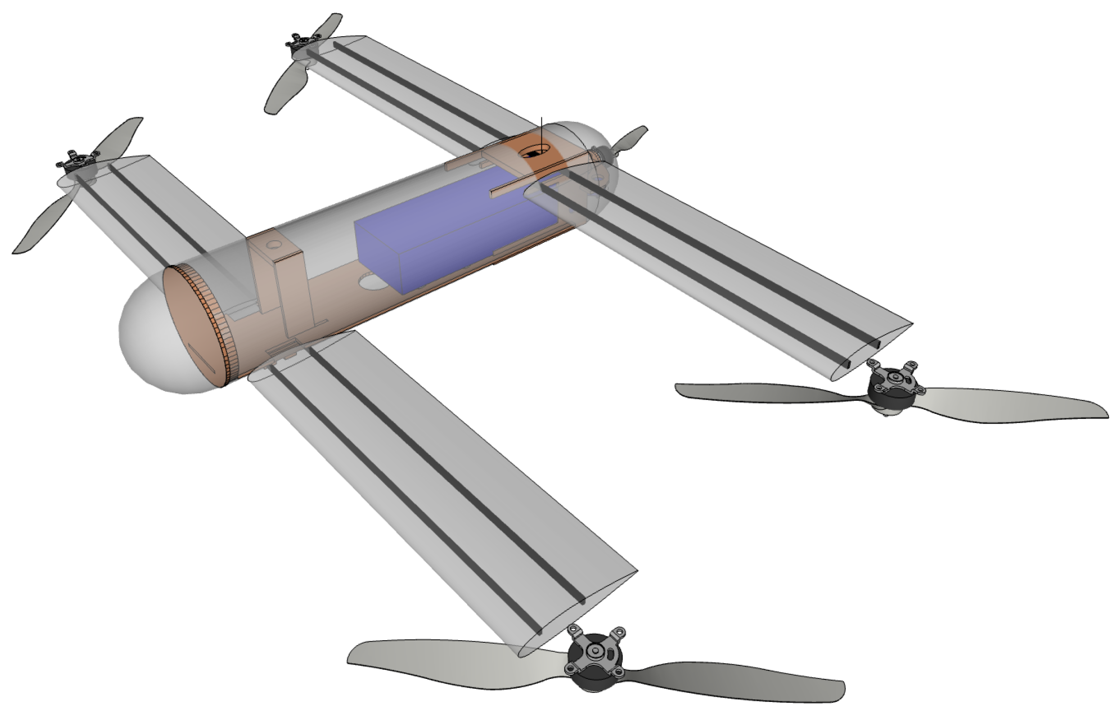
Figure 1.
The Elka1Q—an experimental tandem-wing quadplane UAV.
Figure 1.
The Elka1Q—an experimental tandem-wing quadplane UAV.
Figure 2.
The Elka1Q drone in one of its test flights.
Figure 2.
The Elka1Q drone in one of its test flights.
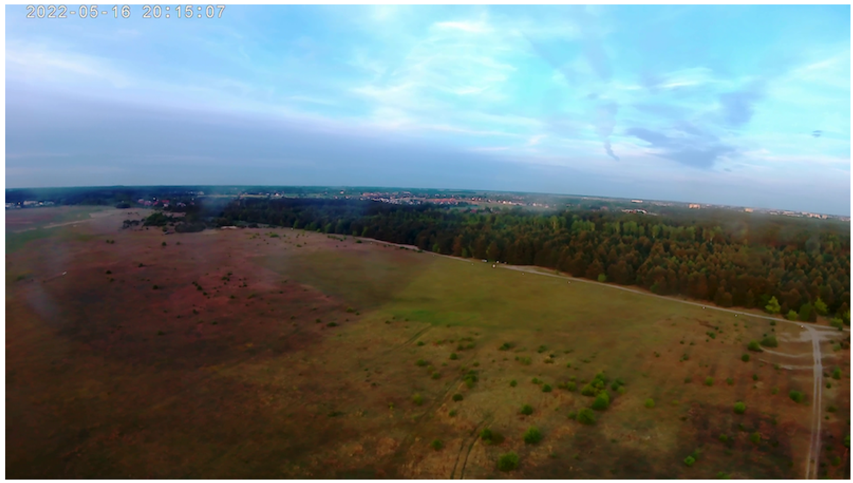
Figure 3.
View from the on-board video camera; altitude ca. 55 m above the airfield.
Figure 3.
View from the on-board video camera; altitude ca. 55 m above the airfield.
Figure 4.
An overview of popular UAV types.
Figure 4.
An overview of popular UAV types.
Figure 5.
The eCalc [
30] tool helped us find the best electric propulsion setup for the Elka1Q drone; disclaimer from eCalc:
* The manufacturer limitation is NOT monitored (relates to motor revolutions).
Figure 5.
The eCalc [
30] tool helped us find the best electric propulsion setup for the Elka1Q drone; disclaimer from eCalc:
* The manufacturer limitation is NOT monitored (relates to motor revolutions).
Figure 6.
The eCalc [
30] tool estimates the drone range and its general performance.
Figure 6.
The eCalc [
30] tool estimates the drone range and its general performance.
Figure 7.
The MotoCalc 8.09 [
31] workbench; the tool helped us estimate the drone performance in level flight (plane mode).
Figure 7.
The MotoCalc 8.09 [
31] workbench; the tool helped us estimate the drone performance in level flight (plane mode).
Figure 8.
An overview of the Elka1Q drone dimensions—top view.
Figure 8.
An overview of the Elka1Q drone dimensions—top view.
Figure 9.
An overview of the Elka1Q drone—side view.
Figure 9.
An overview of the Elka1Q drone—side view.
Figure 10.
The original airfoil for both drone wings; generated by Airfoil Plotter [
33].
Figure 10.
The original airfoil for both drone wings; generated by Airfoil Plotter [
33].
Figure 11.
An actual final wing airfoil—the original P-51D tip (BL215) airfoil is still visible underneath an extra top wing surface. The original wing was full-balsa construction, while the modification was based on a few balsa wood strips and a 1.5 mm-thick balsa wood covering.
Figure 11.
An actual final wing airfoil—the original P-51D tip (BL215) airfoil is still visible underneath an extra top wing surface. The original wing was full-balsa construction, while the modification was based on a few balsa wood strips and a 1.5 mm-thick balsa wood covering.
Figure 12.
Centre of Gravity (CG) calculated for the Elka1Q drone by the eCalc [
30] tool.
Figure 12.
Centre of Gravity (CG) calculated for the Elka1Q drone by the eCalc [
30] tool.
Figure 13.
The early Elka1Q fuselage mainly was made of carbon-fibre elements, but it was still not rigid enough.
Figure 13.
The early Elka1Q fuselage mainly was made of carbon-fibre elements, but it was still not rigid enough.
Figure 14.
Flight tests revealed that the early Elka1Q fuselage was twisting about the longitudinal axis (see the arrows).
Figure 14.
Flight tests revealed that the early Elka1Q fuselage was twisting about the longitudinal axis (see the arrows).
Figure 15.
The final design of Elka1Q fuselage—a PVC tube with internal plywood structure.
Figure 15.
The final design of Elka1Q fuselage—a PVC tube with internal plywood structure.
Figure 16.
The final design of the Elka1Q fuselage—the internal plywood structure.
Figure 16.
The final design of the Elka1Q fuselage—the internal plywood structure.
Figure 17.
The final design of Elka1Q fuselage—a PVC tube with internal plywood structure.
Figure 17.
The final design of Elka1Q fuselage—a PVC tube with internal plywood structure.
Figure 18.
A diagram explaining the wiring of all electronic components of the Elka1Q drone.
Figure 18.
A diagram explaining the wiring of all electronic components of the Elka1Q drone.
Figure 19.
A dedicated connector board improves the maintenance because the flight controller board is mounted deep inside the drone’s fuselage.
Figure 19.
A dedicated connector board improves the maintenance because the flight controller board is mounted deep inside the drone’s fuselage.
Figure 20.
Axes of rotation and control forces produced by the drone’s motors and elevons (at the rear wing).
Figure 20.
Axes of rotation and control forces produced by the drone’s motors and elevons (at the rear wing).
Figure 24.
The drone locked in a limited-freedom test harness.
Figure 24.
The drone locked in a limited-freedom test harness.
Figure 25.
Flight experiments.
Figure 25.
Flight experiments.
Figure 26.
Telemetry log from an in-flight experiment: a sudden pitch down (a dive) after the transition into plane mode because of misplaced CG—eventually rescued thanks to an immediate switch back to quadcopter mode.
Figure 26.
Telemetry log from an in-flight experiment: a sudden pitch down (a dive) after the transition into plane mode because of misplaced CG—eventually rescued thanks to an immediate switch back to quadcopter mode.
Figure 27.
Telemetry log from an in-flight experiment: pitch instability in plane mode flight.
Figure 27.
Telemetry log from an in-flight experiment: pitch instability in plane mode flight.
Figure 28.
Telemetry log from an in-flight experiment: a close-up on pitch instability observed in quadcopter mode when the pusher motor increased the drone’s speed in a horizontal flight.
Figure 28.
Telemetry log from an in-flight experiment: a close-up on pitch instability observed in quadcopter mode when the pusher motor increased the drone’s speed in a horizontal flight.
Figure 29.
Telemetry log from an in-flight experiment: battery current readings in quadcopter mode (up to 55th second), accelerating with pusher motor (up to 65th second) and quadcopter motors shut down when fully transitioned into plane flight mode.
Figure 29.
Telemetry log from an in-flight experiment: battery current readings in quadcopter mode (up to 55th second), accelerating with pusher motor (up to 65th second) and quadcopter motors shut down when fully transitioned into plane flight mode.
Figure 30.
Telemetry log from an in-flight experiment: top speed test in a horizontal flight in Elka1Q mode.
Figure 30.
Telemetry log from an in-flight experiment: top speed test in a horizontal flight in Elka1Q mode.
Table 1.
The final electric propulsion setup.
Table 1.
The final electric propulsion setup.
| Main Quadcopter Motors | 4× T-Motor MN3110 KV470 |
| Main Quadcopter Propellers | 4× T-Motor Carbon-Fibre (CF) |
| Main Quadcopter ESCs | 4× Hobbywing Micro 35A 3-6S BLHeli |
| Battery Type | Li-Ion, 18× Sony US18650VTC5 cell, custom-made battery pack |
| Battery Setup | 6S3P |
| Battery Capacity | 7500 mAh |
| Battery Voltage | 21.6 V nominal, 18–25.2 V full range |
| Battery Weight | 936 g |
| Pusher Motor | 1× T-Motor F60 PRO II KV1750 |
| Pusher Propeller | 1× APC-E (2-blade propeller) or 1× HQProp Ethix S5 (3-blade propeller) |
| Pusher Motor ESC | 1× Beatles 50 A |
| Total Drive Weight | ca. 1800 g |
Table 2.
Predicted performance of the electric drive setup; assumed 90% max allowed discharge and 300 g payload (e.g., a video camera with a companion single-board computer).
Table 2.
Predicted performance of the electric drive setup; assumed 90% max allowed discharge and 300 g payload (e.g., a video camera with a companion single-board computer).
| All-up Weight | 2900 g (2600 g + 300 g of payload) |
| Hover Flight Time | ca. 20.4 min |
| Top Speed (plane mode, using pusher motor) 1 | ca. 34–42 m/s (122–144 km/h) |
| Top Speed (quadcopter mode only) | ca. 8.9–12.5 m/s (32–45 km/h) |
| Max Range (VTOL, plane mode) 1 | ca. 25 km |
| Max Range (quadcopter mode only) | ca. 4.6 km |
| Stall Speed (plane mode) | ca. 11.1–13.9 m/s (40–50 km/h) |
| Publisher’s Note: MDPI stays neutral with regard to jurisdictional claims in published maps and institutional affiliations. |
© 2022 by the authors. Licensee MDPI, Basel, Switzerland. This article is an open access article distributed under the terms and conditions of the Creative Commons Attribution (CC BY) license (https://creativecommons.org/licenses/by/4.0/).


