Abstract
The paper presents some possible applications started from a six revolute joints (6R) overconstrained mechanism. The spatial devices obtained are based on the 6R Wohlhart symmetric mechanism in a special spatial position, with three non-adjacent joints constrained to remain in a fixed plane. This special spatial disposition allows us to obtain some reconfigurable/foldable devices, with an estimated application in the automotive industry field.
1. Introduction
An overconstrained mechanism is a special linkage with full range mobility. Even if the Grübler–Kutzbach mobility criterion gives a zero-mobility degree, or a rigid structure, some special parameters and geometric dimensions make these linkages mobile.
Six types of overconstrained mechanisms, such as the line-symmetric, the plane-symmetric, and the double collapsible octahedral linkages [1], as well as the line-symmetric, the plane-symmetric and the trihedral (rectangular) mechanism [2], are presented by Bricard in his papers.
In 1980, J.E. Baker analyzed these six mechanisms [3], obtaining the closure equations for these mechanisms, and in 1987 K. Wohlhart [4] generalized the concept of the Bricard rectangular mechanism, so that a new overconstrained mechanism is mentioned, the so-called threefold symmetric mechanism.
Many articles have presented these types of mechanisms, such as those with 4, 5 or 6 revolute joints (4R, 5R, 6R), from Bennett [5], Myard [6] or Goldberg [7] to Waldron [8], Mavroidis and Roth [9] or Dietmaier [10].
An industrial application for 6R closed-loop overconstrained mechanisms was presented by Schatz [11], and another possible application was first presented by Racila [12]. Starting from this estimated industrial application, many forms of other possible applications were developed by Zeng [13], combining overconstrained mechanisms with other serial, parallel and hybrid structures, and thus, many structural configurations were obtained.
Other applications of overconstrained mechanisms, foldable/deployable network based on Bennett linkage, were presented by Gan and Pellegrino [14], Baker [15] and Chen [16], as well as more recently by Ding [17] and Song [18].
This paper is focused on research results of another type of foldable/reconfigurable structure, starting from a 6R symmetric mechanism, in a particular spatial disposition and with good estimated application in the automotive industry. There are highlighted aspects related to the kinematic analysis, the configuration of the new rhombus mechanism and virtual prototyping.
2. Method for the Kinematic Analysis
2.1. Method for 6R Overconstrained Mechanism
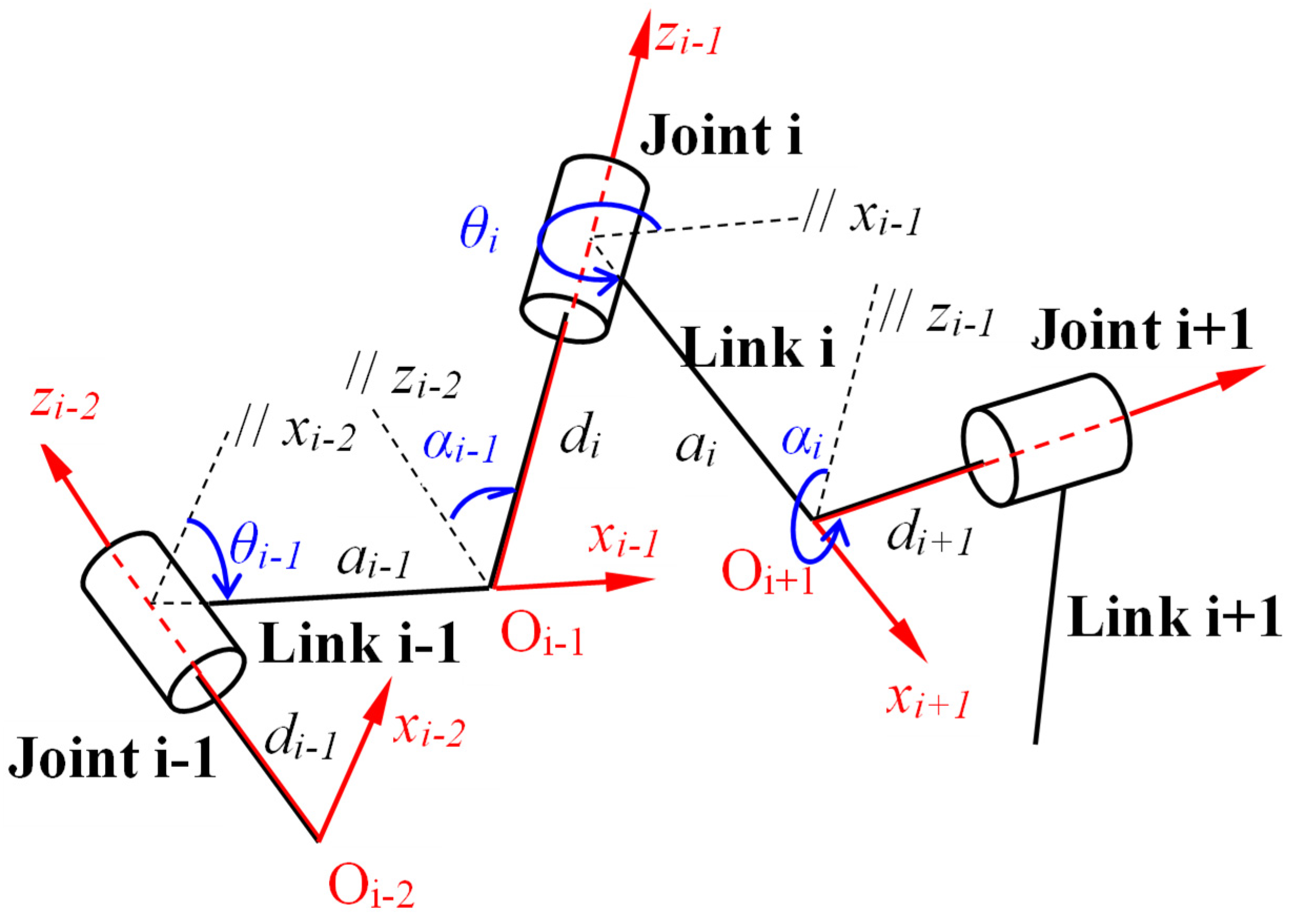
The classical position of the Wohlhart symmetric mechanism presents one fixed linkage, while the other five describe a spatial motion with a full mobility range. The mechanism can be analyzed with the help of Denavit–Hartenberg parameters [19]. Figure 1 shows three revolute joints and three links connecting the joints. For this linkage, the Denavit and Hartenberg notations are as follows: one kinematical variable θi—the rotation angle of the joint, and three geometrical parameters: ai the bar lengths, αi the twist angle between two successive joints (i) and (i + 1), and di the offset distance between two elements (i − 1) and (i).

Figure 1.
Denavit–Hartenberg parameters for three revolute joint linkage.
To obtain a closed loop, six joints will be linked, but special conditions must be set to the linkage in order to have a mobile mechanism. To obtain a closed loop mechanism, the condition is that the result of the six transfer matrices product must be equal to the unity matrix:
where the homogeneous form for the transfer matrix is:
In the particular case of a threefold-symmetric mechanism (Figure 2), six joints are linked with six links, with special geometrical conditions.
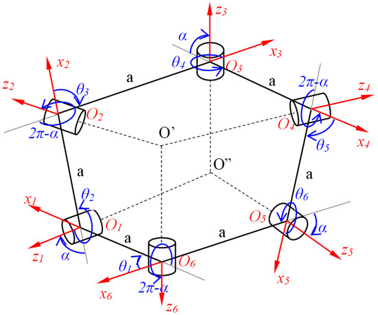
Figure 2.
Threefold symmetric mechanism.
The geometrical conditions for the case of a threefold-symmetric mechanism are:
The input and the output angles are:
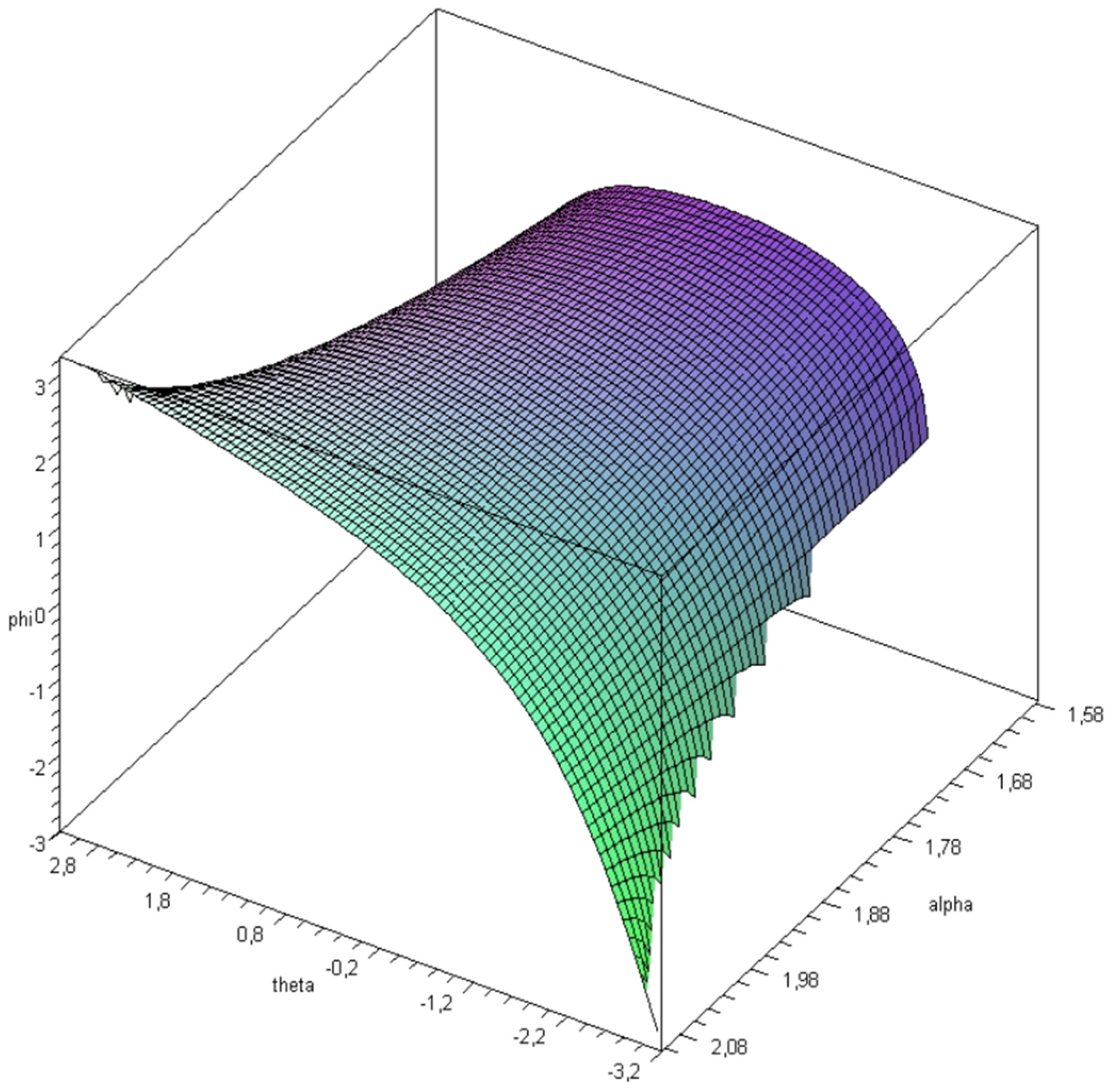
The input–output equation between the input angle θ and the output angle φ is [20]:
Figure 3 shows the output angle φ according to the input angle θ, when the twist angle α varies from π/2 to 2π/3. The link length is a = 170 mm.

Figure 3.
Output angle φ response surface.
2.2. Method for 6R Overconstrained Mechanism
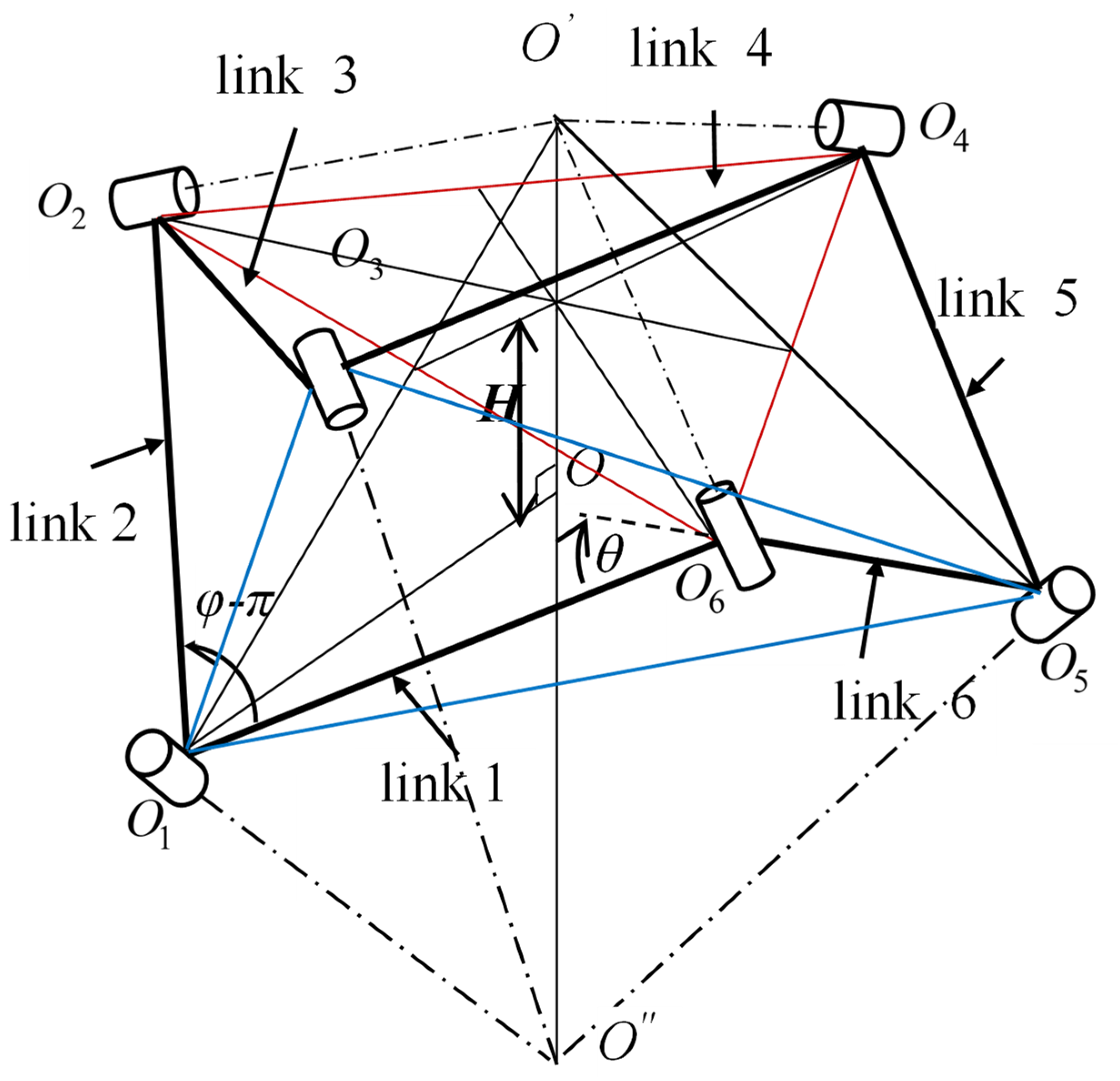
An estimated automotive industry application for these 6R overconstrained mechanisms would be obtained by setting the mechanism in a particular position.
Three non-adjacent joints are constrained to remain in a fixed horizontal plane (joints on the vertexes of an equilateral triangle), while the other three joints will be disposed in a parallel plane (joints on the vertexes of another equilateral triangle). Such a device will describe a parallel motion of three non-adjacent joints according to the other three non-adjacent joints as in Figure 4.
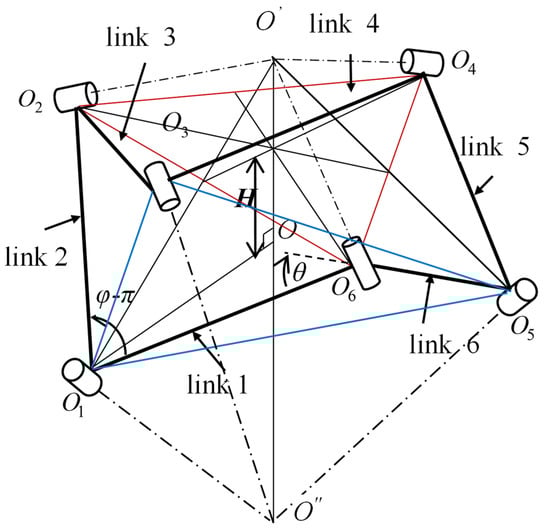
Figure 4.
6R overconstrained mechanism in the constrained position.
The distance H between the two planes can be evaluated according to the input–output angles [20]:
Starting from this constrained configuration, new possible applications can be obtained, imposing new movements for the actuated joints and combining many overconstrained mechanisms [21].
3. Results and Discussion
3.1. Mechansim Configuration
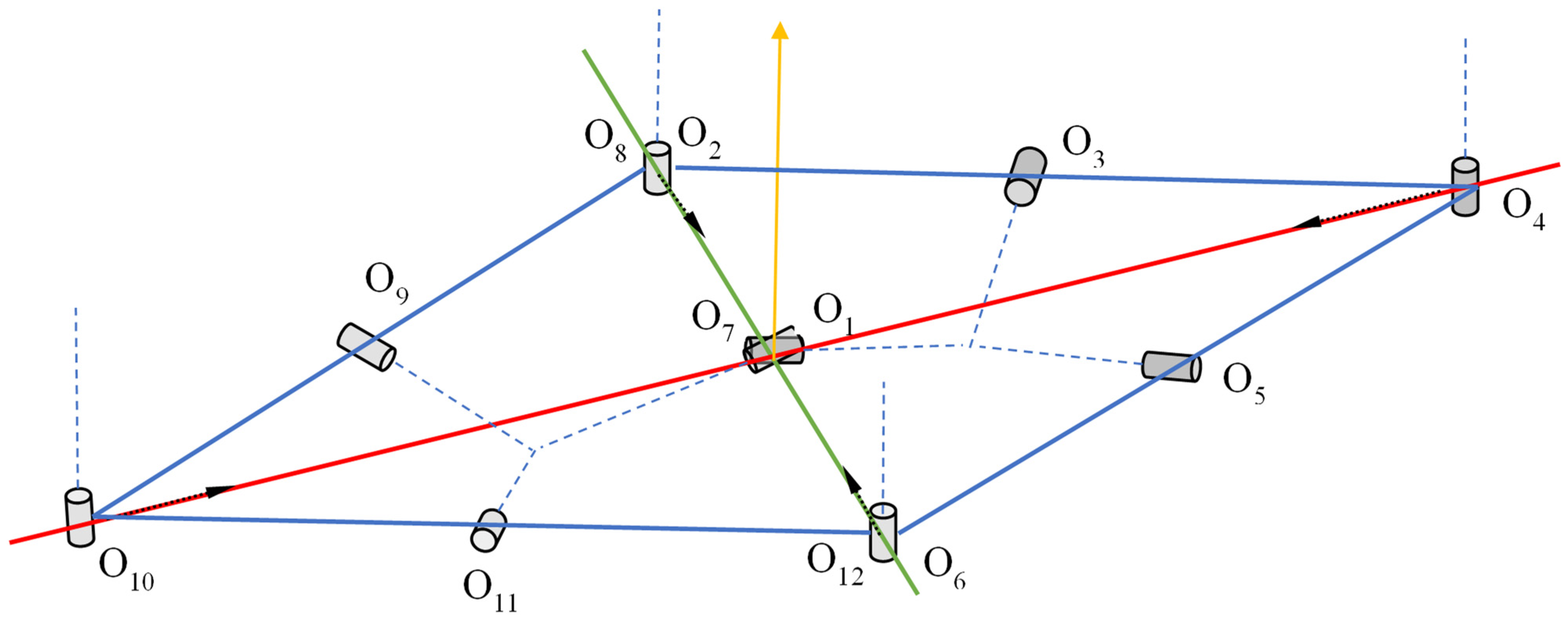
A new foldable device can be obtained by adding two 6R overconstrained mechanisms in a particular position, as shown in Figure 5. The joints O4 and O10 will have an imposed straight-line movement to the common line O4O10 (the red line, first diagonal of the initial rhomb O2O4O6O10), while joints O2, O6, O8 and O12 are constrained to have a linear movement on the second diagonal of the rhomb (the green line). Joints O2, O4, O6, O8, O10 and O12 will always remain in the horizontal plane of the movement. At the end of the movement, all 12 joints will be on the vertical line from the horizontal plane in the O1 point.
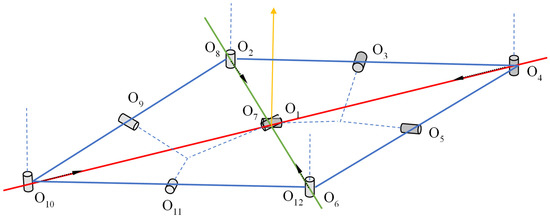
Figure 5.
Two 6R overconstrained mechanisms in a particular position.
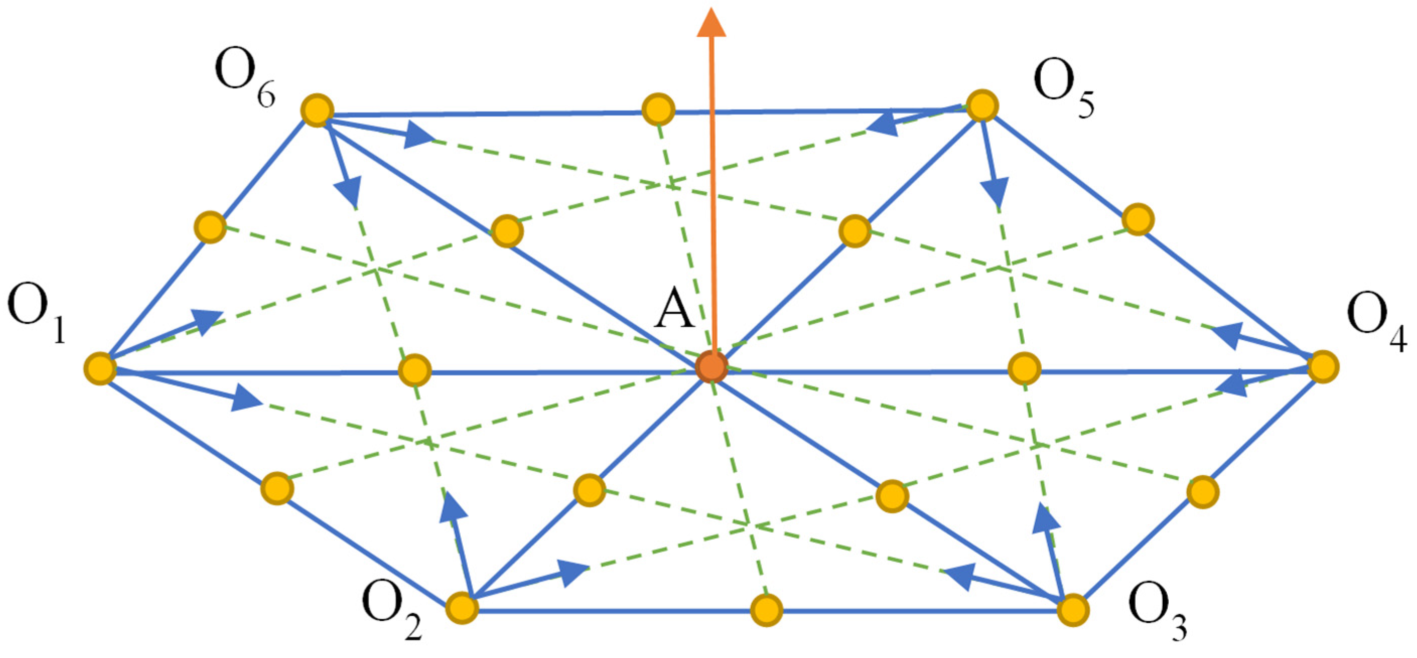
Another possibility is to put the mechanisms in a hexagon O1O2O3O4O5O6, with a fixed center A in the horizontal plane, summing a total of 36 joints, as can be seen in Figure 6 below. In point O1, there are two superposed joints, from a two side-by-side 6R mechanism, while in point A, there are six superposed joints, from all six mechanisms. Each nonadjacent joint, O1, O2, O3, O4, O5, and O6, will have an imposed straight in-plane linear movement, to the center of gravity of its own initial triangle (O1 and O2 to the gravity center of the O1O2A triangle, and so on). At the end of the movement, all 36 joints will be on the vertical line from the horizontal plane in A point.
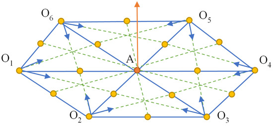
Figure 6.
Hexagon mechanism composed of multiple 6R assemblies and 36 joints.
In order to achieve the parallel translational 6R mechanism, it was necessary to have a multi-stage design and an optimization of the mechanism so that it could be collected as much as possible. In this respect, the connection between the joints in Figure 4, hereinafter referred to as connecting rods, has been divided into 2 components, rods, which allow the positioning of the ends of the connecting rod joints at different angles, 30, 60, 90, 120, etc. The design was carried out assisted by the Solidworks platform with the Solidworks Motion Analysis add-ins [22].
In order to be able to complete the mechanism, a primary model was designed. At this initial stage of design, the final assembly of 6 connecting rods can be used to position the ends of the connecting rod joints at angles in increments of 60 degrees by connecting the rods with the help of a hexagon. At the same time, the final model cannot be raised very much because of interference between constructing components.
Following the analysis and printing of the components, as well as the testing of the mechanism, it was found that there is a need for a much more detailed model of the rod, allowing the mechanism to be tightened as much as possible, at the same time allowing a multitude of configurations based on the angle between the ends of the connecting joints.
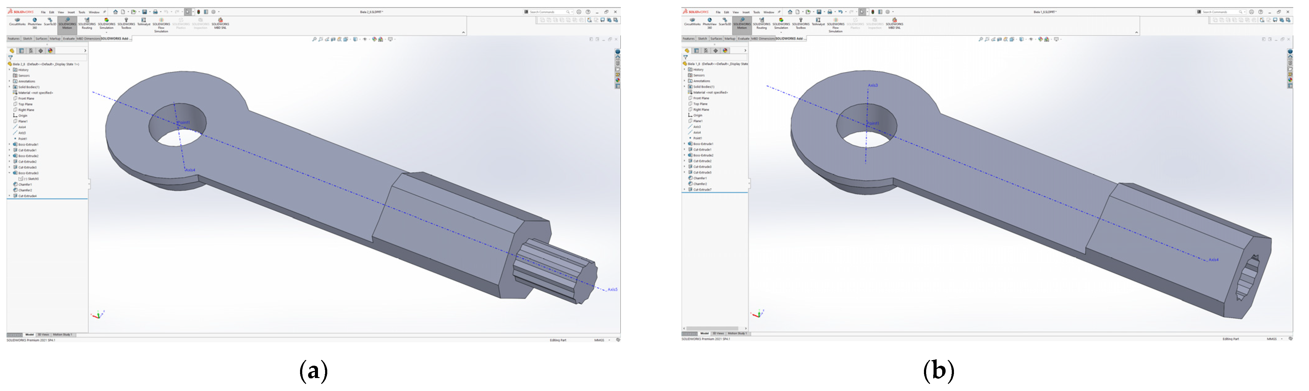
The final solution of the connecting rod resulted in the redesigning of another variant. In order to allow adjustments of the angles to be as smooth as possible, the connection of the two rods was made through a triangular groove, as can be seen in Figure 7.
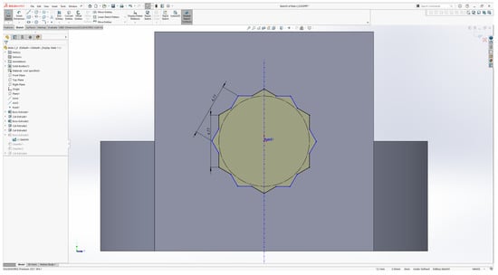
Figure 7.
Connecting the rods through a triangular groove.
Apart from the connection of the two rods, the actual design has also been modified to allow tightening at angles as close to ideal as possible; at the same time, the model can now be approved for the virtual prototyping process. Figure 8 shows the final solution used in the construction of the rods.
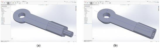
Figure 8.
The final construction version of the rods: (a) Male rod connection; (b) Female rod connections.
3.2. Customized Rhombus Mechanism
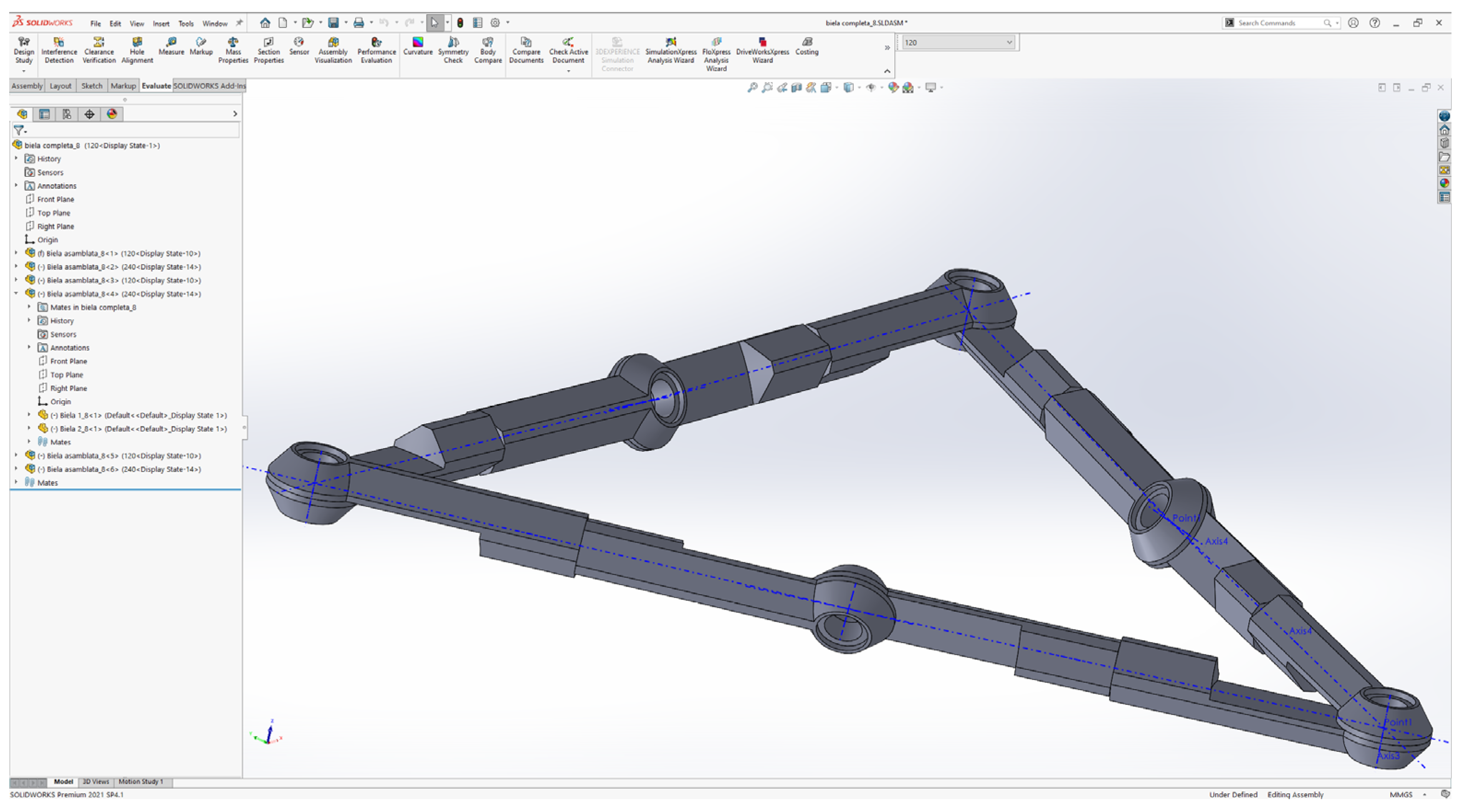
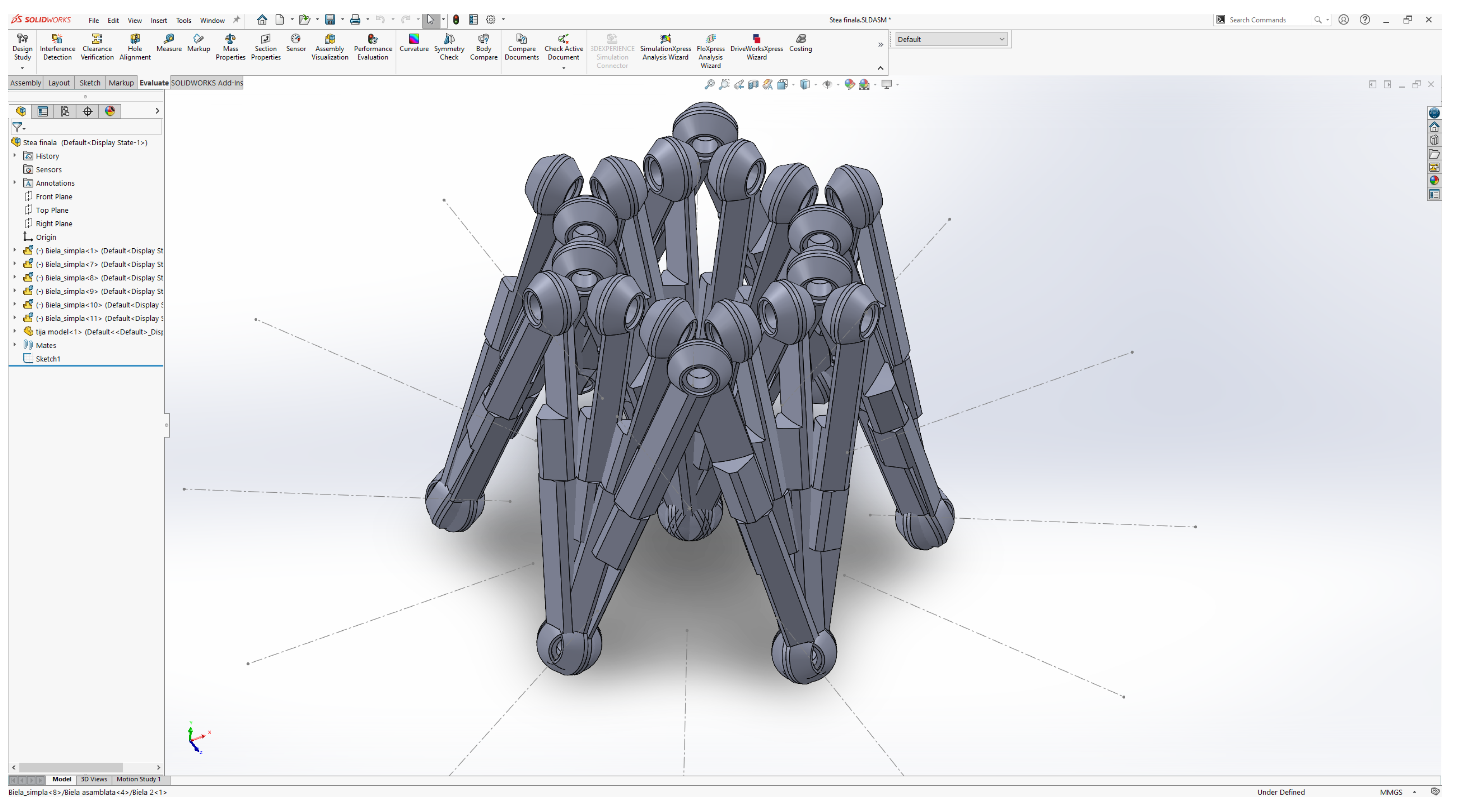
A very useful variant of the mechanism is given by the use of two 6R mechanisms, a mechanism that can be seen in Figure 9, and their constraints so that tightening is carried out at the central point. At the same time, each rod is connected at an angle of 120 degrees so that the rising is maximum.
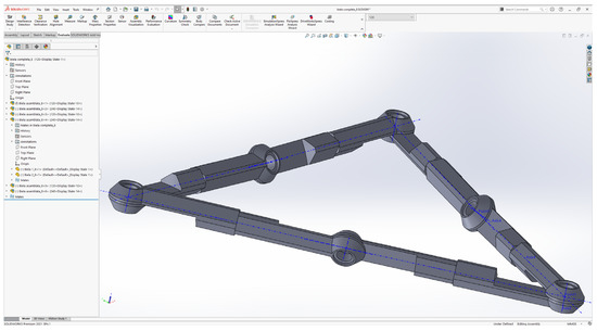
Figure 9.
Assembled 6R mechanism.
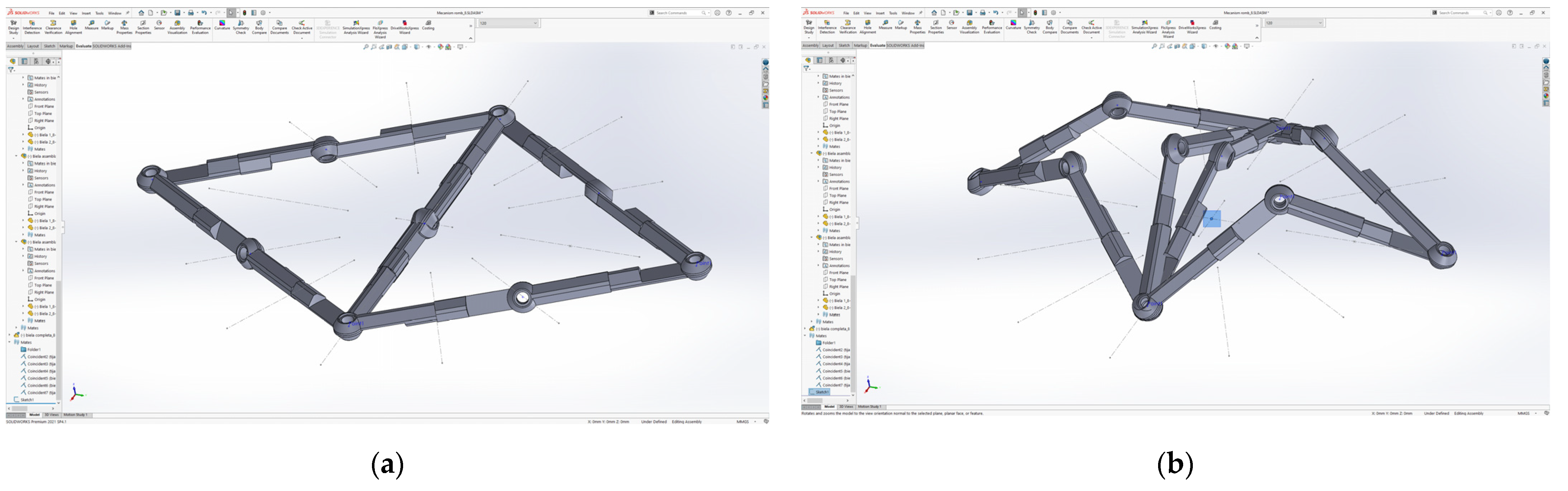
Although there are several variants of tightening the mechanism, the selected variant concentrates the assembly, consisting of the two 6R mechanisms, at a central point, as can be seen in Figure 10.
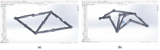
Figure 10.
3D design of the mechanism: (a) Unfolded mechanism; (b) Central tightening point (blue marking).
3.3. Customized Rhombus Mechanism
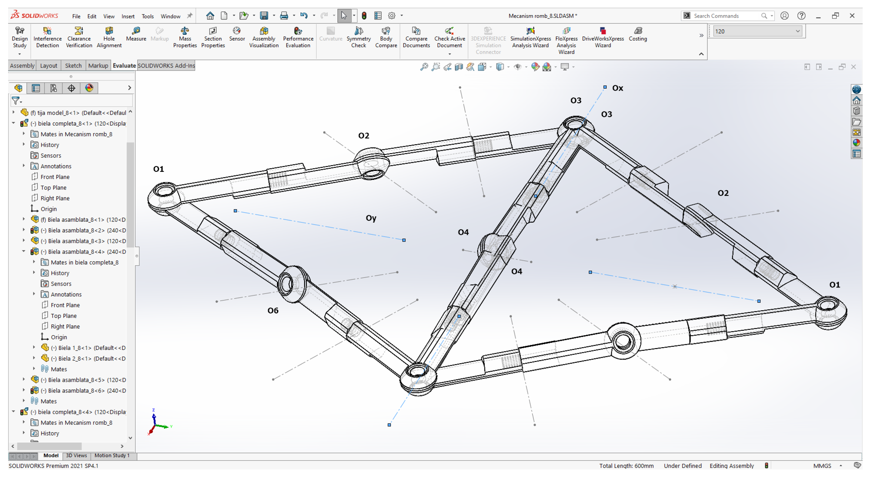
In order to tighten the mechanism in the central position, each 6R assembly was constrained in relation to a sketch in which construction geometries (axis of translation of the joints) were made at angles of 30 degrees between them. The configuration can be seen in Figure 11.
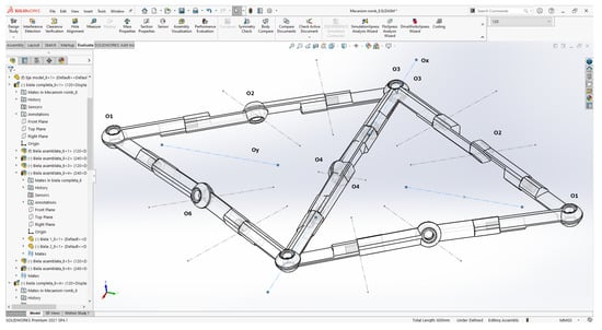
Figure 11.
Positioning of the joints within the rhombus mechanism.
In order to complete the rhombus mechanism, the sketch was blocked as a whole, and the joints of the mechanism were blocked, according to Figure 2 as follows:
- The free joints for both 6R mechanisms are O2, O4 and O6, according to Figure 2;
- The fixed plane joints for both 6R mechanisms are O1, O3 and O5, according to Figure 2;
- For tightening the rhombus type assembly, it is considered that the joints O3 and O5 move on the same axis (Ox);
- In order for both mechanisms to move at the same time, the O3 and O5 joints of each R6 mechanism are constrained at the same point, as can be seen in Figure 11;
- The tightening movement is given by the O1 joint after the Oy axis.
For the purpose of the tightening movement of the mechanism, the Motion Analysis add-ins from Solidworks were used. In this regard, for the movement of the mechanism, two linear motors were introduced on points O1 and O2, at the same time in the direction of the Oy axis, as shown in Figure 12.
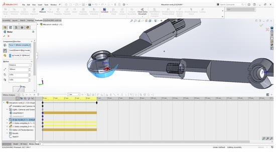
Figure 12.
Positioning of the linear motor on the O1 and O2 frames of the mechanism.
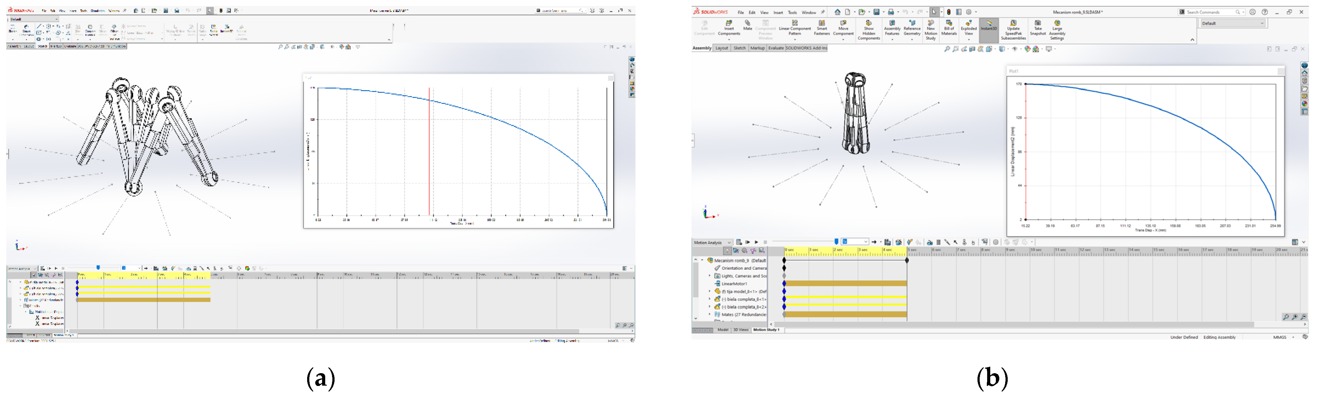
The movement is performed over a distance of 300 mm, a distance that does not allow a complete tightening, because from the virtual motion tests, we found that an ideal simulation, which perfectly tightens the mechanism, leads to errors in the integration type model area. Thus, following several successive tests, it has been established that the ideal distance for which the linear motor is active is 300 mm. The simulation duration was set to 5 s and results and movement can be seen in the Figure 13 and Figure 14.
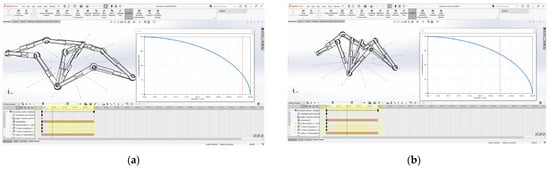
Figure 13.
Model of movement: (a) first position; (b) intermediate position.
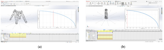
Figure 14.
Displacement model: (a) intermediate position; (b) final positions.
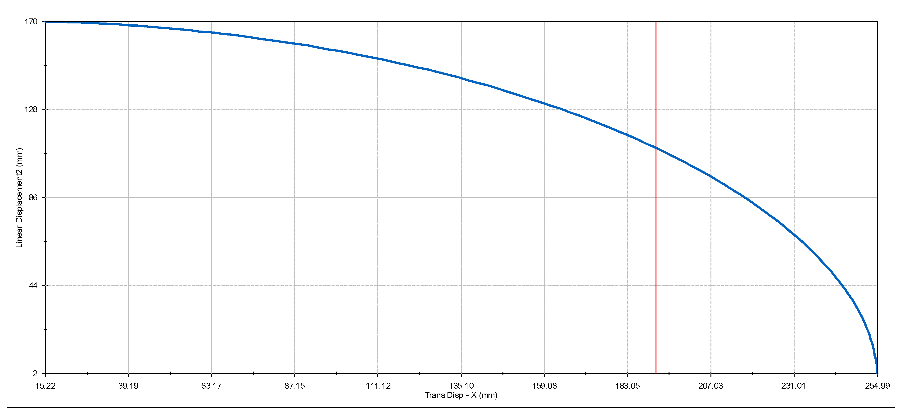
Following the simulation, one can see the graph of the movement of the joints, Figure 15, which rises on the Oz axis, in relation to the motorized joints moving on the Ox axis every second, as well as the position of the mechanism, Figure 13 and Figure 14. At the same time, the intermediate data for the movement of the mechanism can be seen in Table 1.
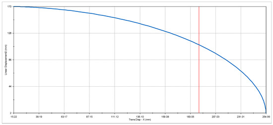
Figure 15.
Graph of the displacement of the joints on the Ox in relation to the joints on the Oz.

Table 1.
Intermediate points for joint movements.
3.4. Rhombus Mechanism Virtual Prototiping and 3D Printing
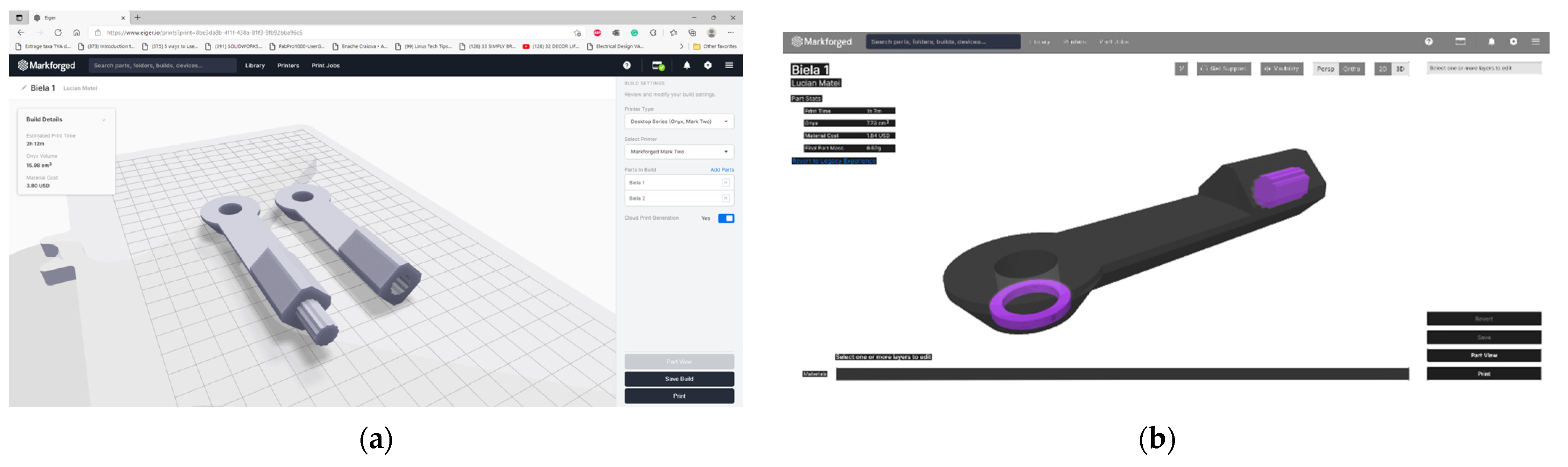
In order to see the exact movements of the 6R mechanism, as well as the tightening mode, it was necessary to use virtual prototyping methods. Following the evaluation of multiple 3D printing technologies, the only one that we consider to be the most useful in terms of costs, as well as the strength of printed elements was the FDM technology.
The printer on which the elements of the mechanism were printed is Markforged MarkTwo, and the material used is Onyx [23]. This material was chosen due to its very good mechanical characteristics, so the mechanism could be used with loads.
The processing of the parts for printing was carried out in the specific platform, Eiger, and the processing results can be seen in Figure 16.
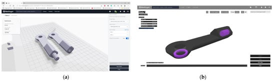
Figure 16.
Part processing stage: (a) Positioning on the table; (b) Internal view of the processed part.
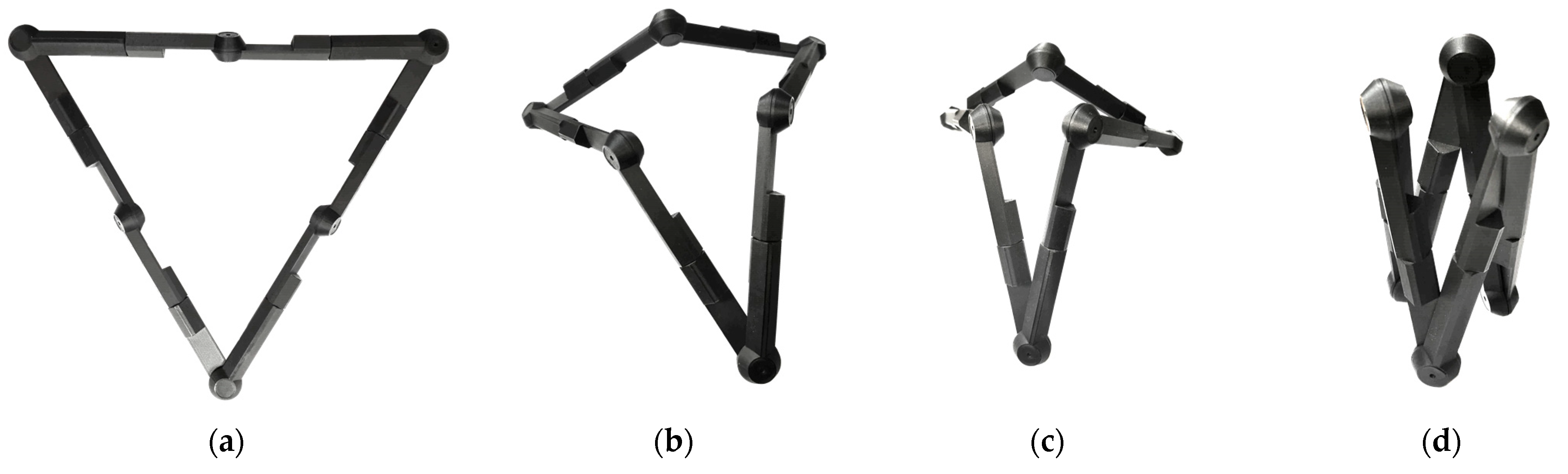
As can be seen from Figure 16, printing each connecting rod took about 2 h, and to complete the mechanism, it took 6 connecting rods. Following the completion of the prints and after the removal of the support, the rods of the rods of the rod were assembled. The assembly and positions of the printed mechanism can be seen in Figure 17.

Figure 17.
Assembled and functional mechanism: (a) Starting position; (b) Fist intermediate position; (c) Second intermediate position; (d) Final position.
4. Discussion
This paper presents aspects of research related to the possible applications and configurations of an overconstrained 6R mechanism.
The starting point of the paper is the presentation of a particular case of a threefold-symmetric mechanism (Figure 2). The positioning of the mechanism in a particular position, discussed in Section 2.2, created the starting premise of the rhombus design. By combining two 6R overconstrained mechanisms in a specific design, a novel foldable device can be created. The constraints of the mechanism and design are discussed in Section 3. The results discussed next focus on the 3D CAD model creation and 3D printing in order to create a first prototype. The final part of the paper uses virtual motion analysis software and the graph of the movement of the joints graph, which can be seen in Figure 15.
In regard to the novelty of the paper, the foldable mechanism is a novelty and was never presented. The research aim is to present and analyze the devices but at the same time to initiate the 3D printing and prototyping for the proposed design.
The 3D printed device, Figure 17, will be used to realize a first prototype of the rhombus mechanism.
A future paper will be dedicated to a mathematical and kinematical analyses, validated with the 3D printed prototype.
5. Conclusions
The paper presents the results of a new six revolute joints (6R) overconstrained closed-loop mechanism. The kinematic analysis and virtual prototyping presented in the paper sets the background of the reconfigurable/foldable overconstrained mechanism and estimates results for applications in mechatronic and automotive systems, such as:
- The mechanism can be used in elevators and jacks within the automotive industry because of good stability and fine tuning;
- Construction of hospital beds can be one of the largest benefits of this rhomb mechanism because it offers a complex movement type by using the translation motion of the joints. This translation of the joints defines very good precision; thus, the mechanism can be used in the construction of the fowler and the gatch. The integration of the mechanism will obtain better and more precise movement, thus creating enhanced comfort for different types of pathologies;
- The same precise movement can be used in the automotive industry by being integrated into the car seat to control the lumbar and headrest frames. The fine tune of the car seat can adjust the position of the driver with respect to the lines of physiological anatomy curvatures of the spine, avoiding, in this way, lordosis and kyphosis pathologies;
- This mechanism may also be used in the construction of wheelchairs for the fine control of lumbar and fowler positions;
- Another possible application could be in deployable devices or in various industrial areas, like entertainment/architecture area.
This type of overconstrained 6R mechanism can be assembled in several ways, and the case presented in this paper, two mechanisms constrained in a rhombus, has the advantage of better stability than the one in which the mechanism is singular.
Another example of a usage of the overconstrained 6R mechanisms is the assembly in hexagon and constraining the movement of active joints toward the center of the hexagon, as shown in Figure 6 and Figure 18.

Figure 18.
Hexagon intermediate position.
The advantage of the hexagon assembly lies in the larger support base, resulting in better stability, but it involves the use of 6 superconstrained 6R mechanisms for a more complicated drive of the final system.
There is also the possibility of overlapping several such devices, on several floors, the movement of exit from one floor (three non-adjacent joints from the lower floor) being the entrance movement to the next floor (three non-adjacent joints in the upper floor).
Author Contributions
Conceptualization, L.R. and L.M.; methodology, I.D. and L.R.; software L.M.; validation, L.R. and L.M.; formal analysis, M.R., I.D. and G.-M.B.M.; investigation, I.D. and M.R.; resources, L.M. and L.R.; writing—original draft preparation, L.R. and L.M.; writing—review and editing, L.M., L.R. and M.R.; supervision, I.D. and M.I. All authors have read and agreed to the published version of the manuscript.
Funding
This research received no external funding.
Institutional Review Board Statement
Not applicable.
Informed Consent Statement
Not applicable.
Data Availability Statement
Not applicable.
Acknowledgments
We especially thank CADWORKS International SRL for the support and help given in the elaboration of this work. https://www.cadworks.ro/ (accessed on 10 December 2021).
Conflicts of Interest
The authors declare no conflict of interest.
References
- Bricard, R. Mémoire sur la théorie de l’octaèdre articulé. J. Math. Pures Appl. 1897, 3, 113–148. [Google Scholar]
- Bricard, R. Leçons de Cinématique, Tome II—Cinématique Appliquée; Gauthier: Paris, France, 1927. [Google Scholar]
- Baker, J.E. An Analysis of the Bricard Linkages. Mech. Mach. Theory 1980, 15, 267–286. [Google Scholar] [CrossRef]
- Wohlhart, K. A New 6R Space Mechanism. In Proceedings of the Theory of Machines and Mechanisms: Proceedings of the 7th World Congress, Sevilla, Spain, 17–22 September 1987; pp. 193–198. [Google Scholar]
- Bennett, G.T. A new Mechanism. Engineering 1903, 76, 777–778. [Google Scholar]
- Myard, F.E. Chaîne fermée à cinq couples rotoïdes, déformable au premier degré de liberté. Comptes Rendus Hebd. Séances L’acad. Sci. 1931, 192, 1352–1354. [Google Scholar]
- Goldberg, M. New five–bar and six–bar linkages in three dimensions. Trans. ASME 1943, 65, 649–663. [Google Scholar]
- Waldron, K.J. Overconstrained Linkages. Environ. Plan. B 1979, 6, 393–402. [Google Scholar] [CrossRef]
- Mavroidis, C.; Roth, B. Analysis and Synthesis of Overconstrained Mechanisms. In Proceedings of the ASME 1994 International Computers in Engineering Conference and Exhibition and the ASME 1994 8th Annual Database Symposium, Minneapolis, MN, USA, 11–14 September 1994; pp. 115–133. [Google Scholar]
- Dietmaier, P. A new 6R space mechanism. In Proceedings of the 9th IFToMM World Congress, Milan, Italy, 29 August–5 September 1995; pp. 52–56. [Google Scholar]
- Schatz, P. Rhytmusforschung und Technik; Verlag Freies Geistesleben: Stuttgart, Germany, 1975; ISBN1 3772506496. ISBN2 9783772506499. [Google Scholar]
- Racila, L.; Dahan, M. Bricard Mechanism Used as Translator. In Proceedings of the 12th IFToMM World Congress, Besançon, France, 18–21 June 2007. [Google Scholar]
- Zeng, Q.; Ehmann, K.F. Ehmann, Design of parallel hybrid-loop manipulators with kinematotropic property and deployability. Mech. Mach. Theory 2014, 71, 1–26. [Google Scholar] [CrossRef]
- Gan, W.W.; Pellegrino, S. Closed-loop deployable structures. In Proceedings of the 44th AIAA/ASME/ASCE/AHS/ASC Structures, Structural Dynamics, and Materials Conference, Norfolk, VA, USA, 7 April–10 April 2003. [Google Scholar]
- Baker, J.E. Kinematic investigation of the deployable Bennett loop. J. Mech. Des. ASME 2007, 129, 602–610. [Google Scholar] [CrossRef]
- Chen, Y.; You, Z.; Tarnai, T. Threefold-symmetric Bricard Linkages for Deployable Structures. Int. J. Solids Struct. 2005, 42, 2287–2301. [Google Scholar] [CrossRef] [Green Version]
- Ding, W.; Qiang, R.; Yao, Y. Design and Locomotion Analysis of a Novel Deformable Mobile Robot with Two Spatial Reconfigurable platforms and Three Kinematic Chains. Proc. Inst. Mech. Eng. Part C J. Mech. Eng. Sci. 2016, 231, 1481–1499. [Google Scholar] [CrossRef]
- Song, X.; Deng, Z.; Guo, H.; Liu, R.; Li, L.; Liu, R. Networking of Bennett linkages and its application on deployable parabolic cylindrical antenna. Mech. Mach. Theory 2017, 109, 95–125. [Google Scholar] [CrossRef]
- Denavit, J.; Hartenberg, R.S. A Kinematic Notation for Lower–Pair Mechanism Based on Matrices. J. Appl. Mech. 1995, 22, 215–221. [Google Scholar] [CrossRef]
- Racila, L.; Dahan, M. Spatial properties of Wohlhart symmetric mechanism. Meccanica 2010, 45, 153–165. [Google Scholar] [CrossRef]
- Racila, L. One 6R Overconstrained Mechanism, Many Applications. In 11th IFToMM International symposium on Science of Mechanisms and Machine—SYROM 2013; Springer: Cham, Switzerland, 2014; pp. 81–90. ISBN 978-3-319-01844-7. [Google Scholar]
- Motion Analysis Overview. Available online: http://help.solidworks.com/2021/english/SolidWorks/motionstudies/c_Motion_Analysis.htm (accessed on 10 December 2021).
- Onyx. General Information. Available online: https://support.markforged.com/portal/s/article/Onyx (accessed on 10 December 2021).


Publisher’s Note: MDPI stays neutral with regard to jurisdictional claims in published maps and institutional affiliations. |
© 2021 by the authors. Licensee MDPI, Basel, Switzerland. This article is an open access article distributed under the terms and conditions of the Creative Commons Attribution (CC BY) license (https://creativecommons.org/licenses/by/4.0/).