Abstract
The aim of this study was to analyze the spinal stability and safety after posterior spinal fusion with various fixation segments and screw types in patients with an osteoporotic thoracolumbar burst fracture based on finite element analysis (FEA). To realize various osteoporotic vertebral fracture conditions on T12, seven cases of Young’s modulus, namely 0%, 1%, 5%, 10%, 25%, 50%, and 100% of the Young’s modulus, for vertebral bones under intact conditions were considered. Four types of fixation for thoracolumbar fracture on T12 (fixed with T11-L1, T10-T11-L1, T11-L1-L2, and T10-T11-L1-L2) were applied to the thoracolumbar fusion model. The following screw types were considered: pedicle screw (PS) and cortical screw (CS). Using FEA, four motions were performed on the fixed spine, and the stress applied to the screw, peri-implant bone (PIB), and intervertebral disc (IVD) and the range of motion (ROM) were calculated. The lowest ROM calculated corresponded to the T10-T11-L1-L2 model, while the closest to the intact situation was achieved in the T11-L1-L2 fixation model using PS. The lowest stress in the screw and PB was detected in the T10-T11-L1-L2 fixation model.
1. Introduction
Nearly 90% of spinal fractures occur in the thoracolumbar region, and burst fractures account for 10–20% of these types of injuries. These thoracolumbar burst fractures are the most common spinal fractures that are treated surgically [1,2]. Typically, a pedicle screw (PS) is used for spinal fixation, but the optimal fixation segment for each fracture site has not been established yet [3,4]. The human body is a collection of various nonlinear composite materials, such as the skin, ligaments, and bones, and an understanding of these dual complex structures is essential because intervertebral discs (IVDs) are filled with base matter inside multiple layers of the annulus fibrosus [5]. Human cadaveric specimens are ideal for analyzing different problems related to spinal biomechanics, i.e., spinal implant testing or analysis of the biomechanics of the intact spine. However, it is increasingly difficult to obtain human spinal specimens, and the available specimens are generally of poor bone quality, and thereby unrepresentative of the conditions of a young individual [6]. Therefore, finite element analysis (FEA) is one of the most useful methods for predicting spinal fixation failures. This is because FEA can be repeated under the same conditions and results for various surgical techniques can be derived with the same patient. Hence, a three-dimensional finite element (FE) model based on computed tomography (CT) scan has been created, and various clinical problems associated with biomechanical behavior could be predicted via FEA [7,8].
Nonlinear FE models of the human vertebra have been validated in several studies using various methods [9,10]. In this study, the reliability of FE models was validated via comparisons between the FE models reported in extant studies and models proposed in this paper [11,12]. In a recent study, Hsieh et al. investigated the physical properties of a spinal fixation rod in adjacent segments via FEA, and they found that a flexible rod or cage can alleviate the contact force of the facet joint due to spinal fixation [13]. Zhou et al. examined the biomechanical stress on the vertebral body after PS fixation under seven different work conditions in patients with adult degenerative scoliosis (ADS), and they demonstrated that PS fixation could reduce biomechanical stress in ADS patients [14]. Spinal fixation with a PS has been much used, but its inability to support the anterior spinal column after posterior correction and stabilization in some severe cases may lead to failure of the posterior spinal implants [1]. A cortical screw (CS), first proposed by Santoni in 2008 [15], was developed to enhance the stability of spinal fixation in patients with low bone density by penetrating the cortical bone, which is relatively stronger than the cancellous bone [16].
A clinical study found that a PS had better fatigue performance than a CS in the bone-degradation [17]. However, other studies reported that a CS had approximately 1.7 times higher torque than a PS and showed superior resistance to vertical and repetitive loads in normal bones [18,19]. To date, several studies have been conducted to investigate the stability of a CS, and clinical studies have already shown that a CS had better outcomes in terms of spinal stability than a traditional PS. However, none of the studies elucidated the underlying mechanisms. Thus, it is difficult to clearly distinguish the merits of a PS and CS based solely on clinical research results alone. Specifically, previous studies compared the stability of a single segment and a long segment and determined the fixed stability of a PS or the design or material of a spinal rod. The spinal stability induced by a PS or CS has been compared in many studies. However, most of them focused only on lumbar fusion [20,21,22]. Only a few of them, including the thoracic spine, compared the results of fixing different segments.
Therefore, this study numerically compared spinal stability in terms of screw type, motion, and the spine fixing method among four types of spinal fixations using a PS and CS in a human spine FE model with a thoracolumbar burst fracture. This study aimed to numerically evaluate the stability of the spine and safety of the implant by calculating the equivalent stresses applied to the peri-implant bone (PIB), and IVD of the spine using FEA.
2. Materials and Methods
2.1. Material
The spine consists of the vertebra, ligaments, and IVDs. The vertebra is composed of the vertebral body and vertebral arch. The vertebral body is coated with the cortical bone, which is approximately 1 mm thick, and the inside is filled with the cancellous bone. Therefore, a 1 mm-thick mesh with cortical bone properties was applied to the surface of the vertebral body in the FE model of this study, and that with the cancellous bone properties was used for the interior of the vertebral body. In addition, we applied the material properties of cortical bone to the vertebral arch since the proportion of cancellous bone there is very small. Anisotropic material properties were used for both cortical and cancellous bone, as listed in Table 1, to calculate the tensile and compressive stresses. Here, the axial direction of the anisotropic material property (the X-axis) is the forward/backward (flexion/extension) direction from the center of the FE model, and the Y-axis is the left/right lateral direction (lateral bending). The Z-axis is the central axis of axial rotation in the direction of gravity [23].

Table 1.
Material properties of human spine used in FEA.
The ligaments of the human spine used in the FE model include the anterior longitudinal ligament (ALL), posterior longitudinal ligament (PLL), ligamentum flavum (LF), intertransverse ligament (ITL), interspinous ligament (ISL), and supraspinous ligament (SSL). The properties are summarized in Table 1. The capsular ligament (CL) is a ligament that exists in the facet joint that connects the upper and lower vertebra. We modeled this joint with a no-separate contact condition, to mimic the behavior occurring in the actual facet joint that allows only small slip and rotation while maintaining the contact spacing. The reason for using this no-separate condition should be that it is sufficiently accurate for the purpose of the work. Therefore, in this study, the connection of the facet joint was implemented by setting the contact conditions without creating the CL. Given that the ligament has the same characteristics as the spring, a tension-only characteristic is applied to the two-node beam element. As summarized in Table 1, each ligament exhibits a different strain based on small and large deformations [24,25,26,27].
The IVD consists of the nucleus pulposus and annulus fibrosus; the nucleus pulposus is an incompressible fluid [28,29]. The IVD was subdivided into the nucleus pulposus and annulus fibrosus with a proportion of 56% annulus and 44% nucleus, respectively [30]. A hyper-elastic Mooney–Rivlin model was used to model the behavior of the IVD. The experimental values [31] presented were used for the corresponding material constants. The linear correlation coefficient for the correlation between the experimental and numerical stresses related to the same strain was applied.
2.2. Human Spine FE Model
2.2.1. Intact Model
The intact model was created based on CT images of males in their thirties without spinal pathologies. To create a geometric model, a healthy spine is preferred over a spine with a specific disease [8]. Accordingly, this present study established the intact model based on one previous study, which created an intact model using the spine of a 32-year-old male with no pathological problems [32]. The spinal range of the intact model was from T9 to L5, and the model was constructed with nine vertebra and eight IVDs (Figure 1). The CT image was converted into a three-dimensional geometric model using Mimics software (Version 23.0, Materialise NV, Leuven, Belgium), and the vertebral body and IVD were simplified to facilitate the generation of a hexahedral element. The IVD was composed of the ground substance of the annulus fibrosus and nucleus pulposus as shown in the Figure 1, and the vertebral body and IVD were connected in a bonded state. Six major ligaments of the vertebral body are connected to the top and bottom of the vertebral arch via a two-node element [33].
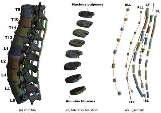
Figure 1.
Composition of the human spine finite element (FE) model: (a) Overall shape of the intact FE model, (b) FE model of an intervertebral disc composed of nucleus pulposus and annulus fibrosus, and (c) six major ligaments of the spine; 2-node link element.
Ansys Workbench software (Version 2019 R1, ANSYS Inc., Pittsburgh, PA, USA) was used for material property settings and mesh generation in the FE model. Element generation information of the FE model was as follows: the element type of the vertebral body corresponded to a hexahedral element, which consisted of 5278–7648 elements per segment. The IVD was created as a hexahedral element in a similar manner as that used in the vertebral body. The vertebral arch was a tetrahedral element, with 26,372 to 35,838 elements per segment. Furthermore, the screw was penetrated with a complex shape. Thus, more elements were created here than in other parts. The percentage of elements with a quality index over 0.85 (quality range: 0~1) was 92.09%. Also, 72.87% of the total number of elements were trilinear hexahedral while the rest corresponded to linear tetrahedra. We created an FE model that seemed like a vertebral arch of a complex shape with high quality elements.
2.2.2. Spinal Fracture
Four previous study models were referenced to generate the fractured spine model [32,34,35,36]. Each study conducted a comparative analysis according to the screw type, fracture level, and CS screw insertion angle. Although the final goals were different, all the models used the same fixed segments and fracture implementation methods. The fixed site was T12-L2, and the fracture was implemented by removing part of the vertebral body of L1. However, in this study, a method of lowering the Young’s modulus of the vertebra was chosen to design the fractured spine model [37,38]. The method of implementing a geometric fracture is the method used in Liu et al.’s study [39]. This method calculated the defect volume inside the fractured spine and removed the defect site. Here, as for the bony defect area, the front side is the anterior margin of the vertebral body, the upper side is a transection paralleled to the upper endplate, and the lower side is an oblique section paralleled to the kyphotic correction angle. The main point here is that the size of the fracture site and the defect site is different for each patient according to the severity of the fracture. Liu et al.’s study also selected fracture severity for a specific fracture patient as a representative model. Of course, as in Zhou et al. [14], fracture severity can be classified into moderate fractures and severe fractures. However, since this method requires direct modification of the geometry, this study adopted a method of implementing a fracture by adjusting the material properties so that the location and severity of the fracture can be adjusted without modifying the geometry.
We are only comparing the effects of different fixation segments and screw types on the stability of a fracture. The material properties of the rest of the vertebrae have a minor effect on such spine stability (the basic requirement to protect structures and prevent the early mechanical deterioration of spinal components [40]), so, we have maintained the properties of healthy bone in the rest of the vertebrae of the column. The method of fixation complements the upper and lower sections based on short-segmented fixation. As mentioned above, the screw type was either PS or CS, and the typical trajectory was selected based on the shape of the spine.
Figure 2 shows the results of applying stress on the screw, obtained by constantly reducing the Young’s modulus of the vertebra using FEA. In this Figure 2, Y1 denotes the Young’s modulus of the normal state (defined in a posterior fixed state without fracture), Y2 is half of Y1, Y3 is half of Y2, Y4 is 1/10 of Y1, Y5 is half of Y4, Y6 is 1/100 of Y1, and Y7 denotes the Young’s modulus of the FE model with the T12 segment completely removed. In this manner, the Young’s modulus of the vertebra was reduced at a constant rate, and the stress on the screw due to the decrease in the stiffness of the vertebra was calculated using FEA. A simulation was performed, wherein the stress on the spinal implant increased due to the fractured spine. The results of the simulation were compared with those in reference studies to determine the rate of reduction of Young’s modulus of the vertebra that leads to a fracture [32]. To minimize the error of the results, a simulation was performed by implementing the fractured state of L1 in the T12-L2 fixation, as described in a comparative study. The equivalent stress of the screws obtained under similar conditions is summarized in Table 2. The fracture shape of the comparative paper [14,32] is the same as that of Liu et al.’s study mentioned above [39], and the physical properties of all vertebrae are the same as normal (including the fracture site). This study reduced the Young’s modulus (cortical bone and cancellous bone) of the entire fracture site. When the equivalent stress of the screw by flexion motion was calculated under almost the same conditions as in the reference study, the Young’s modulus of the vertebra was found to be almost the same as the value in the reference study at the Y5 point (5% of the normal state). Accordingly, assuming a vertebral fracture, the Young’s modulus at the fracture site was reduced to 95% that of the normal state.
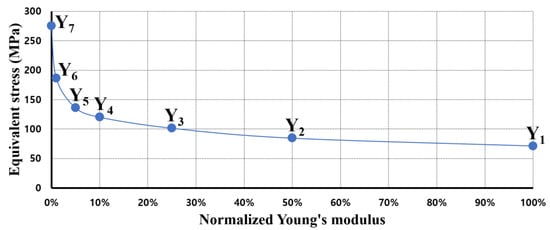
Figure 2.
Equivalent stress of pedicle screw for spinal fixation when compared to Young’s modulus of vertebra.
Table 2.
Comparison of equivalent stress results of screws; flexion motion analysis in the fractured state.
2.2.3. Fusion Model
The fixation model was created using Inventor software (Version 2019, Autodesk, Mill Valley, CA, USA) and inserted into the intact model. Given that T12 was fractured, the fusion model was generated via four methods: (1) T11-L1, (2) T10-T11-L1, (3) T11-L1-L2, and (4) T10-T11-L1-L2. The FE model was used to implement posterior spinal fixation with four fixation methods (Figure 3) [14,41].
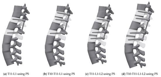
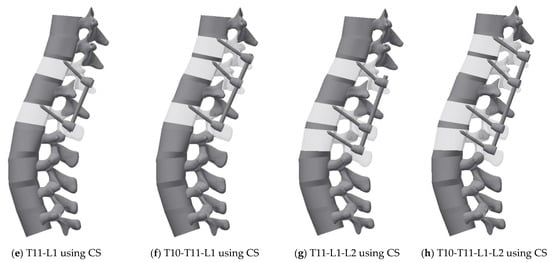
Figure 3.
3D geometric model for each case: (a) Pedicle screw fixation T11-L1, (b) Pedicle screw fixation T10-T11-L1, (c) Pedicle screw fixation T11-L1-L2, (d) Pedicle screw fixation T10-T11-L1-L2, (e) Cortical screw fixation T11-L1, (f) Cortical screw fixation T10-T11-L1, (g) Cortical screw fixation T11-L1-L2, and (h) Cortical screw fixation T10-T11-L1-L2.
Two types of fixation screws were used: a PS and a CS. The diameter of the spinal rod of the spinal fixation device was 6 mm, and the length of the rod matched the distance of the fixed segment. The material properties of spinal rod and screw are titanium alloy [42], and the contacts between the vertebrae and the screw are bonded, and the geometric information of PS and CS is as follows: the diameter and length of the PS were 6 mm and 60 mm, respectively. The screw thread was input with a mean pitch diameter of 5.1 mm, pitch of 1.5 mm, and thread angle of 45° using the virtual thread implementation function of Ansys software. The diameter of the CS is 4.5 mm and the total length is 45 mm. The screw thread was input with a mean pitch diameter of 4.1 mm, pitch of 1.5 mm, and thread angle of 45°. The diameter and length of the CS are lower than those of the PS, and the trajectory does not penetrate the pedicle but mainly penetrates the cortical bone of the vertebral body [17,18,43].
2.3. Boundary and Loading Conditions
The vertebral body and IVD were bonded without gaps, and the ALL and PLL were connected between the vertebral body. In the vertebral arch, all ligaments, except the ALL and PLL, were connected to each other between the upper and lower segments at the posterior of the spine. A virtual thread contact condition was applied to the screw and segment of the fixed part. The loading condition was based on an in vitro study in which the multilevel lumbar spine was subjected to the maximum possible load without causing spinal injury [23,43]. For all physiological motions, i.e., flexion, extension, lateral bending, and axial rotation, the preload and moment were placed on the upper surface of the T10 level. Additionally, all degrees of freedom were restricted to the lower surface of the L5 spine of this model to support the load. Regardless of the motion, a preload of 150 N was applied for all the motions (flexion, extension, lateral bending, axial rotation), and moments (7.5 Nm, 7.5 Nm, 7.8 Nm and 5.5 Nm, respectively) were applied for each motion based on the boundary conditions as described in a previous study [44]. The values of pre-load and moment are summarized in Table 3.
Table 3.
Load for the simulation of each motion.
3. Results
3.1. Model Validation
The shape of each FE model, material properties, and boundary conditions were not completely consistent, and there were slight differences. To validate the model in the same state as in the reference model to the maximum possible extent, segments ranging from L1 to L5 (some reference models also include S1) were created and the same loading conditions were applied [44]. The validation factor was the range of motion (ROM) generated by each pure moment and L4-5 intradiscal pressure under the compression load. In each motion, the pure moment is identical to the conditions specified in Table 2. Regarding the L4-5 intradiscal pressure, the compression force applied to the IVD was calculated by applying 1000 N to the upper surface of the L1 level.
As shown in Figure 4, the ROM in this study was within the range of the reference data and was slightly lower than that in the in vitro data. The result indicates that the stiffness of the FE model in this study slightly exceeds that of the cadaver. Conversely, L4-L5 intradiscal pressure is included within the error range of in vitro data and within the range of the reference model results, thereby confirming that the properties of the IVD material of this model were almost identical to those of the cadaver. This finding verified that the FE model in this study did not significantly differ from that in the previous study in terms of simulation performance [33].
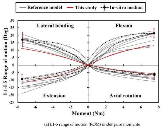
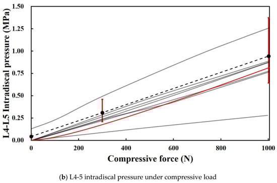
Figure 4.
ROMs and intervertebral disc (IVD) pressure in the present study and extant study: (a) Data from eight previous studies and the present study on ROM with respect to motion. Black dotted lines represent the median curves of 10 L1-5 specimens [44,48]. The red ranges denote the range of results for a moment corresponding to 7.5 Nm. (b) Data from eight previous studies and present study on intradiscal pressure between L4 and L5 with respect to flexion. Black dotted line and red ranges denote the median relationship for 15 L4-5 segments, and its range of results for 0 N, 300 N, and 1000 N [44,49].
3.2. Range of Motion
Figure 5 shows the difference between the ROM of the spine with posterior spinal fusion and that of the intact model when the T12 segment is fractured. ROM of the intact model was a flexion of 13.4°, extension of 11.1°, lateral bending of 11.2°, and axial rotation of 6.6°. A retrospective study investigated the ROM in patients with thoracolumbar vertebral fractures and found that the ROM in those who underwent spinal fixation surgery in the adjacent segments was reduced by 50% compared to normal ROM [50]. Subsequent studies demonstrated that the ROM of the thoracic and lumbar spine in patients undergoing surgical treatment for vertebral fractures was lower than that healthy people, but the underlying mechanism was not identified [51]. In this study, when a PS was used, the average ROM decreased by 2.05° compared to that of the normal spine, and when a CS was used, the average ROM decreased by 3.875°; the finding is consistent with that in the above clinical study. These results suggest that the fixation mechanism of the fractured spine directly limits the motion of the spine. In flexion, the T11-L1-L2 fixation using a PS leads to the most common result among all cases. The value of extension is the same as that of flexion, and only the reverberation is the opposite. However, the most common result in the intact model was T10-T11-L1 fixation using a CS, and the largest difference of the ROM was observed with T10-T11-L1-L2 fixation using a CS. T11-L1-L2 fixation using a CS exhibited the lowest ROM in lateral bending. In addition, the average ROM was 4.9° lower than that of the intact model, and this result corresponds to the smallest average value among all motions. In the axial rotation, the ROM of T11-L1-L2 fixation using a PS was similar to that in the intact model. Overall, T11-L1-L2 fixation using a PS led to similar ROM to that in the intact model, and the largest difference in ROM was observed in T11-L1-L2 fixation using a CS.
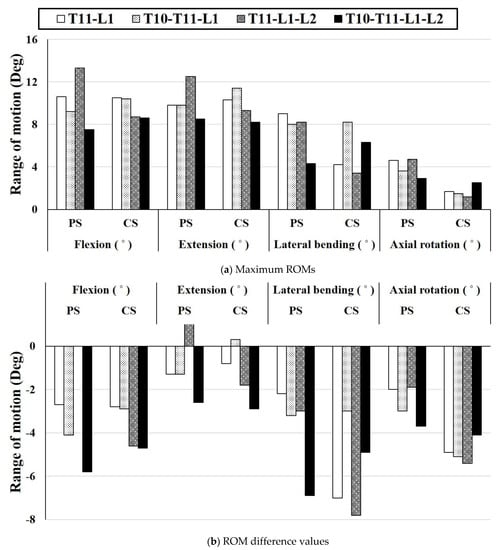
Figure 5.
Comparison of the difference between the ROM result and intact model for all cases: (a) Maximum ROM for each motion based on the fixing method, (b) Difference value between ROM of the intact model and ROM based on each fixing method.
3.3. Equivalent Stress
3.3.1. Equivalent Stress on a Screw
The stress applied to the screw was calculated for each motion using FEA. Figure 6 shows the screw stress in each case. According to Wang et al.’s study [36], in the case of two-segment fixation (T12-L2) in the fractured spine, the stress received by a CS was higher than that received by a PS when lateral bending was performed. Conversely, in other motions, the stress received by a PS was higher than that received by a CS. As shown in Figure 6, our study also showed the same stress tendency. The average stress generated by each motion was named as the motion average stress, and the stress level for each fixing method was compared using the motion average stress. The highest motion average stress was 321.6 MPa, which was observed in T10-T11-L1 extension using a PS in the normal state. In addition, the low motion average stress levels in T11-L1-L2 using a PS and in T11-L1-L2 using a CS were 69.0 MPa and 86.9 MPa, respectively. The stress reduction rate based on the screw type in the same fixation method in the fractured state is described below. In the case of T11-L1 fixation, the motion average stress of the CS was 87.2 MPa, which was 19.3% lower than that using a PS. Notably, the lowest value of single motion was 48.9 MPa, which was observed in the lateral bending motion with a PS. In the case of T10-T11-L1 fixation, the motion average stress of the PS was 87.4 MPa, which was 24.3% lower than that of the CS. In the case of T11-L1-L2 fixation, the motion average stress of the PS was 69.0 MPa, which was 20.6% less than that of the CS. In the case of T10-T11-L1-L2 fixation, the motion average stress of the CS was 53 MPa, which is 27.4% lower than that of the PS, and this reduction rate was the highest among all cases. The motion average stress in the CS exceeded that in the PS in the fixation of three segments or more because high stress occurs in the part where the vertebral arch edge and screw head make contact due to the trajectory characteristics of a CS.
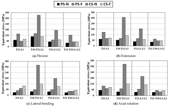
Figure 6.
Equivalent stress applied to the screw via pure moment: (a) equivalent stress of screw in flexion, (b) equivalent Scheme 11. L2, T10-L11-L1, T11-L1-L2, T10-T11-L1-L2.
3.3.2. Equivalent Stress of Peri-Implant Bone
As shown in Figure 7, the stress tendency of the PIB is similar to that of the screw. Similar to the tendency of stress on the screw, the highest motion average stress was detected in T10-T11-L2 fixation using a CS in the normal state. The motion average stress of the T11-L1-L2 fixed motion using a PS was 20.0 MPa, which was the lowest among all cases. The motion average stress of T11-L1 using a CS was 21.6 MPa, which is almost the same as that of T11-L1-L2. The stress applied to the PIB was significantly reduced by the screw under the same fixation conditions. In the case of T11-L1 fixation, the motion average stress in the case using CS decreased by 57% compared to that using a PS. In the case of T10-T11-L1 fixation, the motion average stress of a PS was reduced by 47.6% compared to that of a CS. In some cases, the stress in the fractured state was lower than that in the normal state. In the T10-T11-L1 fixation, the PS and CS exhibited a stress reduction in the fractured state. The magnitude of stress in a PS was 8.3 MPa lower than that in a CS. However, the reduction rate of stress due to the change in the stiffness of a specific segment was 20.5% in a PS and 64.4% in a CS. In the case of T11-L1-L2 fixation, the motion average stress with the use of a PS decreased by 67.6% compared to that with the use of a CS, which was the highest reduction rate in all cases.
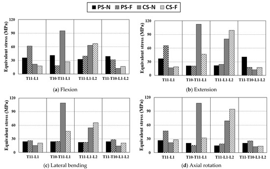
Figure 7.
Equivalent stress applied to peri-implant bone by the pure moment: (a) equivalent stress of peri-implant bone in flexion, (b) equivalent stress of peri-implant bone in extension, (c) equivalent stress of peri-implant bone in lateral bending, and (d) equivalent stress of peri-implant bone in axial rotation.
3.3.3. Equivalent Stress of IVD
Figure 8 summarizes the equivalent stress of the IVD between fixed sites. In the case of T10-T11-L1 fixation, the IVDs between T10 and L1, namely, T10-11, T11-T12, and T12-L1, could be used to compute the maximum equivalent stress of the three IVDs. Overall, a uniform trend was observed although T11-L1 fixation using a CS exhibited higher stress than other cases in lateral bending. In this case, there was no peculiarity, even in the equivalent stress of the screw or PIB. Thus, it is difficult to determine a clear cause. The overall trend was that the equivalent stress of the IVD was lower for a CS than that for a PS, and the equivalent stress applied to an IVD was up to 22.2% lower in the T10-T11-L1 fixed state when a CS was used than when a PS was used. With respect to the method of fixation, T11-L1, T11-L1-L2, and T10-T11-L1-L2 exhibited low-stress tendencies similarly. Among them, the IVD motion average stress of T11-T10-L1-L2 fixation with a PS was the lowest. Hence, the fixation method that applies the least equivalent stress to the IVD is T10-T11-L1-L2 fixation using a CS [52,53].
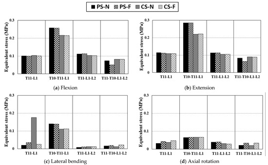
Figure 8.
Equivalent stress applied to IVD via pure moment: (a) equivalent stress of IVD in flexion, (b) equivalent stress of IVD in extension, (c) equivalent stress of IVD in lateral bending, and (d) equivalent stress of IVD in axial rotation.
4. Discussion
In this study, we compared the stability of the spine in several cases by simulating the procedure of posterior spinal fusion in patients with vertebral fractures and calculating equivalent stress in each case. The spine generates moments through various motions. In this study, the average ROM and equivalent stress generated by the four basic motions of the spine were classified as the motion average stress, and the stability of the spine was evaluated using this stress.
First, the correct ROM after spinal fixation surgery directly affects the stability of the spine and spinal implants and improves a patient’s quality of life. The occurrence of excessive ROM increases stress on the adjacent disk and potentially increases the risk of developing adjusted segment degeneration (ASD) [54]. Conversely, if the ROM is low, the intervertebral load transfer is not smooth due to excessive fixation [55]. Hence, the optimal criterion for ROM after spinal fixation was set as the ROM of the intact model in the study. We found T11-L1-L2 fixation using a PS led to the optimal ROM; the average ROM was −0.87°, which differs from that of the intact model but is similar to that of the intact model at the maximum possible extent. Conversely, the lowest ROM was observed in T11-L1-L2 fixation using a CS, potentially because the load generated from the upper part might not be transferred correctly due to excessive fixation.
Second, increased stress applied to the screw of the spinal implant increases the possibility of fixation failure due to screw damage. The vertebra of the fractured vertebral segment loses load transmission and support, and thus the load applied to the fixation screw increases. When a PS was used in the simulation in this study, the stress applied to the screw in the fractured state exceeded that in the normal state. The highest stress generation point of the screw is around the screw head. A spinal rod is connected to the screw head, and this process has a complex shape. The stress concentration can occur during contact due to deformation because of load transfer. To prevent this stress concentration, it is necessary to modify the screw head design such that the spinal rod does not contact the vertebral arch maximally or modify the screw trajectory [17]. The equivalent stress applied to a CS is lower in the fractured state than in the normal state because of the small screw diameter and trajectory characteristics of a CS. In general, the bending moment of a CS received by the screw stress is lower than that of a PS due to the relatively short screw length. Therefore, in the case of long-segment fixation, it is expected that the risk of damage to the spinal implant is significantly lower in a CS than in a PS. When the lowest stress occurs in the screw, T10-T11-L1-L2 is fixed using a CS, and a significant difference is absent even in T10-T11-L1 fixation using a PS.
Third, high stress on the PIB can increase the possibility of damage to the vertebra with lower stiffness than the screw and cause screw fixation failure. The stress applied to the PIB at the fractured state was the highest at T11-L1-L2 fixation using a CS and lowest at T10-T11-L1-L2 fixation using a CS. This result was similar to the result of the stress on the screw. In the case of a PS, the stress in the fractured state consistently exceeded that in the normal state. However, when using a CS, the stress tendencies before and after fractures were different in the same fixation method. T10-T11-L1 fixation using a CS exhibited a high ROM and low screw and PIB stress. Conversely, compared to other cases, T11-L1-L2 exhibited a lower ROM and lower stress on the screw but higher stress on the PIB. If the flexible state and the strong restraint are distinguished through the ROM, the stress applied to the screw and BIP in the flexible state simultaneously decreases. In the case of the strong restraint, more load was placed on the PIB than on the screw.
Finally, the stress applied to the IVD was low, and there was no significant difference in the magnitude of the stress based on the fixation method. Thus, it is difficult to determine the advantages and disadvantages of the fixation method solely with the stress values of the IVD. However, if an efficient fixation method is selected numerical data regarding the motion average stress, T11-L1-L2 fixation applies the least stress to the IVD, and it has a slight advantage over other fixation methods depending on the screw type.
As a result, the T10-T11-L1-L2 fixation method using a CS on the fractured spine places the least burden on the screw and vertebra. However, studies have shown that using fixation of a segment as short as possible is more desirable than fixing at the expense of unfractured segments for ROM optimization. Therefore, it may be reasonable to choose T10-T11-L1 fixation using a PS, which applies relatively high stress (2.5 MPa) to the PIB, or T11-L1 fixation using a CS, which applies high stress (4.2 MPa) to the PIB. However, since minimization of spinal fixation segments requires a comprehensive judgment according to the patient’s condition, further studies are needed to determine to what extent it is necessary to minimize the fixation segments while withstanding the increase in pressure applied to the PIB.
The present study has several limitations. First, the muscles were not included in the model. Spine motion simulation involving the muscles can be used to analyze biomechanical behavior for additional external forces in addition to the basic four motions. Second, this study analyzed several surgical methods using a single FE model. Therefore, it is unreasonable to uniformly apply the results of this study to models of different shapes.
5. Conclusions
The PS and CS have advantages and disadvantages depending on the fixation method. Our findings indicate that the T10-T11-L1-L2 fixation method using a CS for the fractured spine places the least burden on the screw and the vertebra.
Author Contributions
Conceptualization, S.M.S. and C.-S.L.; methodology, C.-J.K.; software, C.-J.K.; validation, S.M.S., S.H.C. and C.-J.K.; formal analysis, C.-J.K. and C.-S.L.; investigation, C.-J.K., T.S.G. and C.-S.L.; resources, T.S.G. and J.S.L.; data curation, S.M.S., S.H.C., C.-J.K. and C.-S.L.; writing—original draft preparation, C.-J.K. and C.-S.L.; writing—review and editing, S.M.S., S.H.C., C.-J.K. and C.-S.L.; visualization, C.-J.K.; supervision, J.S.L. and C.-S.L.; project administration, S.M.S. and C.-S.L.; funding acquisition, S.M.S., S.H.C. and C.-S.L. All authors have read and agreed to the published version of the manuscript.
Funding
This research was supported by the Basic Science Research Program through the National Research Foundation of Korea (NRF), funded by the Ministry of Education. (No. NRF-2018R1D1A1B07051376, SMS; No. NRF-2018R1D1A1B07051146, SHC). This study was also supported by the National Research Foundation of Korea (NRF) grant funded by the Korean Government (MSIT). (No. NRF-2019R1F1A1062037, CSL).
Institutional Review Board Statement
The study was conducted according to the guidelines of the Declaration of Helsinki and approved by the Institutional Review Board of Pusan National University Hospital (IRB No. H-2011-031-097).
Informed Consent Statement
Informed consent was obtained from all subjects involved in the study.
Data Availability Statement
Not applicable.
Conflicts of Interest
The authors declare no conflict of interest. The funders had no role in the study design, data collection and analyses, writing of the manuscript, or in the decision to publish the results.
References
- Wang, X.-Y.; Dai, L.-Y.; Xu, H.-Z.; Chi, Y.-L. Biomechanical effect of the extent of vertebral body fracture on the thoracolumbar spine with pedicle screw fixation: An in vitro study. J. Clin. Neurosci. 2008, 15, 286–290. [Google Scholar] [CrossRef]
- Aono, H.; Tobimatsu, H.; Ariga, K.; Kuroda, M.; Nagamoto, Y.; Takenaka, S.; Furuya, M.; Iwasaki, M. Surgical outcomes of temporary short-segment instrumentation without augmentation for thoracolumbar burst fractures. Injury 2016, 47, 1337–1344. [Google Scholar] [CrossRef]
- Watanabe, K.; Lenke, L.G.; Bridwell, K.H.; Kim, Y.J.; Koester, L.; Hensley, M. Proximal junctional vertebral fracture in adults after spinal deformity surgery using pedicle screw constructs: Analysis of morphological features. Spine 2010, 35, 138–145. [Google Scholar] [CrossRef]
- Jindal, N.; Sankhala, S.; Bachhal, V. The role of fusion in the management of burst fractures of the thoracolumbar spine treated by short segment pedicle screw fixation: A prospective randomised trial. J. Bone Jt. Surg. 2012, 94, 1101–1106. [Google Scholar] [CrossRef]
- Schmidt, H.; Heuer, F.; Simon, U.; Kettler, A.; Rohlmann, A.; Claes, L.; Wilke, H.-J. Application of a new calibration method for a three-dimensional finite element model of a human lumbar annulus fibrosus. Clin. Biomech. 2006, 21, 337–344. [Google Scholar] [CrossRef]
- Pitzen, T.; Geisler, F.; Matthis, D.; Müller-Storz, H.; Barbier, D.; Steudel, W.-I.; Feldges, A. A finite element model for predicting the biomechanical behaviour of the human lumbar spine. Control Eng. Pract. 2002, 10, 83–90. [Google Scholar] [CrossRef]
- Liebschner, M.A.; Kopperdahl, D.L.; Rosenberg, W.S.; Keaveny, T.M. Finite element modeling of the human thoracolumbar spine. Spine 2003, 28, 559–565. [Google Scholar] [CrossRef]
- Huynh, K.T.; Gao, Z.; Gibson, I.; Lu, W.F. Haptically integrated simulation of a finite element model of thoracolumbar spine combining offline biomechanical response analysis of intervertebral discs. Comput. Aided Des. 2010, 42, 1151–1166. [Google Scholar] [CrossRef]
- Areias, B.; Caetano, S.; Sousa, L.; Parente, M.; Jorge, R.; Sousa, H.; Gonçalves, J. Numerical simulation of lateral and transforaminal lumbar interbody fusion, two minimally invasive surgical approaches. Comput. Methods Biomech. Biomed. Eng. 2020, 23, 408–421. [Google Scholar] [CrossRef]
- Fidalgo, D.; Areias, B.; Sousa, L.; Parente, M.; Jorge, R.; Sousa, H.; Gonçalves, J. Minimally invasive transforaminal and anterior lumbar interbody fusion surgery at level L5-S1. Comput. Methods Biomech. Biomed. Eng. 2020, 23, 384–395. [Google Scholar] [CrossRef]
- Schmidt, H.; Heuer, F.; Drumm, J.; Klezl, Z.; Claes, L.; Wilke, H.-J. Application of a calibration method provides more realistic results for a finite element model of a lumbar spinal segment. Clin. Biomech. 2007, 22, 377–384. [Google Scholar] [CrossRef]
- Xu, M.; Yang, J.; Lieberman, I.H.; Haddas, R. Lumbar spine finite element model for healthy subjects: Development and validation. Comput. Methods Biomech. Biomed. Eng. 2017, 20, 1–15. [Google Scholar] [CrossRef]
- Hsieh, Y.-Y.; Tsuang, F.-Y.; Kuo, Y.-J.; Chen, C.-H.; Chiang, C.-J.; Lin, C.-L. Biomechanical analysis of single-level interbody fusion with different internal fixation rod materials: A finite element analysis. BMC Musculoskelet. Disord. 2020, 21, 100. [Google Scholar] [CrossRef]
- Zhou, Y.; Xin, D.; Lei, Z.; Zuo, Y.; Zhao, Y. Comparative Three-Dimensional Finite Element Analysis of 4 Kinds of Pedicle Screw Schemes for Treatment of Adult Degenerative Scoliosis. Med. Sci. Monit. Int. Med. J. Exp. Clin. Res. 2020, 26, e922050–e922051. [Google Scholar]
- Santoni, B.; Hynes, R.; McGilvray, K.; Rodriguez-Canessa, G.; Lyons, A.; Henson, M.; Womack, W.; Puttlitz, C. Cortical bone trajectory for lumbar pedicle screws. Spine J. 2009, 9, 366–373. [Google Scholar] [CrossRef]
- Feng, Z.-H.; Li, X.-B.; Tian, N.-F.; Sheng, S.-R.; Li, Y.M.; Phan, K.; Lin, Z.-K.; Joaquim, A.F.; Xuan, J.; Lin, Y. The technique of cortical bone trajectory screw fixation in spine surgery: A comprehensive literature review. AME Med. J. 2018. [Google Scholar] [CrossRef]
- Akpolat, Y.T.; Inceoglu, S.; Kinne, N.; Hunt, D.; Cheng, W.K. Fatigue performance of cortical bone trajectory screw compared with standard trajectory pedicle screw. Spine 2016, 41, E335–E341. [Google Scholar] [CrossRef]
- Baluch, D.A.; Patel, A.A.; Lullo, B.; Havey, R.M.; Voronov, L.I.; Nguyen, N.-L.; Carandang, G.; Ghanayem, A.J.; Patwardhan, A.G. Effect of physiological loads on cortical and traditional pedicle screw fixation. Spine 2014, 39, E1297–E1302. [Google Scholar] [CrossRef] [PubMed]
- Matsukawa, K.; Yato, Y.; Kato, T.; Imabayashi, H.; Asazuma, T.; Nemoto, K. In vivo analysis of insertional torque during pedicle screwing using cortical bone trajectory technique. Spine 2014, 39, E240–E245. [Google Scholar] [CrossRef]
- Goh, T.S.; Lim, B.-Y.; Lee, J.S.; Lee, C.-S. Identification of surgical plan for syndesmotic fixation procedure based on finite element method. Appl. Sci. 2020, 10, 4349. [Google Scholar] [CrossRef]
- Lim, B.-Y.; Kim, Y.; Hoseok, I.; Lee, C.-S. Numerical investigation of the sternoclavicular joint modeling technique for improving the surgical treatment of pectus excavatum. Sci. Rep. 2020, 10, 7357. [Google Scholar] [CrossRef]
- Shin, J.K.; Lim, B.-Y.; Goh, T.S.; Son, S.M.; Kim, H.-S.; Lee, J.S.; Lee, C.-S. Effect of the screw type (S2-alar-iliac and iliac), screw length, and screw head angle on the risk of screw and adjacent bone failures after a spinopelvic fixation technique: A finite element analysis. PLoS ONE 2018, 13, e0201801. [Google Scholar] [CrossRef]
- Zhong, Z.; Chen, S.; Hung, C.-H. Load-and displacement-controlled finite element analyses on fusion and non-fusion spinal implants. Proc. Inst. Mech. Eng. Part H J. Eng. Med. 2009, 223, 143–157. [Google Scholar] [CrossRef]
- Goel, V.K.; Kong, W.; Han, J.S.; Weinstein, J.N.; Gilbertson, L.G. A combined finite element and optimization investigation of lumbar spine mechanics with and without muscles. Spine 1993, 18, 1531–1541. [Google Scholar] [CrossRef]
- Chen, C.-S.; Cheng, C.-K.; Liu, C.-L.; Lo, W.-H. Stress analysis of the disc adjacent to interbody fusion in lumbar spine. Med. Eng. Phys. 2001, 23, 485–493. [Google Scholar] [CrossRef]
- Chuang, W.-H.; Kuo, Y.-J.; Lin, S.-C.; Wang, C.-W.; Chen, S.-H.; Chen, Y.-J.; Hwang, J.-R. Comparison among load-, ROM-, and displacement-controlled methods used in the lumbosacral nonlinear finite-element analysis. Spine 2013, 38, E276–E285. [Google Scholar] [CrossRef]
- Kim, Y.-H.; Jung, T.-G.; Park, E.-Y.; Kang, G.-W.; Kim, K.-A.; Lee, S.-J. Biomechanical efficacy of a combined interspinous fusion system with a lumbar interbody fusion cage. Int. J. Precis. Eng. Manuf. 2015, 16, 997–1001. [Google Scholar] [CrossRef]
- Dooris, A.P.; Goel, V.K.; Grosland, N.M.; Gilbertson, L.G.; Wilder, D.G. Load-sharing between anterior and posterior elements in a lumbar motion segment implanted with an artificial disc. Spine 2001, 26, E122–E129. [Google Scholar] [CrossRef]
- Ayturk, U.M.; Garcia, J.J.; Puttlitz, C.M. The micromechanical role of the annulus fibrosus components under physiological loading of the lumbar spine. J. Biomech. Eng. 2010, 132, 061007. [Google Scholar] [CrossRef]
- Mustafy, T.; El-Rich, M.; Mesfar, W.; Moglo, K. Investigation of impact loading rate effects on the ligamentous cervical spinal load-partitioning using finite element model of functional spinal unit C2–C3. J. Biomech. 2014, 47, 2891–2903. [Google Scholar] [CrossRef]
- Casaroli, G.; Galbusera, F.; Jonas, R.; Schlager, B.; Wilke, H.-J.; Villa, T. A novel finite element model of the ovine lumbar intervertebral disc with anisotropic hyperelastic material properties. PLoS ONE 2017, 12, e0177088. [Google Scholar] [CrossRef] [PubMed]
- Li, J.; Zhang, L.-C.; Li, J.; Zhang, H.; Zhao, J.-X.; Zhang, W. A Hybrid Uniplanar Pedicle Screw System with a New Intermediate Screw for Minimally Invasive Spinal Fixation: A Finite Element Analysis. Biomed Res. Int. 2020, 2020, 5497030. [Google Scholar] [PubMed]
- Kim, C.-J.; Son, S.M.; Heo, J.-Y.; Lee, C.-S. Spinal Stability Evaluation According to the Change in the Spinal Fixation Segment Based on Finite Element Analysis. J. Comput. Struct. Eng. Inst. Korea 2020, 33, 145–152. [Google Scholar] [CrossRef]
- Zhou, F.; Yang, S.; Liu, J.; Lu, J.; Shang, D.; Chen, C.; Wang, H.; Ma, J. Finite element analysis comparing short-segment instrumentation with conventional pedicle screws and the Schanz pedicle screw in lumbar 1 fractures. Neurosurg. Rev. 2020, 43, 301–312. [Google Scholar] [CrossRef]
- Liu, J.; Yang, S.; Zhou, F.; Lu, J.; Xia, C.; Wang, H.; Chen, C. The feasibility of short-segment Schanz screw implanted in an oblique downward direction for the treatment of lumbar 1 burst fracture: A finite element analysis. J. Orthop. Surg. Res. 2020, 15, 1–11. [Google Scholar]
- Wang, T.N.; Wu, B.L.; Duan, R.M.; Yuan, Y.S.; Qu, M.J.; Zhang, S.; Huang, W.; Liu, T.; Yu, X.B. Treatment of Thoracolumbar Fractures Through Different Short Segment Pedicle Screw Fixation Techniques: A Finite Element Analysis. Orthop. Surg. 2020, 12, 601–608. [Google Scholar] [CrossRef]
- Polikeit, A.; Nolte, L.P.; Ferguson, S.J. The effect of cement augmentation on the load transfer in an osteoporotic functional spinal unit: Finite-element analysis. Spine 2003, 28, 991–996. [Google Scholar] [CrossRef]
- Salvatore, G.; Berton, A.; Giambini, H.; Ciuffreda, M.; Florio, P.; Longo, U.G.; Denaro, V.; Thoreson, A.; An, K.-N. Biomechanical effects of metastasis in the osteoporotic lumbar spine: A Finite Element Analysis. BMC Musculoskelet. Disord. 2018, 19, 38. [Google Scholar] [CrossRef]
- Liu, J.; Yang, S.; Lu, J.; Fu, D.; Liu, X.; Shang, D. Biomechanical effects of USS fixation with different screw insertion depths on the vertebrae stiffness and screw stress for the treatment of the L1 fracture. J. Back Musculoskelet. Rehabil. 2018, 31, 285–297. [Google Scholar] [CrossRef]
- Izzo, R.; Guarnieri, G.; Guglielmi, G.; Muto, M. Biomechanics of the spine. Part I: Spinal stability. Eur. J. Radiol. 2013, 82, 118–126. [Google Scholar] [CrossRef]
- Phan, K.; Hogan, J.; Maharaj, M.; Mobbs, R.J. Cortical bone trajectory for lumbar pedicle screw placement: A review of published reports. Orthop. Surg. 2015, 7, 213–221. [Google Scholar] [CrossRef]
- Kang, K.-T.; Koh, Y.-G.; Son, J.; Yeom, J.S.; Park, J.-H.; Kim, H.-J. Biomechanical evaluation of pedicle screw fixation system in spinal adjacent levels using polyetheretherketone, carbon-fiber-reinforced polyetheretherketone, and traditional titanium as rod materials. Compos. Part B Eng. 2017, 130, 248–256. [Google Scholar] [CrossRef]
- Yamamoto, I.; Panjabi, M.M.; Crisco, T.; Oxland, T. Three-dimensional movements of the whole lumbar spine and lumbosacral joint. Spine 1989, 14, 1256–1260. [Google Scholar] [CrossRef]
- Dreischarf, M.; Zander, T.; Shirazi-Adl, A.; Puttlitz, C.; Adam, C.; Chen, C.; Goel, V.; Kiapour, A.; Kim, Y.; Labus, K. Comparison of eight published static finite element models of the intact lumbar spine: Predictive power of models improves when combined together. J. Biomech. 2014, 47, 1757–1766. [Google Scholar] [CrossRef]
- Rohlmann, A.; Zander, T.; Rao, M.; Bergmann, G. Realistic loading conditions for upper body bending. J. Biomech. 2009, 42, 884–890. [Google Scholar] [CrossRef]
- Dreischarf, M.; Rohlmann, A.; Bergmann, G.; Zander, T. Optimised in vitro applicable loads for the simulation of lateral bending in the lumbar spine. Med. Eng. Phys. 2012, 34, 777–780. [Google Scholar] [CrossRef] [PubMed]
- Dreischarf, M.; Rohlmann, A.; Bergmann, G.; Zander, T. Optimised loads for the simulation of axial rotation in the lumbar spine. J. Biomech. 2011, 44, 2323–2327. [Google Scholar] [CrossRef]
- Rohlmann, A.; Neller, S.; Claes, L.; Bergmann, G.; Wilke, H.-J. Influence of a follower load on intradiscal pressure and intersegmental rotation of the lumbar spine. Spine 2001, 26, E557–E561. [Google Scholar] [CrossRef]
- Brinckmann, P.; Grootenboer, H. Change of disc height, radial disc bulge, and intradiscal pressure from discectomy. An in vitro investigation on human lumbar discs. Spine 1991, 16, 641–646. [Google Scholar] [CrossRef]
- Leferink, V.; Nijboer, J.; Zimmerman, K.; Veldhuis, E.; ten Vergert, E.; ten Duis, H. Thoracolumbar spinal fractures: Segmental range of motion after dorsal spondylodesis in 82 patients: A prospective study. Eur. Spine J. 2002, 11, 2–7. [Google Scholar] [CrossRef] [PubMed][Green Version]
- Post, R.; Leferink, V. Sagittal range of motion after a spinal fracture: Does ROM correlate with functional outcome? Eur. Spine J. 2004, 13, 489–494. [Google Scholar] [CrossRef] [PubMed][Green Version]
- Ambati, D.V.; Wright, E.K., Jr.; Lehman, R.A., Jr.; Kang, D.G.; Wagner, S.C.; Dmitriev, A.E. Bilateral pedicle screw fixation provides superior biomechanical stability in transforaminal lumbar interbody fusion: A finite element study. Spine J. 2015, 15, 1812–1822. [Google Scholar] [CrossRef]
- Dicko, A.H.; Tong-Yette, N.; Gilles, B.; Faure, F.; Palombi, O. Construction and validation of a hybrid lumbar spine model for the fast evaluation of intradiscal pressure and mobility. Int. Sci. Index Med. Health Sci. 2015, 9, 134–145. [Google Scholar]
- Wang, B.; Hua, W.; Ke, W.; Lu, S.; Li, X.; Zeng, X.; Yang, C. Biomechanical evaluation of transforaminal lumbar interbody fusion and oblique lumbar interbody fusion on the adjacent segment: A finite element analysis. World Neurosurg. 2019, 126, e819–e824. [Google Scholar] [CrossRef]
- Chen, C.-S.; Cheng, C.-K.; Liu, C.-L. A Biomechanical Comparison of Posterolateral Fusion and Posterior Fusion in the Lumbar Spine. Clin. Spine Surg. 2002, 15, 53–63. [Google Scholar] [CrossRef]
Publisher’s Note: MDPI stays neutral with regard to jurisdictional claims in published maps and institutional affiliations. |
© 2021 by the authors. Licensee MDPI, Basel, Switzerland. This article is an open access article distributed under the terms and conditions of the Creative Commons Attribution (CC BY) license (https://creativecommons.org/licenses/by/4.0/).