Article

Dynamic Torque Coordinated Control Considering Engine Starting Conditions for a Power-Split Plug-In Hybrid Electric Vehicle

1
School of Vehicle and Mobility, Tsinghua University, Beijing 100084, China
2
State Key Laboratory of Mechanical Transmissions, Chongqing University, Chongqing 400044, China
3
Department of Mechanical Engineering, University of Michigan-Dearborn, Michigan, MI 48128, USA
*
Author to whom correspondence should be addressed.
Appl. Sci. 2021, 11(5), 2085; https://doi.org/10.3390/app11052085
Submission received: 28 January 2021 / Revised: 18 February 2021 / Accepted: 18 February 2021 / Published: 26 February 2021
(This article belongs to the Section Energy Science and Technology)

Abstract

:
For a power-split plug-in hybrid electric vehicle (PS-PHEV), the control system cannot effectively reduce jerks under some engine-starting conditions due to the pulsating torque of the engine, elastic characteristics of the transmission, battery power limitations, and the limitation of the maximum torque of the motor. To solve this problem, a dynamic torque-coordinated control method considering engine starting conditions (DTCC-ESC) is proposed in this paper. The proposed DTCC-ESC mainly includes three parts: the engine segment active control before and after engine ignition to minimize the impact of the engine ripple torque on the shocks of the powertrain system; the feedforward control of the engine starting conditions and the feedback control of the engine’s optimal target speed; and the active damping feedback compensation control for system resonance to reduce system vibrations. The results show that the proposed DTCC-ESC can effectively improve driving comfort under different engine starting conditions.

1. Introduction

The plug-in hybrid electric vehicle (PHEV) is one kind of new energy vehicle that has attracted widespread attention from automobile manufacturers [1]. Compared with traditional internal combustion engine (ICE) vehicles, PHEVs have better system efficiency, fuel economy and emission performance because the driver can choose different working modes [2,3]. During the mode-switching process of starting the engine, the vehicle driveline will often produce obvious shock and vibration. For a power-split PHEV, the engine ripple torque (ERT) will be directly transmitted to the powertrain system [4]. In the process of mode transition (MT), the transmitted ERT will cause obvious impacts and vibrations on the power transmission system, especially during engine starting [5,6]. Such transients make driving less comfortable and reduce the service life of the transmission.
Some control methods have been applied to the typical engine starting process to reduce vehicle shocks. Huang [7] formulated dynamic and economic shift schedules in an MT process and coordinated the motor torque to compensate for the fluctuation torque. In [8], considering the inertial torque of the motor, a motor compensation coordinated control strategy was designed to reduce unwanted jerks. Taking the speed fluctuation of engine and the fuel consumption rate as the control objective, Zuo [9] designed a mode-switching control strategy based on a logical threshold. Gao [10] proposed a control strategy of torque-dynamic coordination by means of a sliding mode control based on a disturbance compensation. These methods made the coordinated control strategy during MT process reduce vehicle jerks, but they ignored the influence of the ERT and elastic characteristics of the transmission system on the shocks of the powertrain.
Based on the data from an engine start-up test, researchers in [11,12] proposed a lookup table model of the ERT during engine start-up to estimate the engine pulsating torque and then used motors to compensate or offset the torque fluctuation of the powertrain. Canova [13] and Davis [14] set up a reduced-order engine thermodynamic model to estimate the ERT and used a belted starter/alternator to reduce the shocks and vibrations caused by ERT. Zhao [15] analyzed the MT process during the engine start-up and used engine torque estimation based on planetary dynamic equations to reduce vehicle jerks. In the implementation of such schemes, these methods helped estimate ERT to reduce vehicle jerks. Shen [16] designed a coordinated control strategy to determine target engine torque, motor torque, clutch torque and the moment of fuel injection to suppress vehicle jerks and improve riding comfort during engine start. Lin [17] divided the engine start into three phases, analyzed the influences of various parameters on the jerk in each phase, and then proposed a coordinated control strategy between the clutch pressure and motor torque and between the motor torque and engine torque. However, the influence of the elastic (stiffness–damping) characteristics of transmission on the powertrain vibrations was not taken into account.
Tomura [18] used the approximate function of ERT and the proportional feedback control of the speed difference to reduce the fluctuations of the powertrain. Wang [19] proposed an active damping-control strategy during the starting process to reduce the speed fluctuations of the transmission system. Su [20] used a staged torque estimation of the engine and an active damping-compensation control method based on drive shaft torque observations to reduce the jerks of the powertrain. Li [21] proposed a fuzzy control and a two degrees of freedom damping-control algorithm to reduce vehicle jerks. In these control methods, the ERT and the elastic characteristics of the transmission system were considered, but the influence of the limitations of battery-motor characteristics on vehicle jerks under different engine starting conditions was ignored.
In [22,23,24], the dynamic programming algorithm was used to analyze and formulate the optimal brake pressure, engine speed trajectory and control logic of MT process to minimize vehicle jerks. However, these methods cannot be applied to actual vehicle control.
In [25,26], the motor torque change rate was limited using dynamic equations of planetary gear to reduce vehicle jerks. Zeng [27] used feedforward control for one motor and compensation control for the other based on the engine torque estimation to improve driving comfort. Syed [28] designed an active damping-control system at the wheels to suppress system oscillation. Tang [29] designed a motor torque compensation control method and established a vibration path control to change the dynamic characteristics of the engine during starting and stopping. Zhu [30] divided the MT process into four operational stages and adopted the fuzzy gain scheduling proportion integration differentiation (PID) controller to reduce fluctuations of the powertrain system. To some extent, although the above methods can reduce vehicle jerks and vibrations, they also ignore the influence of the limitations of battery-motor characteristics on vehicle jerks under different engine starting conditions.
The above research during engine start-up for a hybrid powertrain system mainly focuses on the engine torque estimation, the limitation of the motor torque change rate, the compensation control based on the active damping and dynamic programming algorithm and so on. However, these methods do not fully consider the influence of factors such as ERT, the elastic characteristics of the transmission system, the battery power limitations or the maximum motor torque. In fact, these factors will diminish the effectiveness of the control system to reduce vehicle jerks under different engine starting conditions.
To solve this problem, this paper proposes a dynamic torque coordinated control method during engine starting conditions (DTCC-ESC). In comparison with previous research, the main contributions of this paper include the following three aspects: (1) In the MT process during engine starting, an engine segment active control method before and after engine ignition is proposed to minimize the impact of ERT on system jerks and vibrations; (2) During starting, the engine demand-angular acceleration is optimized to modify the feedforward control of the engine starting process before ignition; and (3) Based on the zero-pole distribution method and the estimation algorithms of the system torque and speed, an active-damping feedback compensation control for system resonance (ADFC-SR) is modified to restrain the vibrations of the transmission system. By this method, the torque of the engine output shaft fluctuations can be reduced; meanwhile the torque of the two motors to compensate or offset driveline fluctuations can be optimally distributed, so that the compensation torque from MG1 and MG2 will not exceed the limit of its own maximum torque. Therefore, vehicle jerks in some engine-starting conditions can be effectively reduced.
The rest of this article is organized as follows: In Section 2, the model of a compound power-split power transmission system is established, and this model has been verified by some experiments. In Section 3, the dynamic analysis during the engine starting process is carried out by using the equivalent lever method, and the problem to be solved in this paper is further described by using a flow chart. To address this problem, the DTCC-ESC method is proposed in Section 4. Then, in Section 5, the three control methods are simulated and compared under different engine-starting conditions. Finally, the simulation conclusions of the proposed control method are provided in Section 6.

2. Powertrain Dynamic Model

Figure 1 shows a compound power-split plug-in hybrid electric vehicle (PS-PHEV), which is studied in this article. The compound PS-PHEV includes an engine, a power battery pack, two motors, a compound power-split transmission based on a Ravigneaux planetary gear train, two brakes (B1 and B2), a torsional damper spring (TDS) and a main reducer and differential. The Ravigneaux planetary gear train includes the small sun gear S1, the large sun gear S2, the front short planetary gear Pb, the rear long planetary gear Pa, the front and rear common planet carrier C, and the front and rear common gear ring R. In the powertrain system of the compound PS-PHEV, the engine is connected to the planet carrier C through the TDS. The planet carrier C can be braked by the brake B1. The MG1 connects to the sun gear S1, which can be braked by the brake B2. The MG2 connects to the large sun gear S2. The ring gear R is the output terminal of power, which is directly connected to the final drive.
A powertrain plant model will be established using MATLAB/Simulink based on formulations and look-up tables as follows:

2.1. Dynamic Engine Model.

Figure 2 shows the working principle of a single-cylinder engine. It includes intake and exhaust components, mechanical moving parts, fuel injectors, and spark plugs. The engine dynamics model mainly includes two parts: the engine thermodynamic model in the cylinder and the engine pulsating torque model.

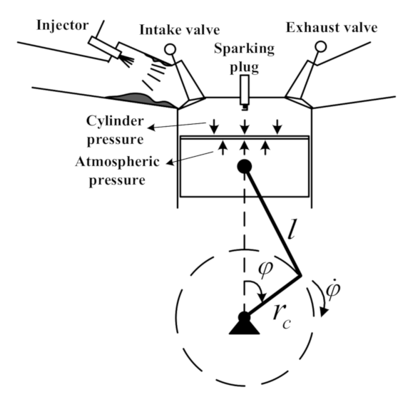
2.1.1. Engine Thermodynamic Model in the Cylinder

The general formula of the engine working process was obtained using the first thermodynamic formula [31,32]. In the i-th cylinder (I = 1,2,3,4), the cylinder pressure P c y l , i φ can be obtained by Formula (1):
d T t e m p d φ = 1 m u T t e m p ( d Q B d φ + d Q w d φ P c y l , i φ d V c y l d φ + d m s c d φ h s c     + d m e d φ h e u d m d φ m u λ d λ d φ ) d m d φ = d m B d φ + d m s c d φ + d m e d φ P c y l , i φ V c y l φ = m φ R T t e m p φ
here,
V φ = V s 2 2 ε c 1 + 1 cos φ + 1 λ s 1 1 λ s 2 sin 2 φ
where T t e m p is engine cylinder temperature; m is the gas mass in the engine cylinder; φ is the crankshaft rotation angular displacement; u is the specific thermodynamic energy; V c y l is the engine’s instantaneous work volume; λ is the engine excess air ratio; R is a gas constant value; h is the specific enthalpy; V s is the engine’s physical work volume; ε c is the engine compression ratio, and λ s is the engine crank-link ratio. Q is the engine exchange heat of the cylinder gas. Subscript s c represents the gas entering the engine cylinder. Subscript e represents the gas entering the engine cylinder through the exhaust; subscript B represents the heat released from gasoline combustion; subscript w is the heat exchange between the wall and the outside; λ s = r c / l , l is the engine-connecting rod length; and r c is engine crankshaft radius.

2.1.2. Engine Pulsating Torque Model

For a gasoline engine with four cylinders, the dynamic torque T E R T of the engine in front of the engine flywheel can be expressed as the sum of the torque of each cylinder with a difference of 180°, that is, [20,26],
T E R T = i T c y l , i = i T P i + T I i + T F
where T c y l , i is the dynamic torque of a single cylinder; T P i is the pulsation torque of the cylinder pressure; T I i is the engine inertia torque; and T F is the engine friction torque.

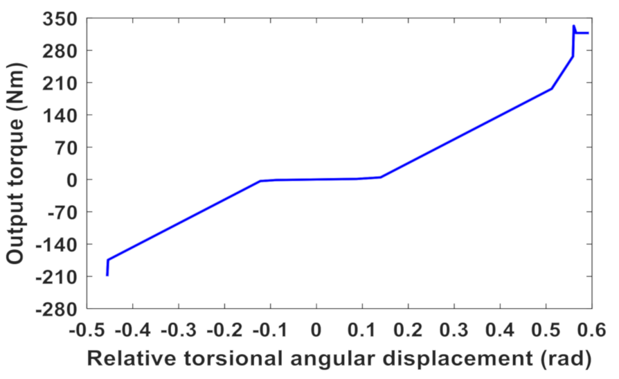
2.2. Model of Torsional Damper Spring

According to the torsional stiffness characteristic curve (as shown in Figure 3) and the hysteresis damping moment of the torsional damper, the torsional damper model is established by using the table-lookup method.

2.3. Motor Dynamic Model

Considering the battery SOC and the characteristics of the two motors, a three-phase permanent magnet synchronous motor (PMSM) with sinusoidal back electromotive force is built in the rotor reference frame (q-d frame). The PMSM is connected to the battery through a DC/DC converter and a three-phase inverter [30], and the battery provides energy to the motor. The basic electromagnetic torque model of the motor is as follows [26,33]:
T M G = 1.5 p s [ λ a i q + ( L d L q ) i d i q ]
where, p s is the number of pole pairs; λ a is the amplitude of induced magnetic flux; L q and L d are the inductance of axis q and axis d, respectively; and i q and i d are the current of axis q and axis d, respectively.

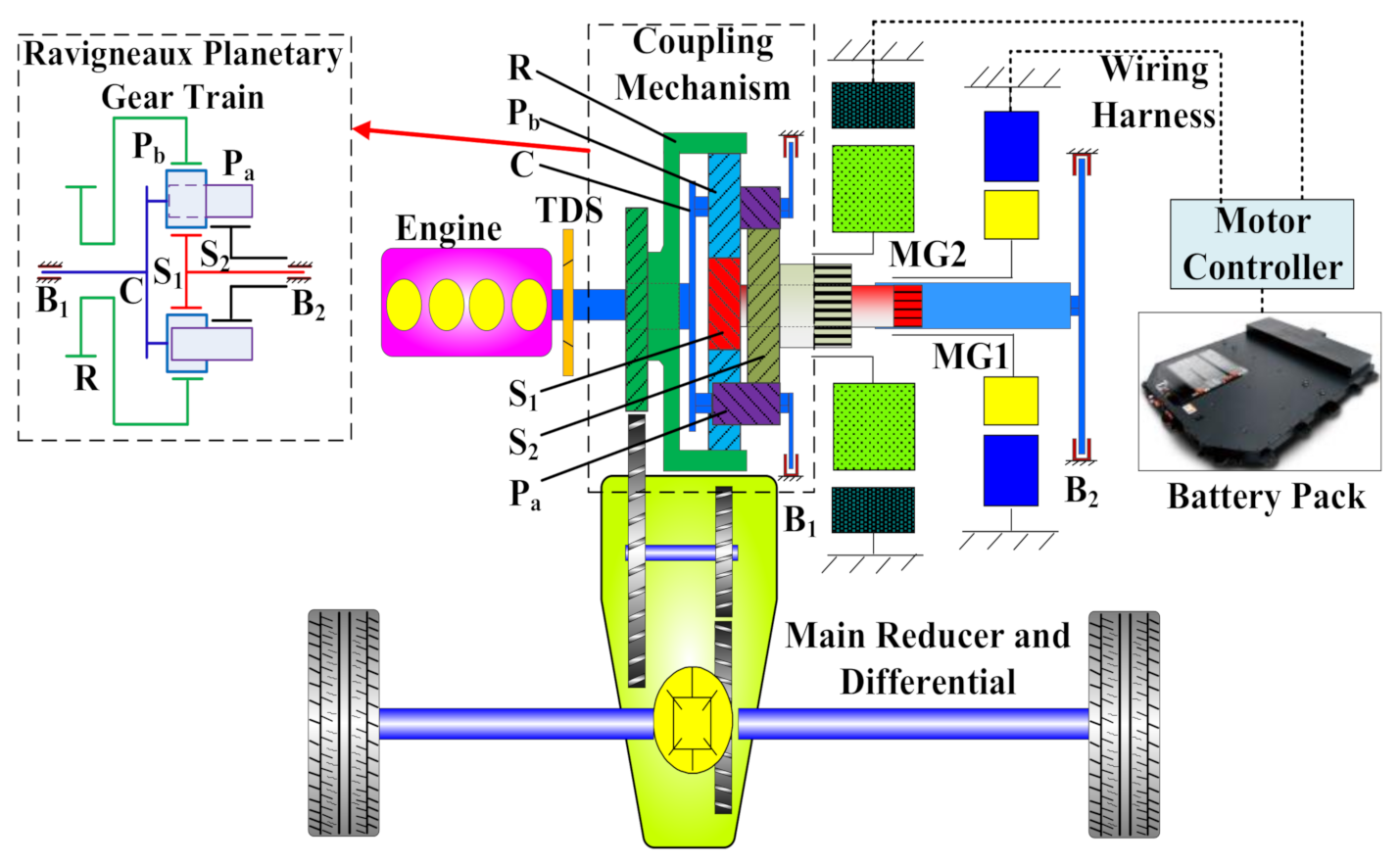
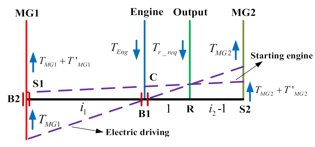
2.4. Coupling Mechanism Modeling

For the power-split transmission, the motion equations of the compound planetary gear model are given using the centralized mass method [20,34] as follows:
I s 1 θ ¨ s 1 = T s 1 + n = 1 N F y s 1 b n r s 1
I s 2 θ ¨ s 2 = T s 2 + n = 1 N F y s 2 a n r s 2
I ce θ ¨ C = T C + n = 1 N F y s 2 a n cos α s 2 r C + n = 1 N F y s 1 b n cos α s 1 r C     n = 1 N F y R b n cos α R r C
I R θ ¨ R = n = 1 N F y R b n r R T T I
I a θ ¨ a n c = F y a n b n r a F y s 2 a n r a
I b θ ¨ b n c = F y a n b n r b F y R b n r b F y s 1 b n r b
where I is the inertia of the component; r is the base circle radius of gear; α is the meshing angle of a pair of gears; θ is the gear rotation angle; T is the input torque; and F y is the meshing force between gears [34]. Furthermore, a and b are the rear and front row planetary gears of the compound planetary gears, and T T I is the equivalent TI shaft torque in Figure 3. N ( n ) is the number of planetary gears, and I c e = I c + N I a + N I b . Note that the vehicle equivalent inertia to the common gear ring is taken into account in IR.

2.5. Brake Dynamic Model

The brake model has three working states: disengagement, sliding, and engagement [26]. The transmission torque T B of the brake is expressed as
T B = 0 ,   d i s e n g a g e m e n t μ s l r B P B P 0 A B N B sgn θ ˙ c _ g ,   s l i d i n g μ s t r B P B P 0 A B N B   μ s t r B P B P 0 A B N B ,   e n g a g e m e n t
where θ ˙ c _ g is the velocity of the planetary frame; μ s l is the sliding friction coefficient of the friction plate; μ s t is the static friction coefficient of the friction plate; N B is the friction disk number; r B is the friction radius of the friction plate; A B is the friction area; P B is the oil pressure; and P 0 is the pre-filled oil pressure.

2.6. Vehicle Dynamic Model in Longitudinal Direction

The longitudinal dynamic driving model of the vehicle is expressed as
T ˙ T I = k T I θ ˙ R θ ˙ L + C T I θ ¨ R θ ¨ L
m v V ˙ x = T T I i 0 / r v T f / r v T f = r v ( 0.5 C d ρ A V x 2 sgn V x   + m v g f cos β + m v g sin β )
where C T I and k T I are the damping and stiffness at the TI shaft in Figure 8; θ ˙ R is the ring speed; θ ˙ L is the rotation speed at the point B in Figure 8; θ ¨ R is the ring angular acceleration; θ ¨ L is the rotation acceleration of point B; i 0 is the speed ratio of the main reducer; r v is the radius of the wheel; g is the acceleration of gravity; m v is the equivalent mass of the vehicle; V x is the speed of the car; f is the rolling resistance coefficient; β is the road slope; T f is the wheel load torque; C d is the coefficient of air resistance; ρ is the density of air; and A is the windward area of the vehicle.

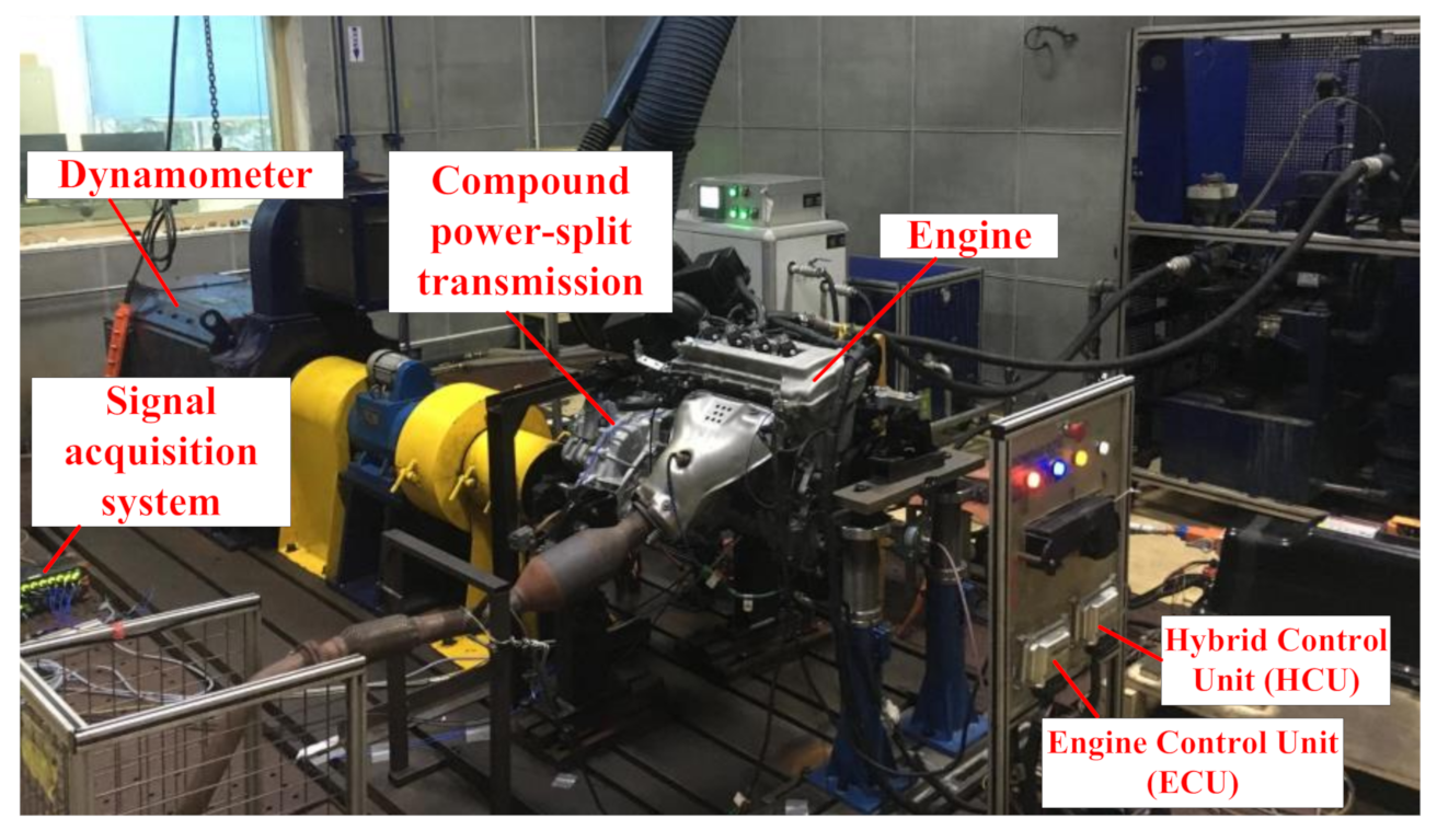
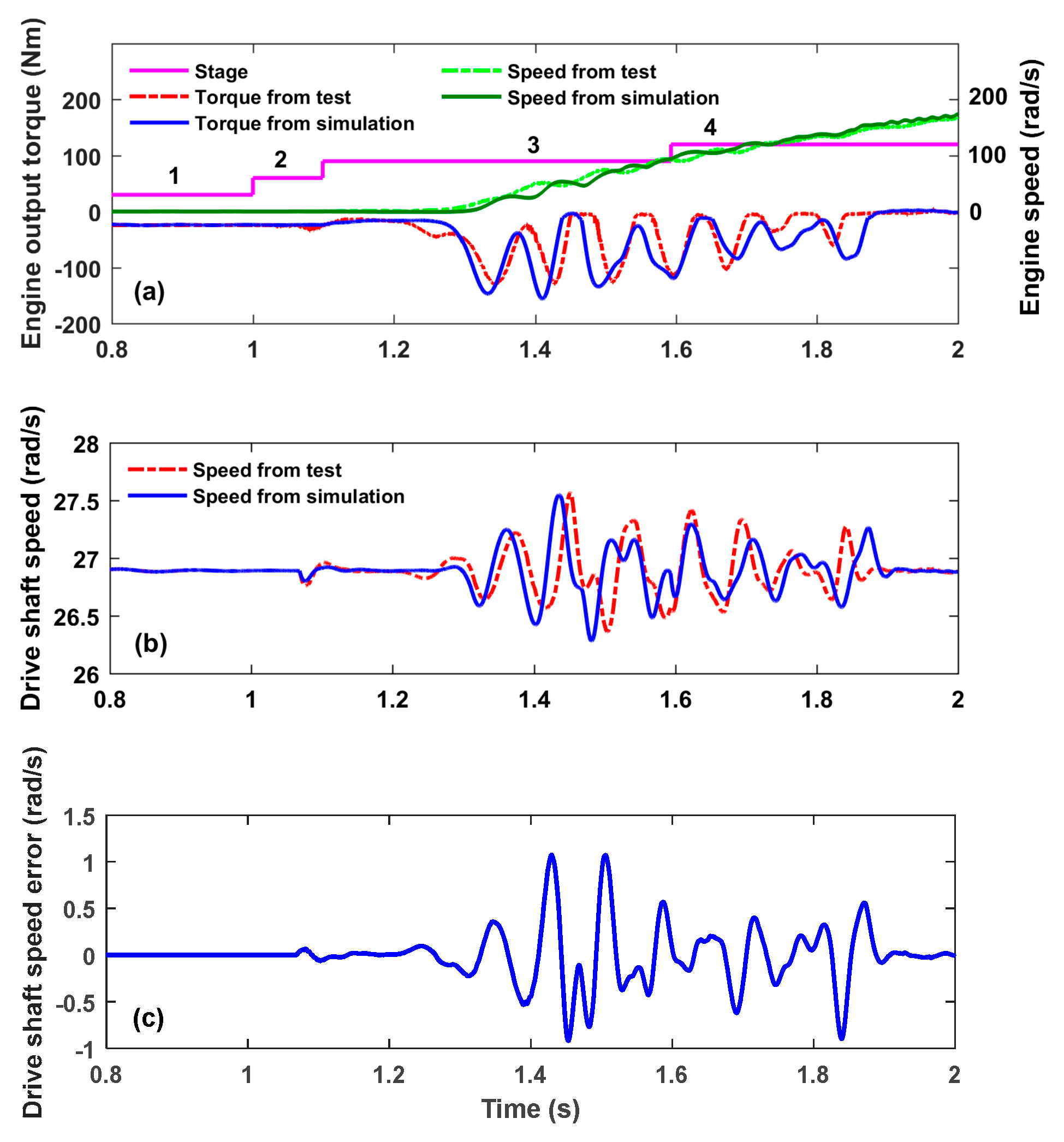
2.7. Validation of PS-PHEV Powertrain Model

A PHEV test bench was built to verify the validity of the established model as shown in Figure 4. The engine startup process is tested when the dynamometer is running at 27 rad/s. As shown in Figure 5a, the MT process with the engine startup includes four work stages: (1) pure electric stage with B1 locked, (2) pure electric stage with B1 opened, (3) a motoring stage before engine ignition, and (4) a hybrid driving stage after engine ignition. The engine shaft torque and speed obtained by simulation are basically consistent with the test results. As shown in Figure 5b, the driving shaft torque and speed obtained by simulation are basically consistent with the test results. Figure 5c shows the error between the simulation results and the test results of the drive shaft speed. It can be seen from these results that the maximum error of the drive shaft speed is less than 1.2 rad/s, and the relative error of the driveshaft speed is less than 5%. By comparing and analyzing the simulation results with the test results, the established model can basically reflect response characteristics of the power transmission in the mode switching process. The powertrain system model lays the foundation for the subsequent evaluation of the effectiveness of the proposed dynamic torque-coordinated control method. The main PS-PHEV parameters are listed in Table 1.

3. Dynamic Analysis and Problem Description during Engine Starting Process

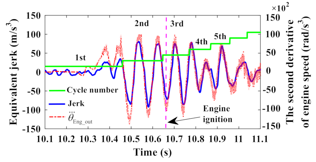
3.1. Dynamic Analysis during Engine Starting Process

Figure 6 shows the lever diagram in the engine startup process. The black solid line in this figure is the lever balance line. The speed on the balance line is defined as zero. The speed below the balance line is negative, and the speed above the balance line is positive. The up arrow = indicates that the torque is positive, and the down arrow indicates that the torque is negative.
As shown in Figure 6, in the process of engine starting, MG1 torque pluses T M G 1 , to start the engine and bring the engine to its ignition speed. The output power of MG1 is negative, indicating that MG1 is in the power generation state. MG2 adopts a compensation torque T M G 2 , on the basis of T M G 2 to ensure the vehicle runs forward. Ignored were the stiffness-damping elastic effect on the MG1 shaft, MG2 shaft, engine output shaft, drive shaft, as well as the dynamic meshing force and efficiency loss between gears. Based on the lever method [35], the torques of MG1 and MG2 during the engine startup can be expressed as follows:
T M G 1 = ( i 2 1 ) T r _ r e g + i 2 ( T E n g ( I E n g + I c ) θ ¨ Eng _ des ) i 1 i 2         + ( I s 1 + I M G 1 ) ( i 0 i 1 θ ¨ W H + ( 1 i 1 ) θ ¨ Eng _ des ) T M G 2 = ( i 1 1 ) T r _ r e g + i 1 ( T E n g ( I E n g + I c ) θ ¨ Eng _ des ) i 2 i 1         + ( I s 1 + I M G 2 ) ( i 0 i 2 θ ¨ W H + ( 1 i 2 ) θ ¨ Eng _ des )
where T M G 1 is the MG1 torque; T M G 2 is the MG2 torque; T r _ r e q is the ring torque required; T E n g is the engine torque; I M G 1 is the moment of inertia of MG1; and I M G 2 is the moment of inertia of MG2. Additionally, I S 1 is the moment of inertia of the little sun wheel; I S 2 is the moment of inertia of the big sun wheel; i 0 is the speed ratio of the main reducer; θ ¨ W H is the angular acceleration of the wheel; I E n g is the moment of inertia of the engine. I C is the moment of inertia of the planetary frame; θ ¨ Eng _ des is the engine acceleration; i 1 is the front-row speed ratio; and i 2 is the rear-row speed ratio.

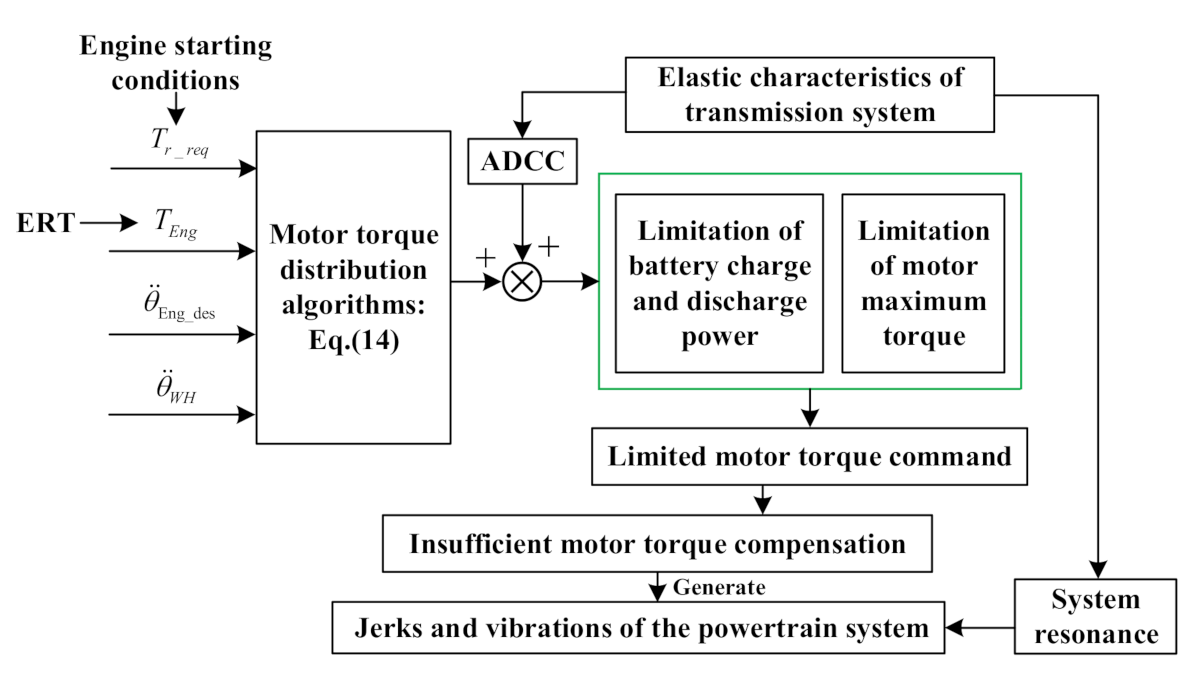
3.2. Problem Description during Engine Starting Process

Fuel economy can be effectively improved using the switching working modes for a PHEV [36,37]. However, as shown in Figure 7 for the compound PS-PHEV, during the mode switching process, which includes the engine start-up process, the distribution torque command of the two motors can be obtained by the superposition calculation of the motor distribution torque from Equation (14) and the active damping compensation control (ADCC) torques [19,20]. However, in some engine starting conditions, due to the ERT, the elastic characteristics of the transmission system, limitations of battery power, and limitations of motor maximum torque, the torques of the two motors, are limited, which make them unable to effectively compensate or offset the fluctuating torque of the powertrain. These factors will result in obvious transmission jerks and resonance, which will eventually make driving less comfortable and reduce the service life of the vehicle.
Therefore, in view of the above problem, it is necessary to design a dynamic torque-coordinated control that considers engine starting conditions to further reduce the system shocks and vibrations.

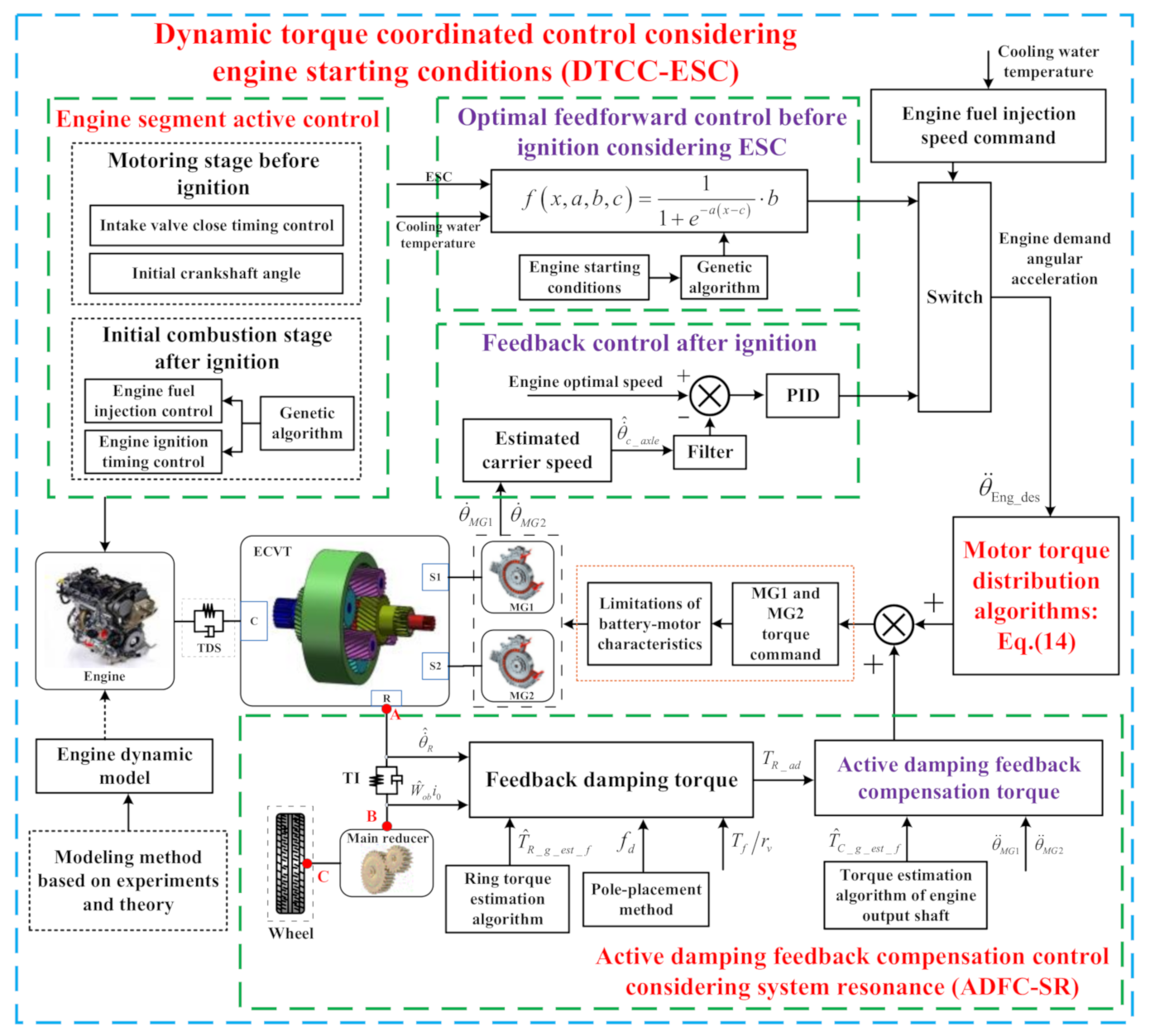
4. Design of Dynamic Torque-Coordinated Control That Considers Engine Starting Conditions

To solve the problem of insufficient motor torque compensation under some engine starting conditions, as illustrated in Figure 8, a dynamic torque-coordinated control method that takes into account engine starting conditions (DTCC-ESC) is proposed in this paper for the first time. The DTCC-ESC mainly includes three parts: the engine segment active control, the feedforward and feedback control of engine starting, and the active damping feedback compensation control for the resonance of the transmission system.
(1)
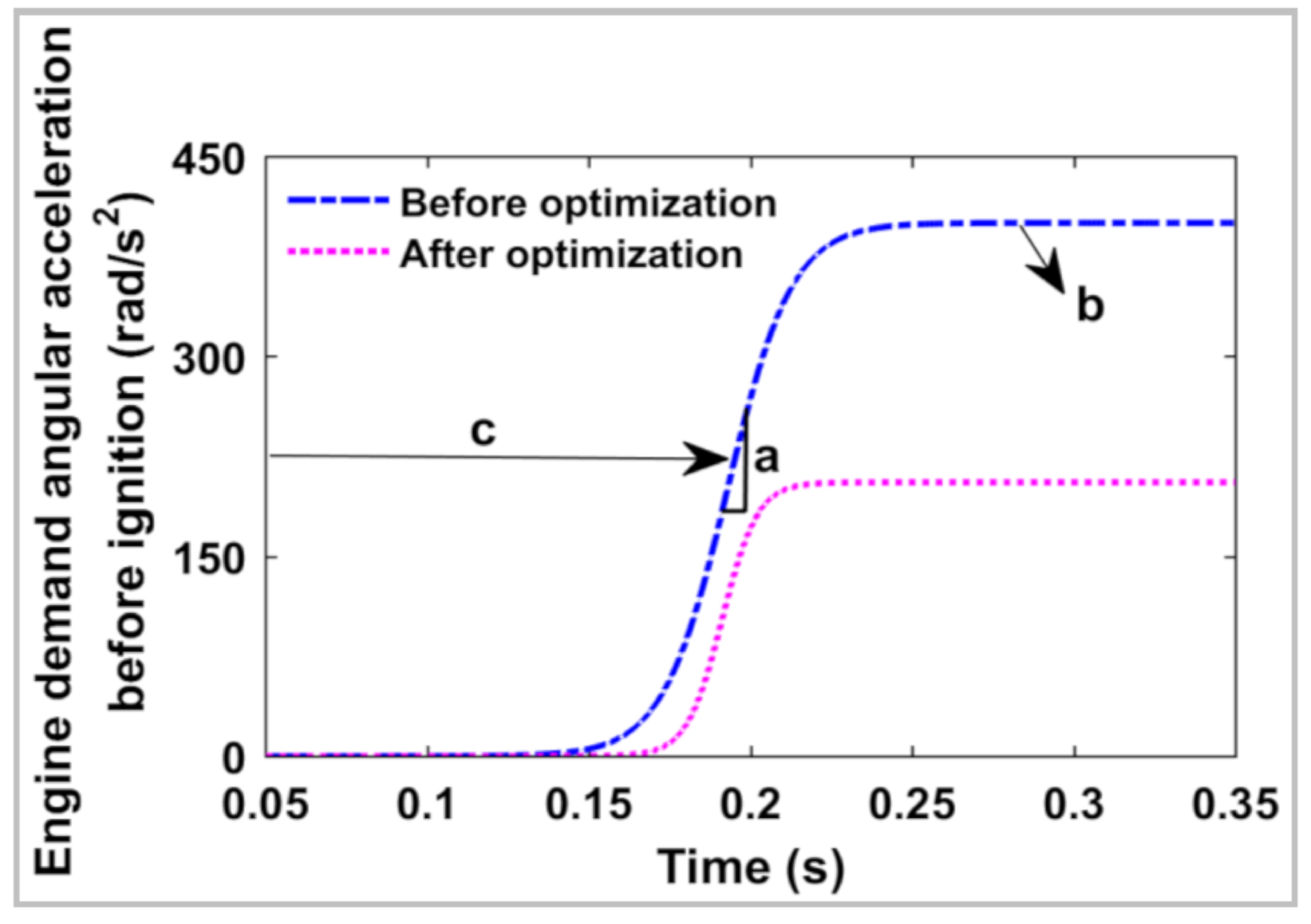
The engine segment active control, also known as the engine transient torque control before and after the engine ignition, is used to reduce the impact of the ERT on system shocks and vibrations in the engine startup from the perspective of the engine power source. Regarding this engine segment active control: before ignition, the inputs of control are the engine’s intake valve close timing (IVCT) and initial crankshaft angle (ICA); after ignition, the inputs of control are fuel injection and engine ignition timing optimized by a genetic algorithm based on the engine working cycle. The output of the control is the engine output torque.
(2)
Feedforward and feedback control of engine starting is mainly realized by solving the motor torque distribution algorithm from Equation (14) through different engine demand angular accelerations before and after ignition. For the feedforward and feedback control of the engine startup, the inputs of control are a) the required angular acceleration of the engine based on the engine starting conditions before ignition and b) the required angular acceleration of the engine based on the engine optimal target speed after ignition. The outputs of control are the distributed torques of the two motors based on Equation (14).
(3)
The active damping feedback compensation control for the system resonance (ADFC-SR) is adopted to restrain the vibration of the transmission system. The inputs of the ADFC-SR are the estimated ring speed and torque, the estimated engine output shaft torque, and the estimated wheel speed. Its outputs are the active damping feedback compensation control torques from Equation (22).

4.1. Engine Segment Active Control

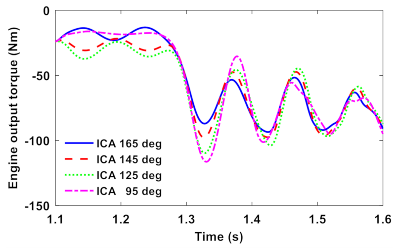
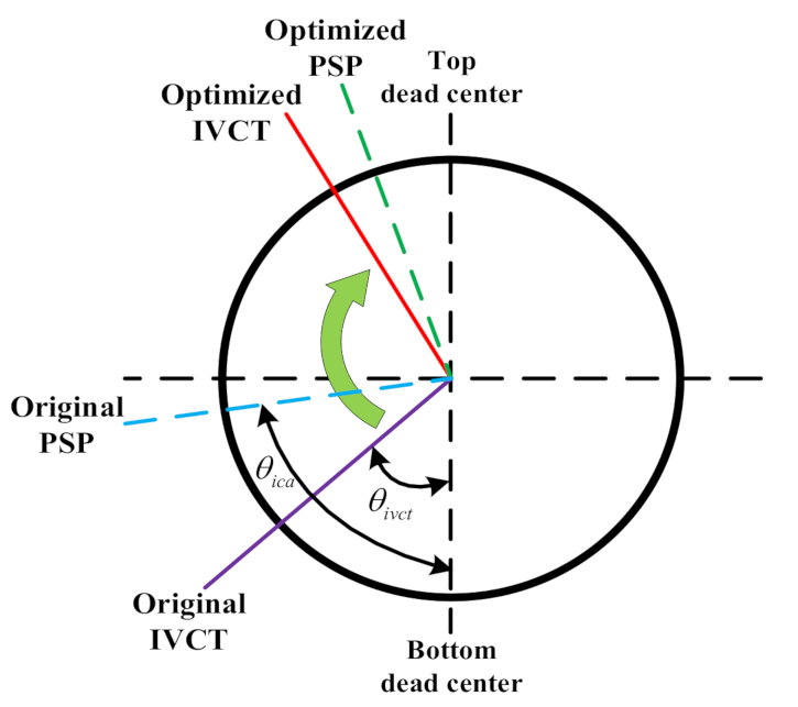
4.1.1. Intake Valve Close Timing Control before Ignition

According to the engine thermodynamic Equation (1), since the temperature and gas constant in the cylinder are little changed before ignition, the engine’s instantaneous cylinder pressure P c y l , i φ is mainly related to the instantaneous cylinder volume V φ and air mass m φ in the cylinder. The intake valve close timing (IVCT) of the engine can change the initial volume V i n i t i a l φ and gas mass m φ of the closed cylinder in the process of engine intake and compression, and the initial crankshaft angle (ICA) can change the initial volume V i n i t i a l φ and gas mass m φ of the closed cylinder in the compression stage of the first working cycle of the engine startup. Therefore, the IVCT and ICA can directly change the cylinder pressure in the engine compression stage. Combining Equation (3), the relationship between engine ripple torque T E R T and IVCT and ICA can be obtained.
T E R T θ i v c t , θ i c a = i T P i θ i v c t , θ i c a + T I i + T F θ i c a
where θ i v c t is the angle between IVCT and bottom dead center; θ i c a is the ICA between the piston stop position (PSP) and the bottom dead center in the engine compression stage, as shown in Figure 9.
As shown in Figure 10, before engine ignition, when θ i c a is 85° and the cooling water temperature is 25 °C, the engine-output torque decreases significantly with the increase in IVCT. This is because the actual air volume in the cylinder decreases with the increase in IVCT, resulting in a significant reduction of engine cylinder pressure ripple torque T P i θ i v c t , θ i c a . Therefore, the engine output ripple torques can be significantly reduced by delaying IVCT. In Figure 11, it is observed that a different ICA has an obvious impact on engine output ripple torque when θ i v c t is 150° and the cooling water temperature is 25 °C. When the ICA is larger (closer to the top dead center), the engine’s output shaft ripple torque decreases significantly. This is mainly because the closer the PSP is to top dead center, the smaller the initial transient cylinder pressure of the first working cycle in the compression stage will be.
Therefore, according to the influence of the IVCT and ICA on engine output torque, the original IVCT and ICA are optimized by θ i v c t = 150 deg and θ i c a = 165 deg to minimize the engine output ripple torque to reduce the impact of the ERT on the system shocks and vibrations before ignition.

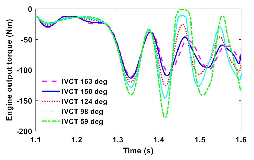
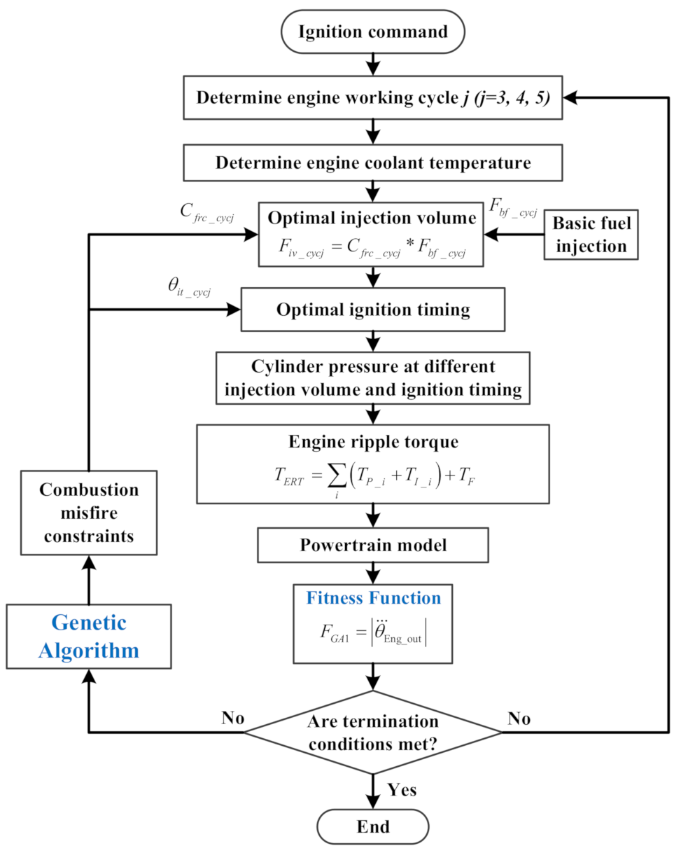
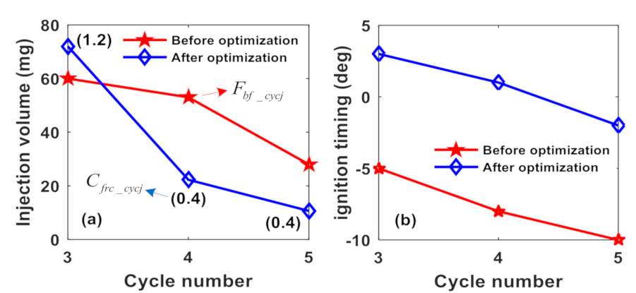
4.1.2. Controls of Engine Fuel Injection and Ignition Timing

According to the bench test results, the equivalent jerk based on an engine working cycle number is obtained as shown in Figure 12. Note that the vehicle jerk is the second derivative of the vehicle speed [38] and the engine crankshaft angle every 720 deg of rotation is an engine working cycle. It can be seen from this figure that the transmission system has obvious jerks during engine starting. For the jerks after ignition, it is found that the equivalent jerk of the first three working cycles (3rd, 4th and 5th) after ignition is greater than that of subsequent engine working cycles. Therefore, this part is mainly focused on reducing the shocks and vibrations of the first three working cycles after ignition. Moreover, as shown in Figure 12, we can see that the second derivative of engine speed, θ Eng _ out has a similar fluctuation pattern with an equivalent jerk, which shows that the θ Eng _ out can indirectly reflect the fluctuation phenomenon of a vehicle jerk. This provides a basis for choosing an objective function F G A 1 optimized by a genetic algorithm.
Since the running time of the first three working cycles after ignition is about 300 ms, it is necessary to realize the transient torque change by means of fast engine response control. Although the engine output torque can be greatly adjusted by the throttle control method, its control response time is longer. Compared to engine throttle control, fuel injection and ignition controls have a faster control effect on engine transient torque [39]. Therefore, controls of fuel injection and ignition timing based on an engine working cycle will be used to rapidly change engine output torque to reduce jerks of the powertrain system during initial engine combustion, especially the first three working cycles after engine ignition in stage 4.
As shown in Figure 13, in this paper, according to the engine working cycle and cooling water temperature of engine, the engine fuel injection F i v _ c y c j and ignition timing θ i t _ c y c j of the first three working cycles after engine ignition are optimized by using a genetic algorithm [40]. Since the main purpose of this paper is to reduce shocks in mode switching, which that includes engine starting, the effect of emissions will not be considered as a subject of interest.
The injection volume F i v _ c y c j of the first three working cycles after ignition is expressed as follows:
F i v _ c y c j = C f r c _ c y c j F b f _ c y c j
where C f r c _ c y c j and F b f _ c y c j are the fuel-ratio coefficient and basic fuel injection at the jth working cycle (j = 3, 4, 5), respectively.
In the initial combustion of an engine startup, a too large or too small ignition angle will lead to a fuel injection combustion misfire [41]. Therefore, in practice, the engine ignition angle and fuel injection need to be limited to a certain range to ensure a smooth start. The combustion misfire constraints of the engine from engine experimental data are as follows.
C f r c _ c y c 3 0.9   1.6 C f r c _ c y c 4 0.4   1.6 C f r c _ c y c 5 0.2   1.2 θ i t _ c y c 3 20   5 θ i t _ c y c 4 25   10 θ i t _ c y c 5 30   15
where the ignition timing at the top dead point is defined as zero. The negative θ i t _ c y c j is the ignition advance angle, and the positive θ i t _ c y c j is the ignition delay angle.
Since the second derivative of engine speed, θ Eng _ out can reflect the fluctuation of a vehicle jerk, the absolute value of θ Eng _ out is used as the fitness function F G A 1 of the genetic algorithm:
F G A 1 = θ Eng _ out
The optimization is achieved in steps illustrated in the Figure 13, which are explained as follows:
Step 1: In accordance with the established powertrain model, the engine system enters the working cycle j (j = 3, 4, 5) after receiving the ignition command.
Step 2: Under the engine coolant temperature and combustion misfire constraints of the engine, the genetic algorithm [40] automatically initializes the fuel ratio coefficient C f r c _ c y c j and ignition timing θ i t _ c y c j to obtain the initial transient cylinder pressure, and then calculates the engine ripple torque.
Step 3: Using the powertrain simulation model with the obtained ERT, the fitness function F G A 1 is then calculated.
Step 4: The termination condition of genetic algorithm iteration is then checked. If it is completed, the optimization of the first three working cycles after ignition will be carried out in sequence according to the above three steps.
When the cooling water temperature is set to 25 °C, results before and after optimization of the first three working cycles after ignition are obtained by the genetic algorithm, as shown in Figure 14 and Figure 15. From Figure 14a, we can see that in the 4th and 5th engine working cycles, the injection volumes are reduced to 40% of the basic fuel injection. In Figure 14b, the ignition timings in these three working cycles are all delayed. As observed in Figure 15, the amplitude of θ Eng _ out is reduced significantly by the optimization, which can reflect the reduction of the vehicle jerks. In addition, the fuel injection volume of the third working cycle (that is the first working cycle after ignition) in Figure 14a is 20% higher than it was before optimization. This is mainly because the firing reliability can be improved by properly increasing the injection volume of the first working cycle after a cold-start ignition, and enough oil film can be formed in the engine intake port. However, due to the delay of ignition timing, the θ Eng _ out is still less than the value before optimization in Figure 15 in the 3rd engine working cycle.

4.2. Feedforward and Feedback Controls of Engine Starting

According to Equation (14), the required acceleration of the engine θ ¨ Eng _ req is an important control variable in the engine starting process. As shown in Figure 8, feedforward and feedback controls of engine starting are mainly realized by solving the motor torque distribution algorithm, Equation (14), based on different demand-angular acceleration before and after engine ignition.

4.2.1. Feedforward Control before Ignition

As shown in Figure 8, to start the engine reliably and smoothly before ignition, the feedforward control method before ignition was adopted. Firstly, the “S-curve” function f x , a , b , c from Equation (19) was taken as the required acceleration of the engine, θ ¨ Eng _ des . Then, the f x , a , b , c was brought into Equation (14) to obtain the two motor-distribution torques, which are required by the feedforward control before ignition.
In the feedforward control, under the given cooling water temperature and different engine starting conditions, taking the absolute value of vehicle jerk as the fitness function F G A 2 , the genetic algorithm was used to optimize a, b and c to obtain the optimal “S-curve” function (the optimal engine demand-angular acceleration) under different engine starting conditions before engine ignition.
The S-curve function f x , a , b , c is defined as follows.
θ ¨ Eng _ des = f x , a , b , c = 1 1 + e a x c b
where a, b and c are the parameters of the θ ¨ Eng _ des .
The jerk absolute value was used as the fitness function F G A 2 of the genetic algorithm:
F G A 2 = j e r k = V ¨ x
where j e r k is the vehicle jerk.

4.2.2. Feedback Control after Ignition

In order to make the actual engine speed follow the engine optimal target speed in time after ignition, the engine angular acceleration required by feedback control will be obtained by a PID controller (p = 5, I = 1 and d = 0.4). As shown in Figure 8, the inputs of the PID controller were engine optimal speed and the estimated carrier speed. The estimated carrier speed θ ˙ ^ c _ a x l e is expressed as follows:
θ ˙ ^ c _ a x l e = i 2 θ ˙ M G 1 i 1 θ ˙ M G 2 i 2 i 1
where θ ˙ M G 1 and θ ˙ M G 2 are the speeds of MG1 and MG2, respectively.

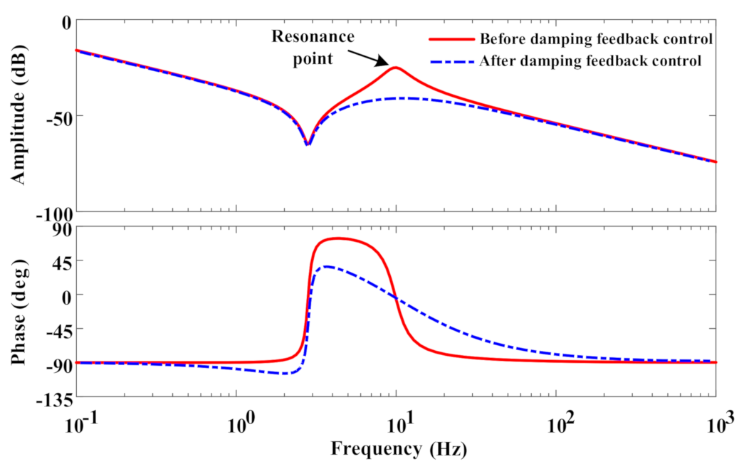
4.3. Active Damping Feedback Compensation Control Considering System Resonance

4.3.1. Active Damping Feedback Compensation Torques

The ADFC torques of the two motors ( T M G 1 _ D a m p and T M G 2 _ D a m p ) can be obtained by the equivalent lever method [40] in Figure 6, which compensates for the torque fluctuations transmitted to the wheels.
T M G 1 _ D a m p = i 2 1 i 1 i 2 ( T R _ a d + I R 1 i 1 θ ¨ M G 2 1 i 2 θ ¨ M G 1 i 2 i 1 ) + i 2 i 1 i 2 T ^ c _ g _ est _ f + ( I s 1 + I M G 1 ) θ ¨ M G 1 T M G 2 _ D a m p = i 2 1 i 1 i 2 ( T R _ a d + I R 1 i 1 θ ¨ M G 2 1 i 2 θ ¨ M G 1 i 2 i 1 ) + i 1 i 2 i 1 T ^ c _ g _ est _ f + ( I s 2 + I M G 2 ) θ ¨ M G 2
where T R _ a d is the feedback damping torque and I R is the ring inertia. In addition, T ^ c _ g _ est _ f was obtained by Kalman filtering of the estimated carrier torque T ^ c _ g _ est ; θ ¨ M G 1 is the MG1 acceleration; and θ ¨ M G 2 is the MG2 acceleration.
The formula of the estimated carrier torque T ^ c _ g _ est (engine output shaft torque) is obtained as follows:
T ^ c _ g _ est = i 1 1 T M G 1 + i 2 1 T M G 2 i 1 1 I s 1 + I M G 1 θ ¨ M G 1        i 2 1 I s 2 + I M G 2 θ ¨ M G 2
To reduce the resonance of the transmission system itself and the torque fluctuations transmitted to the wheel, the feedback damping torque T R _ a d is expressed as
T R _ a d = T ^ R _ g _ e s t _ f f d W ^ o b i 0 θ ˙ ^ R T f / r v T P I D ( W ^ o b i 0 , θ ˙ ^ R )
where T ^ R _ g _ e s t _ f is obtained by Kalman filtering of the estimated ring torque T ^ R _ g _ e s t ; f d is the feedback gain damping coefficient; W ^ o b is the estimated wheel speed; θ ˙ ^ R is the estimated speed at ring gear; and T P I D ( W ^ o b i 0 , θ ˙ ^ R ) is the adjustment of the speed error at the gear ring, which is from a PID controller whose inputs are W ^ o b i 0 and θ ˙ ^ R .
The estimated ring torque T ^ R _ g _ e s t is determined as follows:
T ^ R _ g _ e s t = i 1 T M G 1 i 2 T M G 2 + i 1 I s 1 + I M G 1 θ ¨ M G 1       + i 2 I s 2 + I M G 2 θ ¨ M G 2
The estimated speed at ring gear, θ ˙ ^ R , can be obtained as follows:
θ ˙ ^ R = 1 i 1 θ ˙ M G 2 1 i 2 θ ˙ M G 1 i 2 i 1

4.3.2. Wheel Speed Estimation

A wheel-speed observer is designed to obtain an accurate, real-time wheel speed W ^ o b . In the following formula, X and U are selected as the state variables and control variables, respectively.
X = θ ˙ L θ ˙ R θ L θ R T
U = T L T ^ R _ g _ e s t _ f T
The discretization state equation is expressed as follows:
X ^ k + 1 = M 0 0 I 1 C K I 0 X ^ k       + M 0 0 I 1 N 0 U k W ^ o b k = I 4 × 4 1 , 1 X ^ k / i 0
with
M = I L 0 0 I R , N = 1 0 0 1 ,
C = C T I C T I C T I C T I , and K = k T I k T I k T I k T I , where X ^ is the estimation state variables; I is the unit matrix; and k is the sample number.

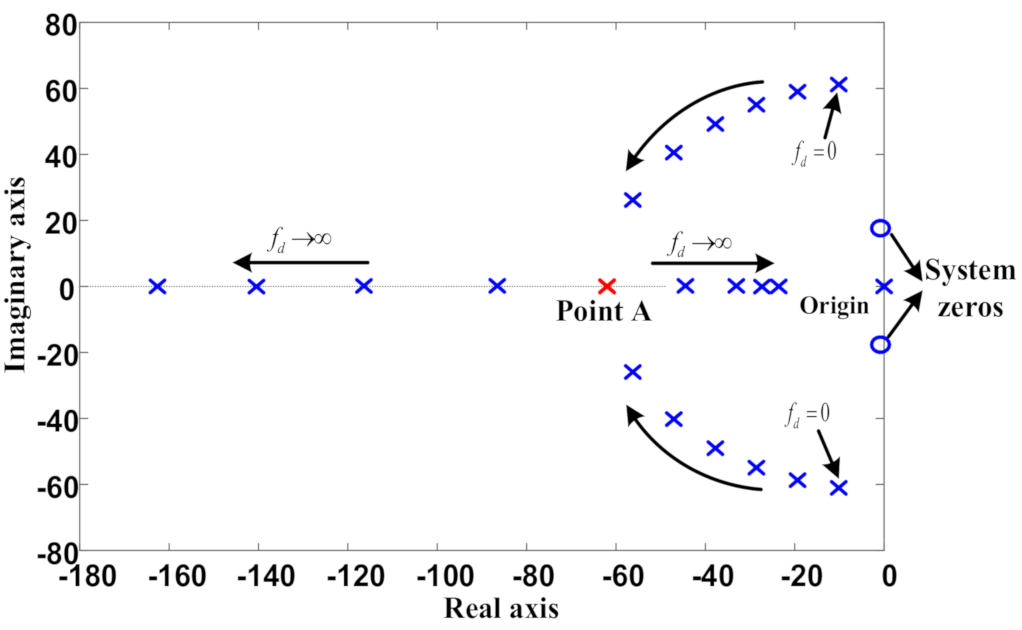
4.3.3. Determination of Feedback Gain Damping Coefficient

Based on the simplified spring-mass model between point A and point B in Figure 8, the system transfer function G R ( s ) from point A to point B can be obtained as follows:
G R ( s ) = 1 I R s 2 + c T I I R I L s + k T I I R I L s s 2 + c T I ( 1 I R + 1 I L ) s + k T I ( 1 I R + 1 I L )
where I R is the equivalent ring inertia; I L is the equivalent moment of inertia at point B in Figure 8; and s is the Laplace operator.
Figure 16 is the Bode diagram of the system before and after the damping feedback control. It shows the amplitude-frequency and phase-frequency characteristics of the transfer function G R ( s ) . From the solid red line before the damping feedback control, it could be seen that the transmission system resonates at 9.86 Hz. To reduce the resonance of the powertrain system further, the speed error of the output shaft was controlled by the damping feedback method, which is defined as
T = f d W ^ o b i 0 θ ˙ ^ R
By introducing the feedback gain damping coefficient f d into Equation (32), the transmission system transfer function from point A to point B under closed-loop control can be obtained again as follows:
G R ( s ) = 1 I R s 2 + c T I I R I L s + k T I I R I L s s 2 + c T I ( 1 I R + 1 I L + f d I R ) s + k T I ( 1 I R + 1 I L )
Figure 17 is a zero-pole distribution diagram based on the root locus, which is used to allocate the poles of the system. The transfer function G R ( s ) has three poles before the damping feedback control, one of which is at the origin of Figure 17; the other two are a pair of conjugate complex poles with fd = 0. Under the damping feedback closed-loop control, with the increase of fd, the two poles without origin will gradually approach the real axis and become two double roots at point A in Figure 17. When fd continues to increase, one pole of the system moves to the left and the other pole moves to the right, and the response time of the system will increase. Based on this, in this paper, the two poles are located at the same point A in Figure 17, and the feedback gain damping coefficient fd is 5.6228. In addition, the dotted line after the damping feedback control in Figure 16 is the Bode diagram result when fd = 5.6228. The feedback gain-damping control optimized by the zero-pole distribution method can reduce the resonance peak of the transmission system better.

5. Simulations and Assessments

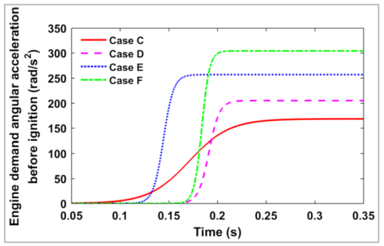
5.1. Simulation Conditions

To verify the effectiveness of the proposed DTCC-ESC method more comprehensively, six typical engine starting conditions (Case A, Case B, …, Case F), as shown in Figure 18 and Table 2, were set as simulation conditions during mode switching that included engine starting. Figure 18 shows the required ring torque converted from the acceleration pedal position (APP) and vehicle speed in EV mode. Table 2 further shows other engine-starting conditions, which include engine coolant temperature, battery temperature, and battery SOC. Note that the influence of SOC, temperature, and other factors on the dynamic response characteristics of the vehicle during engine starting can be referred to the literature [42].

5.2. Comparative Analysis of Different Control Methods

In order to verify the effectiveness of the proposed DTCC-ESC method, as shown in Table 3, the active damping compensation control (ADCC) method, the active damping compensation control with engine active control (ADCC-EAC) method, and the DTCC-ESC method proposed in this paper were selected for simulation and comparative analysis on the established compound power-split PHEV model. In addition, taking point D of the engine starting condition as an example, the simulation results were analyzed in detail, and then six typical engine-starting condition points in Figure 18 were taken as examples to analyze the vehicle jerks under different engine starting conditions.

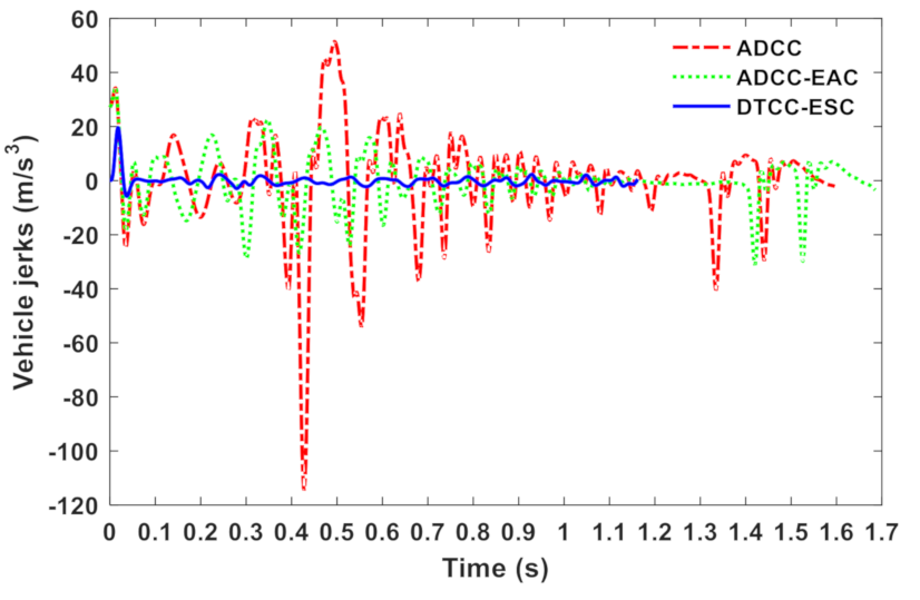
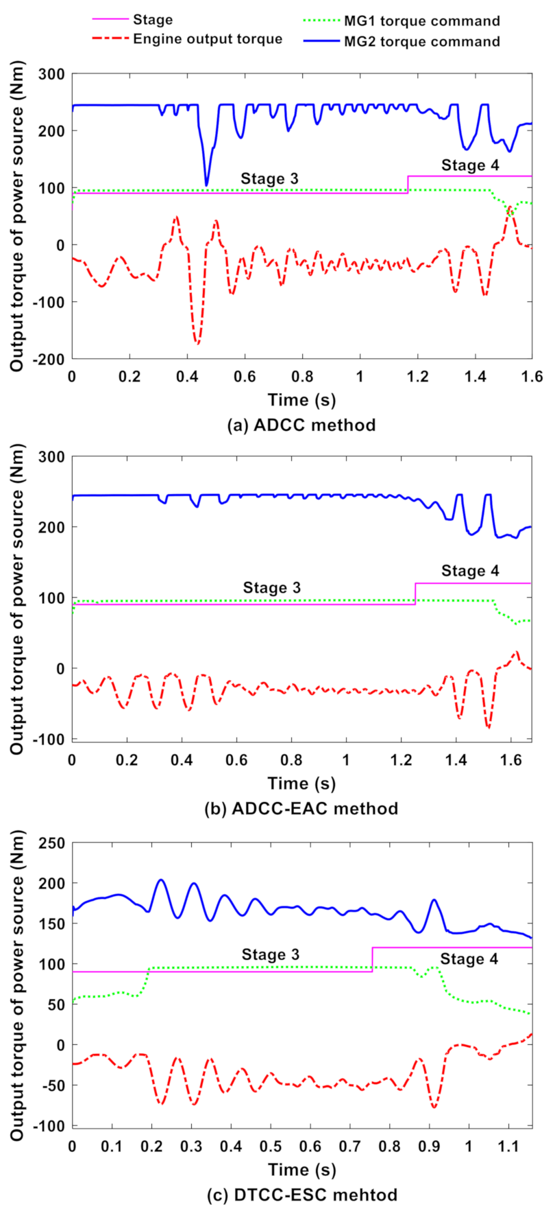
5.2.1. Results of Three Control Methods under Case D

Figure 19 shows the results of engine-demand angular acceleration before and after optimization under engine-starting condition point D. It can be seen that the amplitude of the optimized demand-angle acceleration of the engine is smaller, and the change trend is gentler than that before optimization. This is mainly because the optimized engine demand-angular acceleration reduces the motor-distribution torques of Equation (14), so as to prevent the motor-output torques from being limited by battery charge and discharge power.
The torque results of the power source obtained by the three control methods during stages 3 and 4 under case D are shown in Figure 20, which shows that when the ADCC method started the engine the torque of the engine output shaft fluctuated clearly. The MG1 torque is basically at the maximum peak value. The MG2 torque shows the fluctuation phenomenon of torque compensation, but some of the torque reached the maximum peak value of MG2, which cannot completely compensate or offset the fluctuating torque of the transmission system. From Figure 20b, as the ADCC-EAC method was used to start the engine, the torque fluctuation of the engine output shaft were significantly reduced. This shows that the engine active control can effectively reduce the torque fluctuation of the engine output shaft. However, the torque of MG1 is still at the maximum peak. Some of the MG2 torque still reached the maximum peak value of MG2. It can be seen from Figure 20c that when the proposed DTCC-ESC method started the engine, the MG1 torque gradually increased to its peak value and then decreased. The pulsating torque of the engine output shaft was effectively reduced by the segmented active control method of engine. The MG2 torque did not exceed the limit of its own maximum torque, which means that the proposed DTCC-ESC method can compensate or offset the pulsating torque of the transmission system better. In addition, it was further found that the compensation fluctuating torque of MG2 had a highly symmetrical trend with the corresponding fluctuating torque of the engine output shaft. This showed that the fluctuating torque of the transmission system was mainly compensated for by MG2, while MG1 was mainly used for starting the engine rather than compensating for the fluctuating torque of the system.
The jerking results of the three control methods during the engine-starting process under case D are shown in Figure 21 and Table 4. From Figure 21, when the engine was started by the three control methods, respectively, the vehicle jerk fluctuation generated by the ADCC method was the largest, while that generated by DTCC-ESC method was the smallest. As shown in Table 4, the maximum value of absolute vehicle jerks, Ja-max, reached 114.5 m/s3 using the ADCC method. It is difficult for drivers to accept such a large jerk. The Ja-max value produced by the DTCC-ESC method is 34.58 m/s3. Compared with the result produced by the ADCC method, the jerk produced by DTCC-ESC improved by 69.8%, which showed that the proposed engine active control method can reduce system shocks. When the DTCC-ESC method was used to start the engine, vehicle jerks were successfully reduced to 9.94 m/s3. This result is 91.32% better than that of the ADCC method, and 71.26% better than that of the ADCC-EAC method. This showed that the DTCC-ESC method in this paper can improve the driving comfort during engine starting.

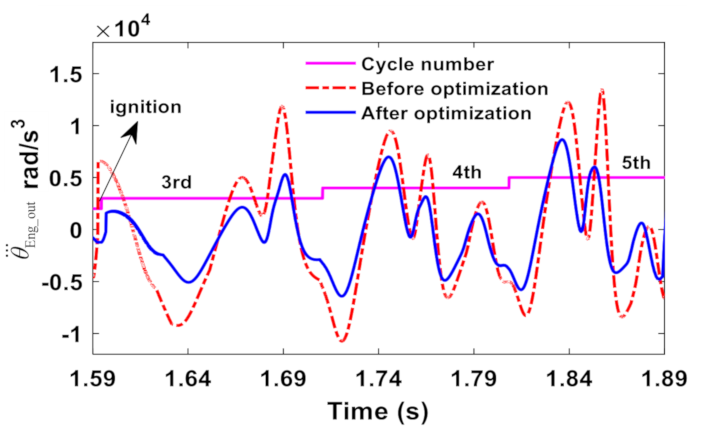
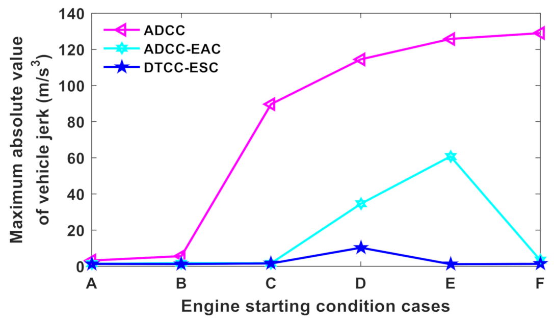
5.2.2. Jerk Analysis under Different Engine Starting Conditions

Since the vehicle jerk produced by the ADCC method was significantly less than 10 m/s3, which can be accepted by drivers (as shown in Figure 23) under cases A and B, the demand-angular acceleration of the engine before ignition was optimized for the other four cases (C, D, E and F) as shown in Figure 22. It can be seen from Figure 22 that different engine demand-angular accelerations are presented under different engine-starting conditions. It is mainly the influence of the engine-starting conditions that prevents the motor output torque from being limited by battery power and gives as much maximum torque as possible.
Figure 23 shows Ja-max values produced by the three control methods under six engine starting conditions. The Ja-max values with the ADCC method in cases C, D, E and F are greater than 85 m/s3. It is difficult for drivers and passengers to accept such large vehicle jerks. Compared with the ADCC method, although the ADCC-EAC method can effectively reduce vehicle jerks in cases A, B, C and F, the ADCC-EAC method could not effectively reduce jerks under cases D and E. Moreover, the Ja-max value in the case E is 60.8m/s3, which is also difficult to accept. For the Ja-max values generated by the DTCC-ESC method, it could be seen that the proposed DTCC-ESC method can effectively controlled the Ja-max values within 10m/s3 in the six cases of engine starting. Compared with the ADCC-EAC method, the Ja-max value of DTCC-ESC method at engine starting point E improved by 97.1%.
Therefore, the DTCC-ESC method proposed in this paper can effectively reduce jerks and improve driving comfort under different engine-starting conditions.

6. Conclusions

A compound power-split power transmission system model was first established and verified by bench experiments. The engine starting process was analyzed based on an equivalent lever method. Then, the problem of system jerks and vibrations caused by insufficient motor torque compensation under some engine starting conditions was analyzed. To solve this problem, this paper proposed a dynamic torque coordinated control for engine starting conditions (DTCC-ESC). Finally, three control methods (ADCC, ADCC-EAC, and DTCC-ESC) were selected for simulation and comparative analysis on the established hybrid electric vehicle model. The results showed that the proposed DTCC-ESC strategy can reduce system shocks under different engine start-up conditions during the mode switching process that includes engine start-up. Compared with the other two methods, the DTCC-ESC method had a better control effect.
In future research, the controller signal network delay can be considered to optimize the dynamic coordination control method to further reduce the system shock and vibration.

Author Contributions

Conceptualization, Y.S. and M.H.; methodology, Y.S.; software, C.F.; validation, J.H., D.Q. and Y.S.; formal analysis, D.Q.; investigation, C.F.; resources, M.H.; data curation, Y.Z.; writing—original draft preparation, Y.S.; writing—review and editing, J.H.; visualization, Y.S.; supervision, M.H.; project administration, J.H.; funding acquisition, M.H. All authors have read and agreed to the published version of the manuscript.

Funding

This research was funded in part by the NSFC Program (No. 61872217, No. U1701262, No. U1801263, No. 51675062), the research is also sponsored in part by the Guangdong Provincial Key Laboratory of Cyber-Physical Systems, as well as be sponsored in part by the Industrial Internet innovation and development project of ministry of industry and information technology.

Institutional Review Board Statement

Not applicable.

Informed Consent Statement

Not applicable.

Data Availability Statement

Not applicable.

Conflicts of Interest

The authors declare no conflict of interest.

Abbreviations

ADCCActive damping compensation control
ADCC-EACActive damping compensation control with engine active control
ADFC-SRActive damping feedback compensation control considering the system resonance
APPAcceleration pedal position
DTCC-ESCDynamic torque coordinated control considering engine starting conditions
ECVTElectric continuous variable transmission
ERTEngine ripple torque
EVElectric vehicle
ICAInitial crankshaft angle
IVCTIntake valve close timing
MG1Small motor 1
MG2Big motor 2
MTMode transition
PHEVPlug-in hybrid electric vehicle
PIDProportion integration differentiation
PSPPiston stop position
SOCState of charge
TDSTorsional damper spring
TIEquivalent elastic shaft of the tire and half shaft

References

  1. Ouyang, M.; Du, J.; Peng, H.; Wang, H.; Feng, X.; Song, Z. Progress review of US-China joint research on advanced technologies for plug-in electric vehicles. Sci. China Technol. Sci. 2018, 61, 1431–1445. [Google Scholar] [CrossRef]
  2. Liu, T.; Hu, X.; Hu, W.; Zou, Y. A heuristic planning reinforcement learning-based energy management for power-split plug-in hybrid electric vehicles. IEEE Trans. Ind. Inform. 2019, 15, 6436–6445. [Google Scholar] [CrossRef]
  3. Jinquan, G.; Hongwen, H.; Jiankun, P.; Nana, Z. A novel MPC-based adaptive energy management strategy in plug-in hybrid electric vehicles. Energy 2019, 175, 378–392. [Google Scholar] [CrossRef]
  4. Kuang, M.L. An investigation of engine start-stop NVH in a power split powertrain hybrid electric vehicle. SAE Tech. Pap. 2006. [Google Scholar] [CrossRef]
  5. Hwang, H.Y. Minimizing seat track vibration that is caused by the automatic start/stop of an engine in a power-split hybrid electric vehicle. J. Vib. Acoust. 2013, 135, 061007. [Google Scholar] [CrossRef]
  6. Chen, J.S.; Hwang, H.Y. Engine automatic start–stop dynamic analysis and vibration reduction for a two-mode hybrid vehicle. Proc. Inst. Mech. Eng. Part D J. Automob. Eng. 2013, 227, 1303–1312. [Google Scholar] [CrossRef]
  7. Huang, K.; Xiang, C.; Ma, Y.; Wang, W.; Langari, R. Mode shift control for a hybrid heavy-duty vehicle with power-split transmission. Energies 2017, 10, 177. [Google Scholar] [CrossRef]
  8. Hong, S.; Choi, W.; Ahn, S.; Kim, Y.; Kim, H. Mode shift control for a dual-mode power-split-type hybrid electric vehicle. Proc. Inst. Mech. Eng. Part D J. Automob. Eng. 2014, 228, 1217–1231. [Google Scholar] [CrossRef]
  9. Zuo, Y.H.; Xiang, C.L.; Yan, Q.D.; Wang, Y.Z. Engine start control strategy research for parallel-series hybrid electrical vehicles. In Proceedings of the 8th World Congress on Intelligent Control and Automation, Jinan, China, 7–9 July 2010; pp. 2097–2102. [Google Scholar]
  10. Gao, A.Y.; Fu, Z.M.; Tao, F.Z. Dynamic coordinated control based on sliding mode controller during mode switching with ICE starting for an HEV. IEEE Access 2020, 8, 60428–60443. [Google Scholar] [CrossRef]
  11. Liu, D.; Zhang, J.; Zhang, D.; Liu, G.; Yu, H. Experimental and numerical analysis of the seat track vibrations caused by engine starts in a power-split hybrid electric vehicle. Proc. Inst. Mech. Eng. Part D J. Automob. Eng. 2017, 231, 395–404. [Google Scholar] [CrossRef]
  12. Liu, D.; Yu, H.; Zhang, J. Multibody dynamics analysis for the coupled vibrations of a power split hybrid electric vehicle during the engine start transition. Proc. Inst. Mech. Eng. Part K J. Multi-Body Dyn. 2016, 230, 527–540. [Google Scholar] [CrossRef]
  13. Canova, M.; Guezennec, Y.; Yurkovich, S. On the control of engine start/stop dynamics in a hybrid electric vehicle. J. Dyn. Syst. Meas. Control 2009, 131, 061005. [Google Scholar] [CrossRef]
  14. Davis, R.I.; Lorenz, R.D. Engine torque ripple cancellation with an integrated starter alternator in a hybrid electric vehicle: Implementation and control. IEEE Trans. Ind. Appl. 2003, 39, 1765–1774. [Google Scholar] [CrossRef]
  15. Zhao, Z.; Dai, X.; Wang, C.; Zhang, T.; Yuan, X. Coordinated control of driving mode switching of compound power-split hybrid electric car. Automot. Eng. 2015, 37, 260–265. [Google Scholar]
  16. Shen, D.; Gühmann, C.; Zhang, T.; Dong, X. Coordinated control strategy in engine starting process for a novel compound power-split hybrid electric vehicle. In Proceedings of the ASME Internal Combustion Engine Fall Technical Conference, San Diego, CA, USA, 4–7 November 2018. [Google Scholar]
  17. Lin, Y.; Qin, D.; Hu, M.; Jiang, G. Torque coordination control strategy in engine starting process for a single motor hybrid electric vehicle. Int. J. Electr. Hybrid Veh. 2018, 10, 177–196. [Google Scholar] [CrossRef]
  18. Tomura, S.; Ito, Y.; Kamichi, K.; Yamanaka, A. Development of vibration reduction motor control for series-parallel hybrid system. SAE Tech. Pap. 2006. [Google Scholar] [CrossRef]
  19. Wang, C.; Zhao, Z.; Zhang, T.; Li, M. Mode transition coordinated control for a compound power-split hybrid car. Mech. Syst. Signal Process. 2017, 87, 192–205. [Google Scholar] [CrossRef]
  20. Su, Y.; Hu, M.; Su, L.; Qin, D.; Zhang, T.; Fu, C. Dynamic coordinated control during mode transition process for a compound power-split hybrid electric vehicle. Mech. Syst. Signal Process. 2018, 107, 221–240. [Google Scholar] [CrossRef]
  21. Li, M.; Zhao, Z.; Jiang, L.; Tang, X. Subsection coordinated control during mode transition for a compound power-split system. SAE Tech. Pap. 2019. [Google Scholar] [CrossRef]
  22. Zhuang, W.; Kum, D.; Peng, H.; Wang, L.; Li, D. Optimal engine starts of an input-split hybrid electric vehicle. SAE Int. J. Altern. Powertrains 2015, 4, 343–351. [Google Scholar] [CrossRef]
  23. Zhao, Z.; Jiang, L.; Wang, C.; Li, M. Engine start-up optimal control for a compound power-split hybrid powertrain. Mech. Syst. Signal Process. 2019, 120, 365–377. [Google Scholar] [CrossRef]
  24. Zhu, Y.; Wu, Z.; Lu, K. Transition rules among different vehicle driving modes for power-split powertrain hybrid electric vehicle. J. TongJi Univ. (Nat. Sci.) 2009, 37, 948–954. [Google Scholar]
  25. Zeng, X.; Yang, N.; Wang, J.; Song, D.; Zhang, N.; Shang, M.; Liu, J. Predictive-model-based dynamic coordination control strategy for power-split hybrid electric bus. Mech. Syst. Signal Process. 2015, 60, 785–798. [Google Scholar] [CrossRef]
  26. Su, Y.; Hu, M.; Su, L.; Qin, D.; Zhang, Y. Dynamic coordinated control during mode transition process for a plug-in hybrid electric vehicle. IEEE Access 2019, 7, 53891–53908. [Google Scholar] [CrossRef]
  27. Zeng, X.; Wang, Y.; Song, D.; Zhu, L.; Tian, G.; Li, Z. Coordinated control algorithm of a dual motor for an electric variable transmission hybrid system. IEEE Access 2018, 6, 53669–53682. [Google Scholar] [CrossRef]
  28. Syed, F.U.; Kuang, M.L.; Ying, H. Active damping wheel-torque control system to reduce driveline oscillations in a power-split hybrid electric vehicle. IEEE Trans. Veh. Technol. 2009, 58, 4769–4785. [Google Scholar] [CrossRef]
  29. Tang, X.; Zhang, D.; Liu, T.; Khajepour, A.; Yu, H.; Wang, H. Research on the energy control of a dual-motor hybrid vehicle during engine start-stop process. Energy 2019, 166, 1181–1193. [Google Scholar] [CrossRef]
  30. Zhu, F.; Chen, L.; Yin, C.; Shu, J. Dynamic modelling and systematic control during the mode transition for a multi-mode hybrid electric vehicle. Proc. Inst. Mech. Eng. Part D J. Automob. Eng. 2013, 227, 1007–1023. [Google Scholar] [CrossRef]
  31. Zhou, L. Study the Internal Combustion Engine; Machinery Industry Press: China, 2011. [Google Scholar]
  32. Guzela, L.; Wendell, C.H. Introduction to Modeling and Control of Internal Combustion Engine; Springer: Berlin, Germany, 2016. [Google Scholar]
  33. Yuan, D.; Xu, Y.; Li, X. Variable Frequency System of Permanent Magnet Synchronous Motor and Control; Mechanical Industry Press: China, 2015. [Google Scholar]
  34. Su, Y.; Hu, M.; Su, L.; Qin, D.; Liu, Y. Study on dynamic characteristics of electromechanical coupling in mode switching process of multi-power transmission system considering internal and external excitation. In Proceedings of the JSME International Conference on Motion and Power Transmissions, Kyoto, Japan, 1–3 March 2017; pp. 545–550. [Google Scholar]
  35. Benford, H.L.; Leising, M.B. The lever analogy: A new tool in transmission analysis. In SAE International Congress and Exposition; SAE Technical Paper 810102; SAE International: Detroit, MI, USA, 1981. [Google Scholar]
  36. Yu, H.S.; Zhang, J.W.; Zhang, T. Control strategy design and experimental research on a four-shaft electronic continuously variable transmission hybrid electric vehicle. Proc. Inst. Mech. Eng. Part D J. Automob. Eng. 2012, 226, 1594–1612. [Google Scholar] [CrossRef]
  37. Zhang, Y.; Mi, C. Automotive Power Transmission Systems; John Wiley & Sons: Hoboken, NJ, USA, 2018; pp. 431–436. [Google Scholar] [CrossRef]
  38. Wei, X.; Pisu, P.; Rizzoni, G.; Yurkovich, S. Dynamic modeling of a hybrid electric drivetrain for fuel economy, performance and driveability evaluations. In Proceedings of the ASME 2003 International Mechanical Engineering Congress and Exposition, Washington, DC, USA, 15–21 November 2003; pp. 443–450. [Google Scholar]
  39. Robinette, D.; Orlando, J. Control strategy and energy recovery potential for P2 parallel hybrid step gear automatic transmissions. SAE Tech. Pap 2019. [Google Scholar] [CrossRef]
  40. Mirjalili, S. Genetic algorithm. In Evolutionary Algorithms and Neural Networks; Springer: Cham, Switzerland, 2019; pp. 43–55. [Google Scholar]
  41. Yu, S.; Zhang, Y.; Dong, G.; Li, L. Fuel injection optimization during engine quick start by means of cycle-by-cycle control strategy for HEV application. SAE Tech. Pap. 2009. [Google Scholar] [CrossRef]
  42. Su, Y.; Su, L.; Hu, M.; Qin, D.; Fu, C.; Yu, H. Modeling and dynamic response analysis of a compound power-split hybrid electric vehicle during the engine starting process. IEEE Access 2020, 8, 186585–186598. [Google Scholar] [CrossRef]
Figure 1. Structure diagram of the compound PS-PHEV.
Applsci 11 02085 g001
Figure 2. Schematic diagram of a single cylinder engine.
Applsci 11 02085 g002
Figure 3. Torsional stiffness characteristic curve.
Applsci 11 02085 g003
Figure 4. Test bench for a PS-PHEV.
Applsci 11 02085 g004
Figure 5. Model validation of the powertrain system: (a) engine output torque; (b) drive shaft speed; (c) drive shaft speed error.
Applsci 11 02085 g005
Figure 6. Lever chart during engine starting process.
Applsci 11 02085 g006
Figure 7. Problem description during engine starting process.
Applsci 11 02085 g007
Figure 8. Block diagram of the dynamic torque coordinated control strategy.
Applsci 11 02085 g008
Figure 9. Intake valve close timing optimization before engine ignition.
Applsci 11 02085 g009
Figure 10. Effect of IVCT on engine output torque with θ i c a = 85 deg.
Applsci 11 02085 g010
Figure 11. Effect of ICA on engine output torque with θ i v c t = 150 deg.
Applsci 11 02085 g011
Figure 12. Jerk analysis based on engine working cycle number.
Applsci 11 02085 g012
Figure 13. Flow diagram of the fuel injection and ignition timing optimization.
Applsci 11 02085 g013
Figure 14. Optimization results of injection volume and ignition timing: (a) injection volume; (b) ignition timing.
Applsci 11 02085 g014
Figure 15. Optimization results of the first three working cycles after ignition.
Applsci 11 02085 g015
Figure 16. Bode diagram of system before and after damping feedback control.
Applsci 11 02085 g016
Figure 17. Zero-pole distribution diagram based on root locus.
Applsci 11 02085 g017
Figure 18. Engine starting condition points.
Applsci 11 02085 g018
Figure 19. Optimized engine demand-angular acceleration before ignition under case D.
Applsci 11 02085 g019
Figure 20. Comparison results of three control methods under case D: (a) output torque of power source; (b) output torque of power source; (c) output torque of power source.
Applsci 11 02085 g020
Figure 21. Jerk results of three control methods under case D.
Applsci 11 02085 g021
Figure 22. Optimized engine demand-angular acceleration before ignition.
Applsci 11 02085 g022
Figure 23. Jerk analysis under six engine starting conditions.
Applsci 11 02085 g023
Table 1. Main PS-PHEV Parameters.
ParametersValues
Engine maximum torque/speed (Nm/rpm)145/3600
MG1/MG2 maximum torque (Nm)96/246
Planetary parameter of front row i 1 −3.179
Planetary parameter of rear row i 2 2.342
Final drive ratio i 0 4.044
Carrier inertia I C (kg⋅m2)0.0039
Ring inertia I R (kg⋅m2)0.0017
Inertia ( I M G 1 + I S 1 ) of MG1 and S 1 (kg⋅m2)0.041
Inertia ( I M G 2 + I S 2 ) of MG2 and S 2 (kg⋅m2)0.0723
Engine inertia I E n g (kg⋅m2)0.18
Vehicle equivalent mass m v (kg)1538
Wheel radius r v (m)0.31
Vehicle frontal area A (m2)2.19
Air resistance coefficient C d 0.307
Tire rolling resistance coefficient0.0137
Rated capacity of battery (Ah)37
Rated voltage of battery (V)308
Equivalent TI torsional stiffness k T I (Nm⋅rad−1)2864
Equivalent TI torsional damping c T I (Nm⋅s⋅rad−1)15
Table 2. Engine Starting Other Conditions.
Engine Starting Other ConditionsEngine Coolant Temperature (°C)Battery Temperature (°C)SOC
Case A25400.2
Case B25400.15
Case C25400.2
Case D25400.8
Case E25400.8
Case F25400.8
Table 3. Three Control Method Description.
Control MethodsMethod Description
ADCCOnly feedback damping torque in Equation (22) obtained by a PID controller
ADCC-EACEngine active control + feedback damping torque in Equation (22) obtained by a PID controller
DTCC-ESCEngine segment active control + feedforward control considering engine starting conditions and feedback control considering engine optimal target speed + ADFC-SR
Table 4. Comparison Results of Jerks under Case D.
Control MethodsJa-max (m/s3)Improvement of Ja-max (%)
ADCC114.5
ADCC-EAC34.5869.8
DTCC-ESC9.9491.32
Publisher’s Note: MDPI stays neutral with regard to jurisdictional claims in published maps and institutional affiliations.

