
Flexural Strength of Composite Deck Slab with Macro Synthetic Fiber Reinforced Concrete


Abstract
1. Introduction
2. Mechanical Properties of MFRC
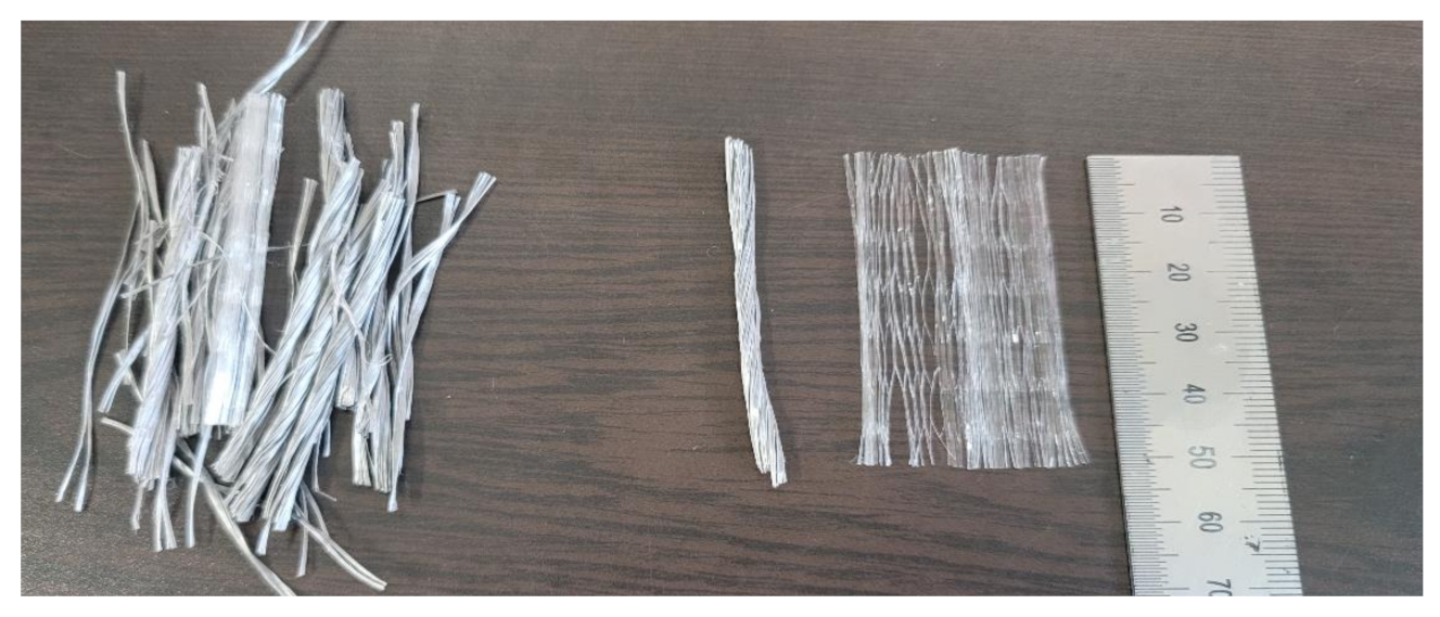
2.1. Characteristics of MFRC
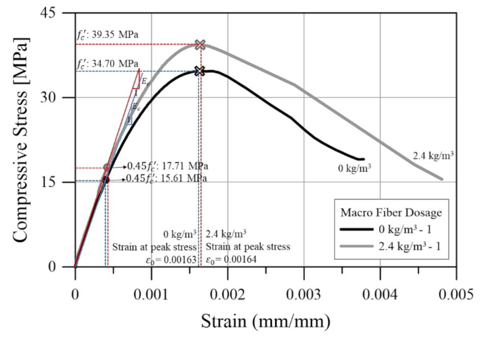
2.2. Compressive Behavior
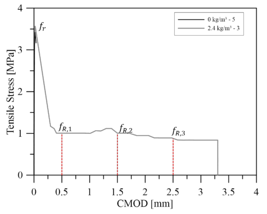
2.3. Tensile Behavior
3. Experimental Program
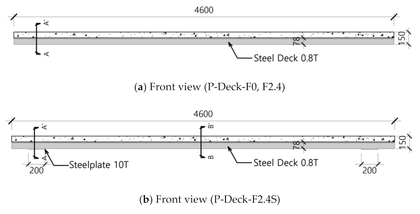
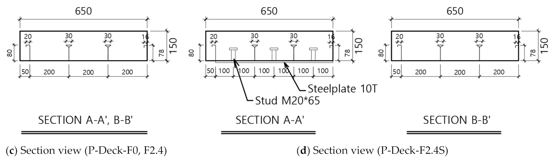
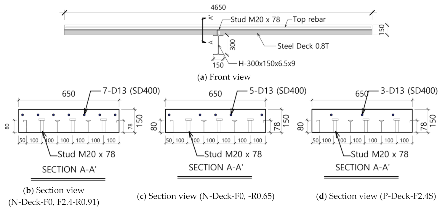
3.1. Test Plan and Specimen Design
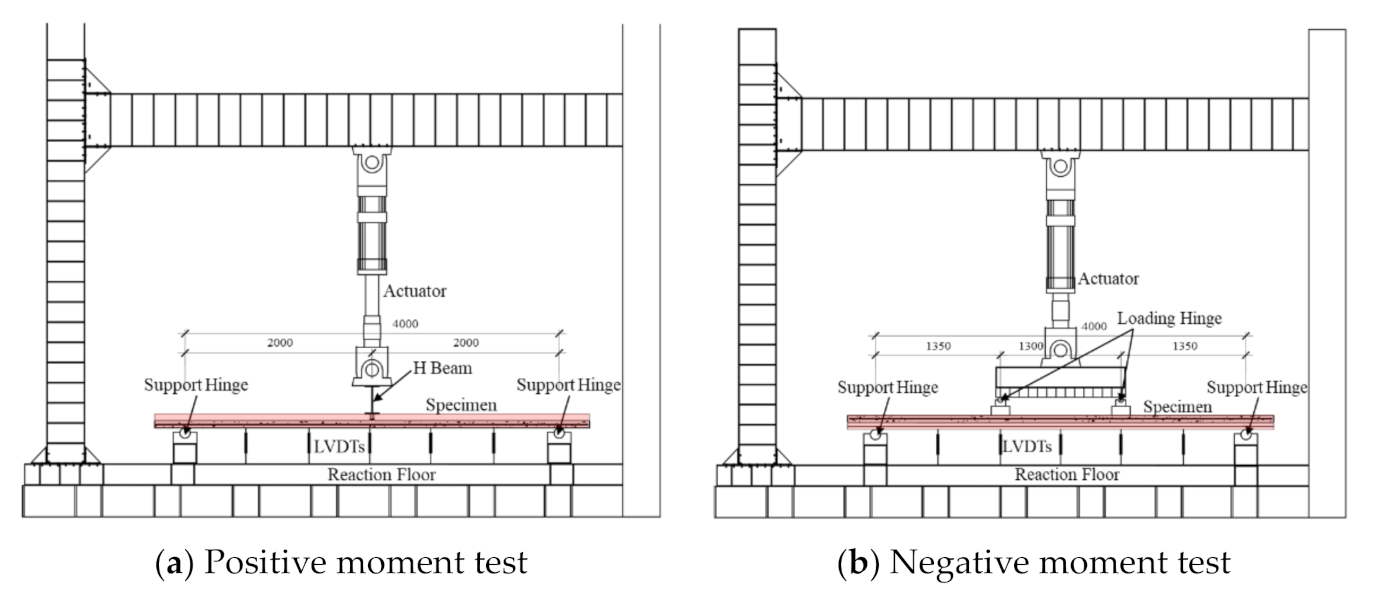
3.2. Test Setup
4. Test Results
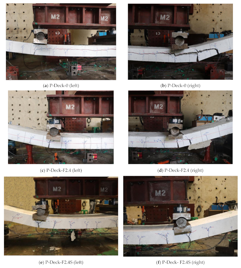
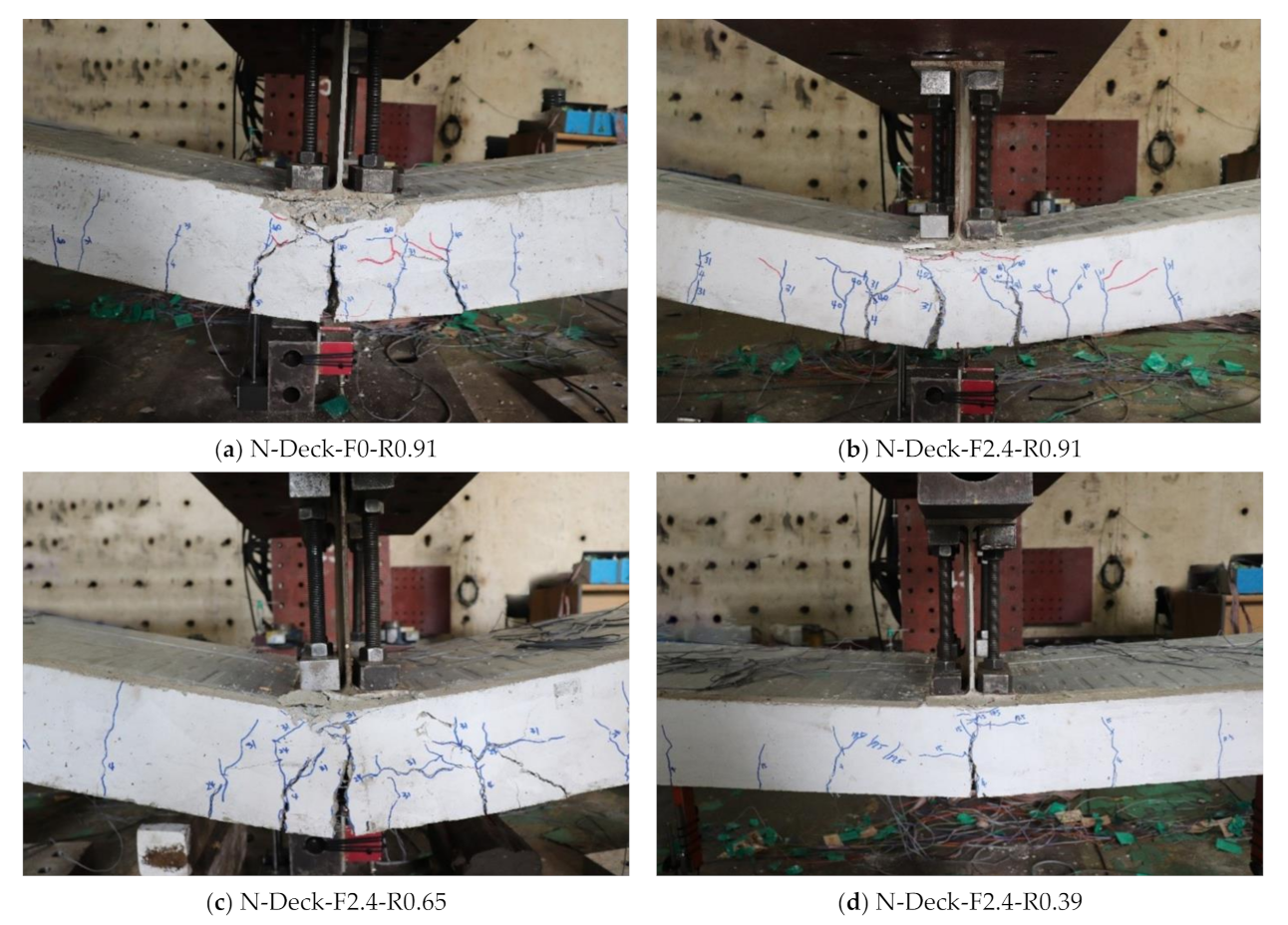
4.1. Crack Propagation and Failure Modes
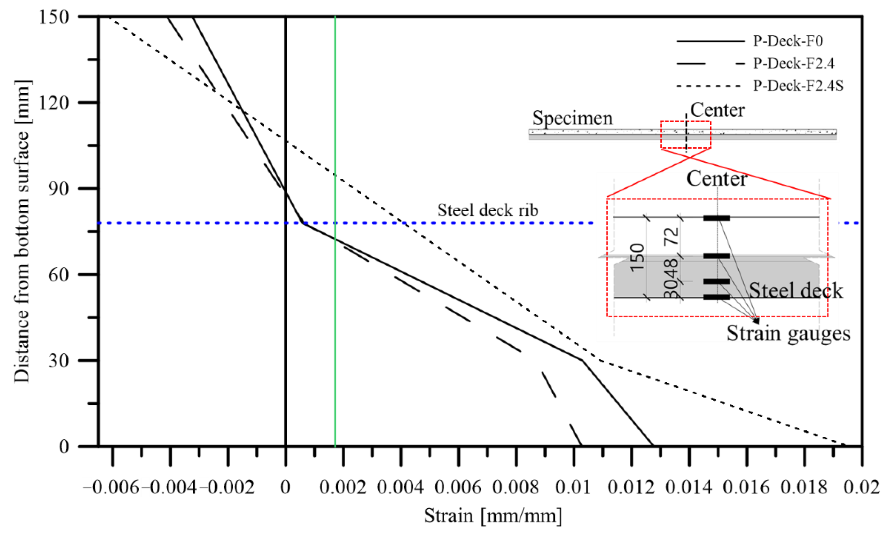
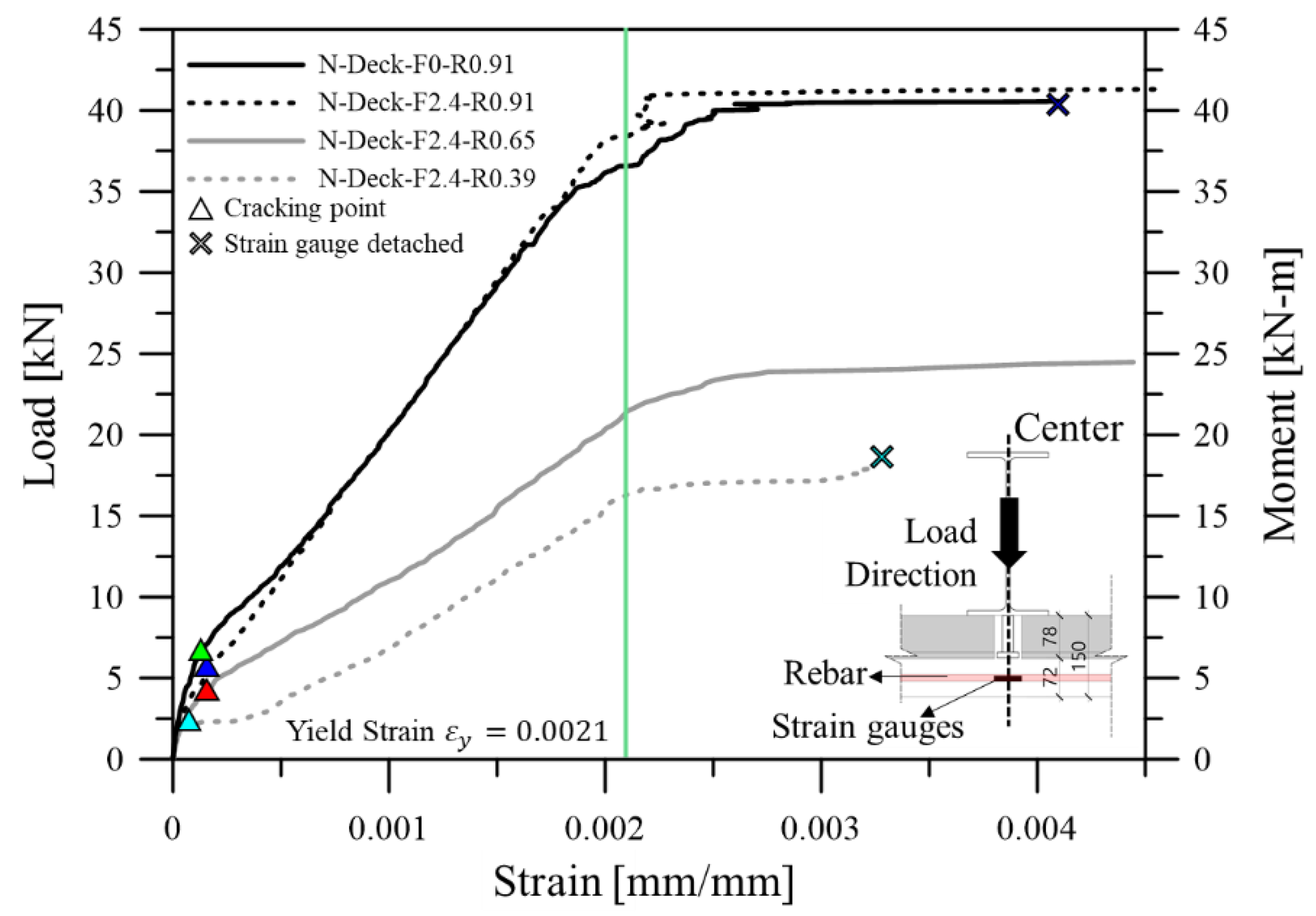
4.2. Strain Distribution of a Section
5. Ultimate Flexural Strength of the MFRC Steel Deck
6. Conclusions
- (1)
- In the uniaxial compressive strength test of concrete reinforced with macro-synthetic fiber, compressive strength and modulus of elasticity increased. Furthermore, the strength decreased more gradually after achieving the maximum compressive strength of the MFRC. In the flexural and splitting tensile strength tests, unlike other research results [6,7] in which the tensile strength increased, there was little change in both parameters. It is judged that when the macro-synthetic fiber dosage is 2.4 kg/m3, the fiber dosage is small; thus, the maximum tensile strength cannot be increased. However, after achieving the maximum strength, the specimens had sufficient residual strength until fracture.
- (2)
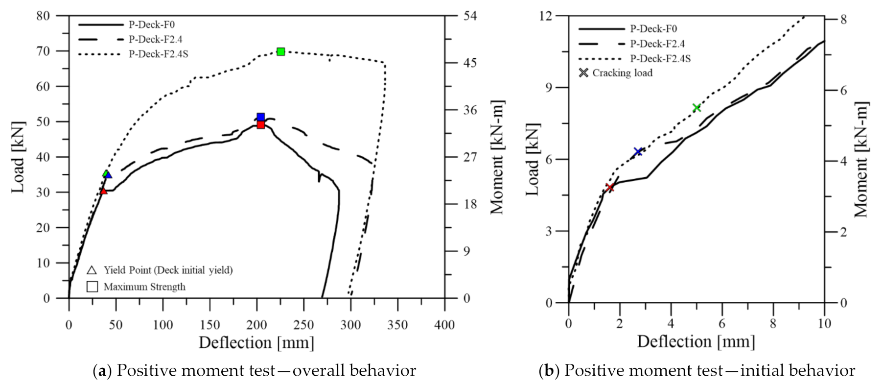
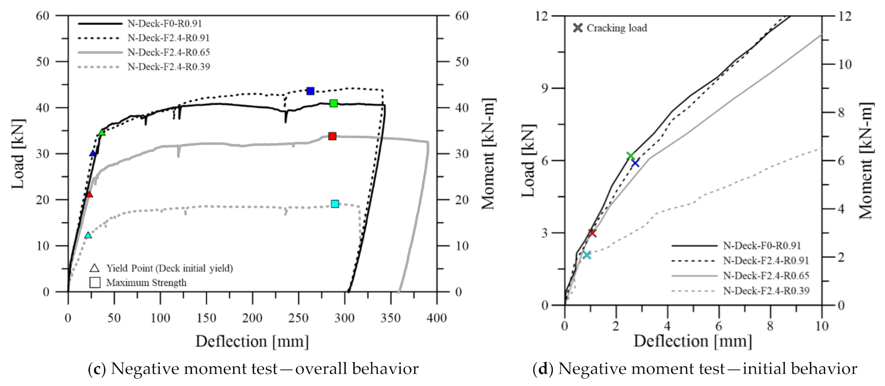
- The flexural strength and cracking load of all specimens increased according to macro synthetic fiber dosage. The increase in flexural strength was more pronounced in the negative moment region than in the positive moment region. In addition, since it was confirmed that the MFRC steel deck had greater flexural stiffness until yielding, it will be necessary to quantitatively evaluate the effect of MFRC on the effective flexural stiffness of steel decking in future studies.
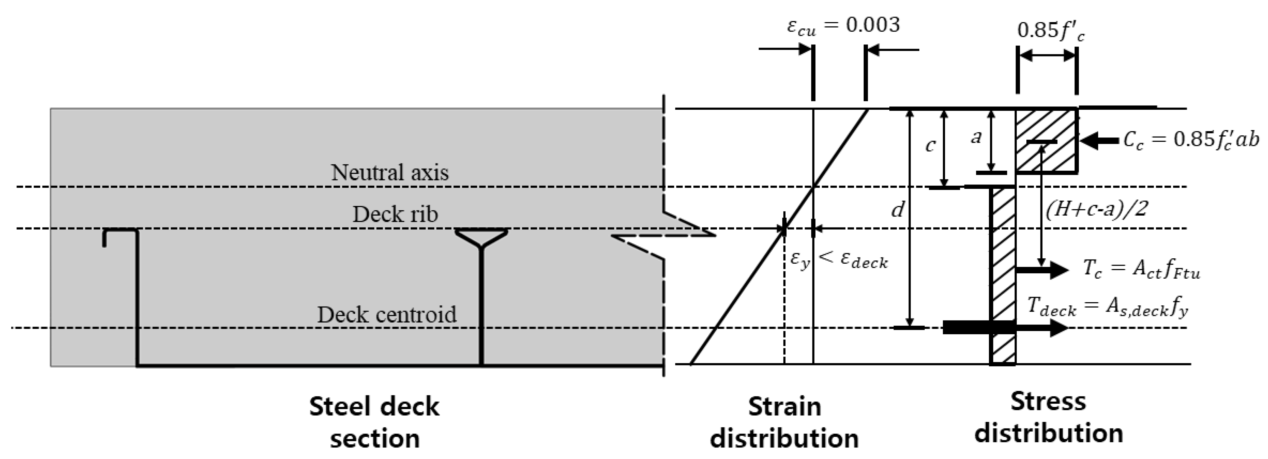
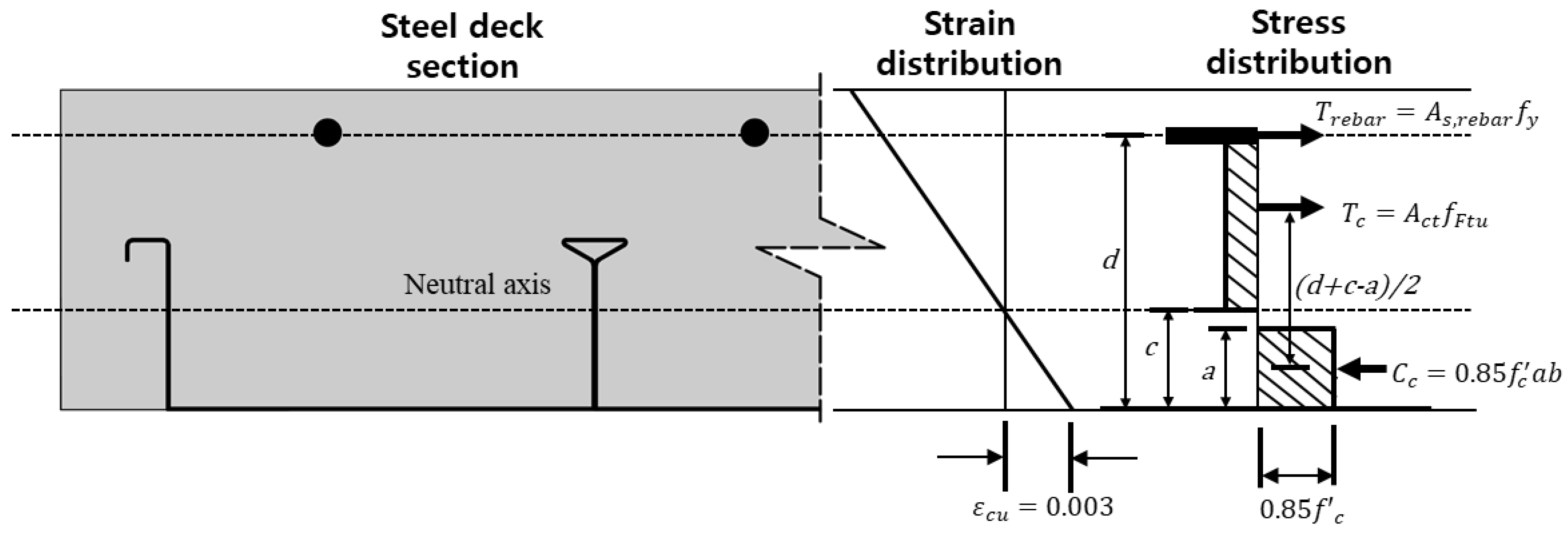
- (3)
- According to the experimental results, we proposed a flexural strength model of a steel deck plate containing macro synthetic fiber. This model showed greater accuracy than the current standard when comparing the experimental results. However, due to the simple design process described here, the equation proposed does not consider the compressive force contributed by the steel deck. If the compressive force of the steel deck was considered in the precise analysis, it would be possible to predict flexural strength more accurately.
- (4)
- In future studies, the effect of macro-synthetic fiber on flexural strength could be predicted more accurately by performing flexural strength evaluation using various macro-synthetic fibers. Furthermore, when fiber-reinforced concrete is applied to a new slab system, the contribution of the fiber to the flexural strength could be examined.
Author Contributions
Funding
Institutional Review Board Statement
Informed Consent Statement
Data Availability Statement
Conflicts of Interest
References
- Kim, M.-H.; Kim, J.-H.; Kim, Y.-R.; Kim, Y.-D. An Experimental Study on the Mechanical Properties of HPFRCCS Reinforced with the Micro and Macro Fibers. J. Korea Concr. Inst. 2005, 17, 263–271. [Google Scholar] [CrossRef]
- Chun, B.; Yoo, D.Y. Hybrid Effect of Macro and Micro Steel Fibers on the Pullout and Tensile Behaviors of Ultra-High-Performance Concrete. Compos. Part B Eng. 2019, 162, 344–360. [Google Scholar] [CrossRef]
- Şahin, Y.; Köksal, F. The influences of matrix and steel fibre tensile strengths on the fracture energy of high-strength concrete. Constr. Build. Mater. 2011, 25, 1801–1806. [Google Scholar] [CrossRef]
- Lawler, J.S.; Zampini, D.; Shah, S.P. Microfiber and Macrofiber Hybrid Fiber-Reinforced Concrete. J. Mater. Civ. Eng. 2005, 17, 595–604. [Google Scholar] [CrossRef]
- Ryu, H.-S.; Kim, D.-M.; Shin, S.-H.; Ryu, I.-H.; Joe, J.-M. Evaluation on Mechanical Properties of Organic of Fiber Reinforced Concrete Using Macro Forta Fiber. J. Korea Inst. Build. Constr. 2017, 17, 321–329. [Google Scholar] [CrossRef]
- Oliari, G.; Estela, M.I.K.; Alastair, M.; Mahbube, S.; Kazem, G. Self-Compacting Concrete Reinforced with Twisted-Bundle Macro-Synthetic Fiber. Appl. Sci. 2019, 9, 2543. [Google Scholar] [CrossRef]
- Nematzadeh, M.; Hasan-Nattaj, F. Compressive Stress-Strain Model for High-Strength Concrete Reinforced with Forta-Ferro and Steel Fibers. J. Mater. Civ. Eng. 2017, 29, 04017152. [Google Scholar] [CrossRef]
- Lee, M.S.; Chung, J.H.; Son, D.H.; Choi, C.S. Flexural Strength Evaluation of Reinforced Concrete Slabs with Macro Synthetic Fibers. J. Archit. Inst. Korea 2020, 36, 241–248. (In Korean) [Google Scholar]
- Hong, G.H. Structural Performance of Steel Fiber Reinforced Concrete Continuous Slab without Reinforcement. J. Archit. Inst. Korea Struct. Constr. 2015, 31, 11–18. [Google Scholar] [CrossRef]
- ACI Committee. ACI 544.4R-88, Guide to Design with Fiber-Reinforced Concrete; ACI Committee: Farmington Hill, MI, USA, 1988. [Google Scholar]
- Taerwe, L.; Matthys, S. Fib Model Code for Concrete Structures 2010; Ernst & Sohn, Wiley: Berlin, Germany, 2013. [Google Scholar]
- FORTA-FERRO Company. Macro Synthetic Fiber Technical Report; FORTA Concrete Fiber Company: Grove City, PA, USA, 2018. [Google Scholar]
- Smirnova, O.; Kharitonov, A.; Belentsov, Y. Influence of polyolefin fibers on the strength and deformability properties of road pavement concrete. J. Traffic Transp. Eng. 2019, 6, 407–417. [Google Scholar] [CrossRef]
- Daneshfar, M.; Hassani, A.; Aliha, M.R.M.; Berto, F. Evaluating Mechanical Properties of Macro-Synthetic Fiber-Reinforced Concrete with Various Types and Contents. Strength Mater. 2017, 49, 618–626. [Google Scholar] [CrossRef]
- Nematzadeh, M.; Fallah-Valukolaee, S. Erosion resistance of high-strength concrete containing forta-ferro fibers against sulfuric acid attack with an optimum design. Constr. Build. Mater. 2017, 154, 675–686. [Google Scholar] [CrossRef]
- Hasan-Nattaj, F.; Nematzadeh, M. The effect of forta-ferro and steel fibers on mechanical properties of high-strength concrete with and without silica fume and nano-silica. Constr. Build. Mater. 2017, 137, 557–572. [Google Scholar] [CrossRef]
- Korean Agency for Technology and Standards. KS B 2402. Standard Test Method for Concrete Slump; Korean Agency for Technology and Standards: Seoul, Korea, 2017; pp. 1–14.
- Korean Agency for Technology and Standards. KS F 2403. Standard Test Method for Making and Curing Concrete Specimens; Korean Agency for Technology and Standards: Seoul, Korea, 2014; pp. 1–14.
- Korean Agency for Technology and Standards. KS F 2405. Standard Test Method for Compressive Strength of Concrete; Korean Agency for Technology and Standards: Seoul, Korea, 2014; pp. 1–16.
- ACI Committee. ACI 318-19. Building Code Requirement for Structural Concrete and Commentary; ACI Committee: Farmington Hill, MI, USA, 2019. [Google Scholar]
- Pauw, A. Static Modulus of Elasticity of Concrete as Affected by Density. ACI J. Proc. 2016, 57, 679–688. [Google Scholar] [CrossRef][Green Version]
- Korean Agency for Technology and Standards. KS F 2423. Method of Test for Splitting Tensile Strength of Concrete; Korean Agency for Technology and Standards: Seoul, Korea, 2016; pp. 1–12.
- Korean Agency for Technology and Standards. KS F 2408. Method of Test for Flexural Strength of Concrete; Korean Agency for Technology and Standards: Seoul, Korea, 2016; pp. 1–16.
- BSI. EN, BS. 14651. Test Method for Metallic Fibre Concrete-Measuring the Flexural Tensile Strength (Limit of Proportionally (LOP), Residual); BSI: London, UK, 2007; pp. 1–20. [Google Scholar]
- Porter, M.L.; Ekberg, C.E. Design Recommendations for Steel Deck Floor Slabs. J. Struct. Div. ASCE 1976, 102, 2121–2136. [Google Scholar] [CrossRef]
- Korean Agency for Technology and Standards. KS D 3506. Hot-Dip Zinc-Coated Steel Sheets and Coil; Korean Agency for Technology and Standards: Seoul, Korea, 2018; pp. 1–60.
- Korean Agency for Technology and Standards. KS B 0802. Method of Tensile Test for Metallic Materials; Korean Agency for Technology and Standards: Seoul, Korea, 2013; pp. 1–7.
- Chung, J.H. Flexural and Shear Behavior of Donut Type Voided Slabs. Ph.D. Thesis, Hanyang University, Seoul, Korea, 2015. [Google Scholar]
- ASCE. Standard for the Structural Design of Composite Slabs and Standard Practice for Construction and Inspection of Composite Slabs; ANSI/ASCE 2-84; American Society of Civil Engineers: New York, NY, USA, 1994. [Google Scholar]
- Easterling, W.S.; Young, C.S. Strength of Composite Slabs. J. Struct. Eng. ASCE 1992, 118, 2370–2389. [Google Scholar] [CrossRef]
- Lamport, W.B.; Porter, M.L. Deflection Predictions for Concrete Slabs Reinforced with Steel Decking. ACI Struct. J. 1990, 87, 564–570. [Google Scholar]
- Kim, K.C.; Yang, I.H.; Joh, C.B. Material Properties and Structural Characteristics on Flexure of Steel Fiber-Reinforced Ultra-High-Performance Concrete. J. Korea Concr. Inst. 2016, 28, 177–185. [Google Scholar] [CrossRef]


| Tensile Strength (MPa) | Modulus of Elasticity (GPa) | Length (mm) | Diameter (mm) | Aspect Ratio |
|---|---|---|---|---|
| 54.9 | 4.7 | 54 | 0.34 | 159 |
| W/C (%) | S/a (%) | Unit Weight (kg/m3) | |||||
|---|---|---|---|---|---|---|---|
| C | W | S | G | AD | MF | ||
| 54.9 | 45.5 | 365 | 200.7 | 854 | 1022.7 | 3.29 | 0 |
| 2.4 | |||||||
| No. | (kg/m3) | (MPa) | (mm/mm) | (MPa) |
|---|---|---|---|---|
| 1 | 0 | 34.70 | 0.00163 | 38,912 |
| 2 | 34.98 | 0.00167 | 35,457 | |
| 3 | 35.74 | 0.00143 | 41,128 | |
| 1 | 2.4 | 39.35 | 0.00164 | 42,408 |
| 2 | 40.94 | 0.00140 | 46,054 | |
| 3 | 39.89 | 0.00194 | 32,934 |
(kg/m3) | No. | (MPa) | (MPa) | (MPa) | (MPa) | (MPa) | (MPa) |
|---|---|---|---|---|---|---|---|
| 0 | 1 | 3.07 | 3.62 | - | - | - | - |
| 2 | 2.78 | 3.50 | - | - | - | - | |
| 3 | 2.84 | 3.45 | - | - | - | - | |
| 4 | - | 4.22 | - | - | - | - | |
| 5 | - | 3.42 | - | - | - | - | |
| 2.4 | 1 | 3.09 | 3.28 | 1.44 | 1.39 | 1.06 | - |
| 2 | 2.55 | 3.44 | 1.45 | 1.45 | 1.11 | - | |
| 3 | 3.04 | 3.57 | 1.00 | 0.89 | 0.89 | ||
| 4 | - | 3.45 | - | - | - | - | |
| 5 | - | 3.11 | 1.28 | 1.22 | 1.11 | 0.95 |
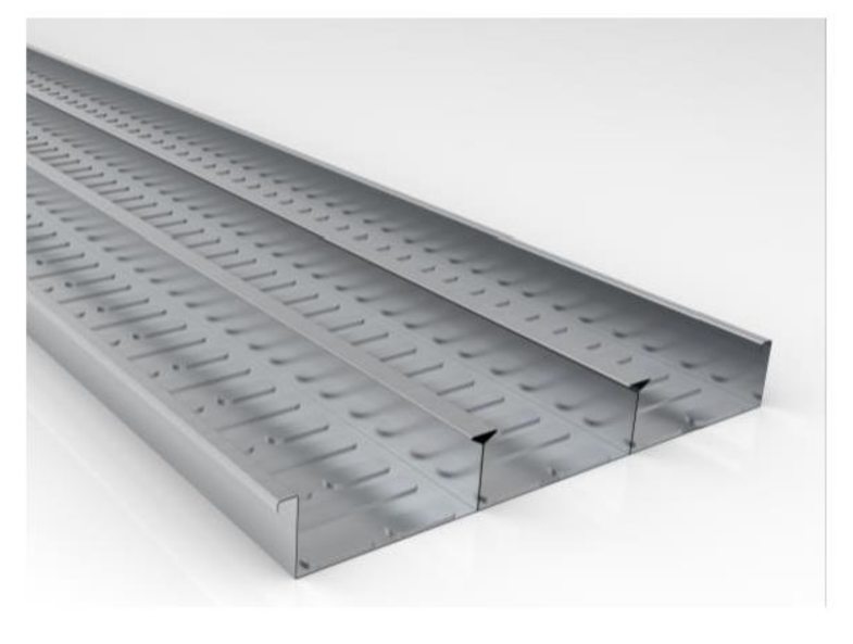
| Table 2 | Weight (kg/m2) | Section Area (mm2) | Centroid (mm) | Moment of Inertia (mm4) |
|---|---|---|---|---|
| 0.8 | 14.47 | 1075.2 | 25.29 | 915,107 |
| ID | Length | Width | Thickness | Shear Span Ratio | Macro Synthetic Fiber | Remarks | |||
|---|---|---|---|---|---|---|---|---|---|
| (mm) | (mm) | (mm) | (MPa) | (mm2) | (mm2) | (kg/m3) | |||
| P-Deck-0 | 4000 | 650 | 150 | 10.8 | 365 | 825.6 (Deck) | - | 0 | - |
| P-Deck-F2.4 | 2.4 | ||||||||
| P-Deck-F2.4S | Stud 3-M20 (Both ends) | ||||||||
| N-Deck-F0-R0.91 | 16 | 886.9 (7-D13) | 0 | - | |||||
| N-Deck-F2.4-R0.91 | 886.9 (7-D13) | 2.4 | |||||||
| N-Deck-F2.4-R0.65 | 633.5 (5-D13) | ||||||||
| N-Deck-F2.4-R0.39 | 380.1 (3-D13) |
| ID | Theoretical Value | Test Results | ||||||
|---|---|---|---|---|---|---|---|---|
(kN) | (mm) | (kN) | (kN) | (kN) | (mm) | (mm) | (mm) | |
| P-Deck-0 | 66.67 | 36.52 | 30.44 | 49.09 | 58.26 | 0.87 | 204.86 | 5.61 |
| P-Deck-F2.4 | 35.54 | 30.79 | 51.31 | 60.48 | 0.91 | 204.04 | 5.74 | |
| P-Deck-F2.4S | 26.80 | 26.78 | 69.82 | 78.99 | 1.18 | 225.16 | 8.40 | |
| N-Deck-F0-R0.91 | 39.02 | 32.04 | 30.39 | 40.95 | 50.12 | 1.28 | 288.97 | 9.02 |
| N-Deck-F2.4-R0.91 | 26.83 | 30.18 | 44.23 | 53.40 | 1.37 | 306.46 | 11.42 | |
| N-Deck-F2.4-R0.65 | 28.52 | 23.24 | 21.48 | 33.8 | 42.97 | 1.51 | 288.34 | 12.41 |
| N-Deck-F2.4-R0.39 | 17.50 | 21.65 | 12.39 | 19.09 | 28.26 | 1.62 | 291.35 | 13.46 |
| ID | Theoretical Value | Test Results | |||
|---|---|---|---|---|---|
(kN) | (kN) | (kN) | (mm) | ||
| P-Deck-0 | 12.17 | 4.85 | 14.02 | 1.85 | 1.15 |
| P-Deck-F2.4 | 6.26 | 15.43 | 2.37 | 1.27 | |
| P-Deck-F2.4S | 7.98 | 17.15 | 5.01 | 1.41 | |
| N-Deck-F0-R0.91 | 8.21 | 6.07 | 15.24 | 2.47 | 1.86 |
| N-Deck-F2.4-R0.91 | 5.85 | 15.02 | 2.71 | 1.83 | |
| N-Deck-F2.4-R0.65 | 3.47 | 12.64 | 1.37 | 1.54 | |
| N-Deck-F2.4-R0.39 | 2.26 | 11.43 | 1.03 | 1.39 | |
| (kN-m) | (kN) | (kN) | |||
|---|---|---|---|---|---|
| P-Deck-F2.4S | 47.43 | 70.26 | 78.99 | 1.18 | 1.12 |
| N-Deck-F2.4-R0.91 | 46.03 | 46.03 | 53.40 | 1.37 | 1.16 |
| N-Deck-F2.4-R0.65 | 34.04 | 34.04 | 42.97 | 1.51 | 1.26 |
| N-Deck-F2.4-R0.39 | 21.55 | 21.55 | 28.26 | 1.62 | 1.31 |
Publisher’s Note: MDPI stays neutral with regard to jurisdictional claims in published maps and institutional affiliations. |
© 2021 by the authors. Licensee MDPI, Basel, Switzerland. This article is an open access article distributed under the terms and conditions of the Creative Commons Attribution (CC BY) license (http://creativecommons.org/licenses/by/4.0/).
Share and Cite
Son, D.-H.; Bae, B.-I.; Lee, M.-S.; Lee, M.-S.; Choi, C.-S. Flexural Strength of Composite Deck Slab with Macro Synthetic Fiber Reinforced Concrete. Appl. Sci. 2021, 11, 1662. https://doi.org/10.3390/app11041662
Son D-H, Bae B-I, Lee M-S, Lee M-S, Choi C-S. Flexural Strength of Composite Deck Slab with Macro Synthetic Fiber Reinforced Concrete. Applied Sciences. 2021; 11(4):1662. https://doi.org/10.3390/app11041662
Chicago/Turabian StyleSon, Dong-Hee, Baek-Il Bae, Moon-Sung Lee, Moon-Seok Lee, and Chang-Sik Choi. 2021. "Flexural Strength of Composite Deck Slab with Macro Synthetic Fiber Reinforced Concrete" Applied Sciences 11, no. 4: 1662. https://doi.org/10.3390/app11041662
APA StyleSon, D.-H., Bae, B.-I., Lee, M.-S., Lee, M.-S., & Choi, C.-S. (2021). Flexural Strength of Composite Deck Slab with Macro Synthetic Fiber Reinforced Concrete. Applied Sciences, 11(4), 1662. https://doi.org/10.3390/app11041662