Article

Droop Method Development for Microgrids Control Considering Higher Order Sliding Mode Control Approach and Feeder Impedance Variation

1
Department of Electrical Engineering, Marvdasht Branch, Islamic Azad University, Marvdasht 73711, Iran
2
Department of Electrical Engineering and Automation, Aalto University, 02150 Espoo, Finland
*
Author to whom correspondence should be addressed.
Appl. Sci. 2021, 11(3), 967; https://doi.org/10.3390/app11030967
Submission received: 23 December 2020 / Revised: 11 January 2021 / Accepted: 18 January 2021 / Published: 21 January 2021
(This article belongs to the Special Issue Future Distribution Network Solutions)

Abstract

:
Due to the growing power demands in microgrids (MGs), the necessity for parallel production achieved from distributed generations (DGs) to supply the load required by customers has been increased. Since the DGs have to procure the demand in parallel mode, they are faced with several technical and economic challenges, such as preventing DGs overloading and not losing network stability considering feeder impedance variation. This paper presents a method that upgrades the droop controller based on sliding mode approach, so that DGs are able to prepare a suitable reactive power sharing without error even in more complex MGs. In the proposed strategy, the third-order sliding mode controller significantly reduces the V-Q error and increases the accuracy in adjusting the voltage at the DG output terminals. Various case studies conducted out in this paper validate the truthfulness of the proposed method, considering the stability analysis using Lyapunov function. Finally, by comparing the control parameters of the proposed technique with existing methods, the superiority, simplicity and effectiveness of the 3rd order sliding mode control (SMC) method are determined.

1. Introduction

The increasing use of distributed generation (DG) units in distribution networks has caused many concerns regarding the units implementation in microgrids (MGs). Among these matters, the reliability and quality of the power supply resources can be mentioned [1]. The operation of distributed generation units is possible in two ways, connected mode and islanding from the alternative current (AC) main network. According to the existing standards in the field of DG operation and control in MGs, if the main network is disconnected, the DG resources must be separated for less than 2 s [2]. The idea of using MG systems was introduced due to the ability of some DGs to operate in both grid connected and islanding modes; for example, if the MGs include several energy storage systems (ESSs), they can also perform in islanding mode. Since the DG control systems are designed to provide the ability to inject power in both grid connected and islanding modes, they usually are utilized to make the MG be smart, while the intelligent measurements are installed as shown in Figure 1 [3,4].
In the grid-connected mode, the conventional control methods like droop for inverters are based on the current control strategy in which the main grid imposes the frequency and voltage at the point of common coupling (PCC), while the inverters exchange the real and reactive power with the upstream network.
In the islanding mode, as there is no connection between the main network and the MG, the voltage and frequency is controlled by the DGs remained at it. Conversely, in the case of network connected mode, the network has no role in stabilizing the voltage and the frequency oscillations of the network. The autonomous islanded system must also control its voltage and frequency of the microgrid, because without controlling the voltage and frequency and due to the uncertainty in the load parameters and their changes, the voltage and frequency of the loads can deviate significantly from the nominal value, resulting in lose the proper function [5]. Moreover, in order to ensure that each of the distributed generation sources does not operate in conditions beyond its maximum power, the microgrid requires a precise power sharing strategy [6]. In an islanding MG, in order to prevent the overloading of any resource and the stable performance, DGs must be controlled in such a way as to provide all the required network load based on their nominal power. Proper management of active and reactive output power leads to an appropriate power sharing strategy, while no output voltages and frequency of DGs exceed the allowable range [7].
In decentralized power sharing techniques, the role of each DG unit is the same as the other ones and none of them has a more important role than the others. In decentralized MG control due to the lack of a central controller or telecommunications, more reliability is achieved. On the other hand, decentralized control provides the most independence in performance for each of the DG to maintain the system stability. In this way, each DG has its own local controller (LC) and as a result, there is no need for a telecommunications connection, a central controller, or a central storage. This means that the absence of any resources or components does not impede the operation of the MG. In this case, without the prerequisite to redesign the controller, a typical DM can be easily added or disconnected from the system [8,9]. Despite the fact that decentralized control seems to be flawless at first glance, recent studies indicate that there are some fundamental problems in using the conventional drop control method. This control method is mainly for the resources connected to the transmission lines with inductive properties. If is designed in low voltage networks that have resistive properties, it does not succeed in properly power sharing (especially reactive power) with appropriate accuracy. The reason for this, is the coupling between active and reactive output power of DGs in these conditions. In addition, inequality and asymmetry in feeder or cable impedance, which is a common problem in distribution networks, as well as the output impedance of DGs, make it challenging to precisely control the reactive power in an islanding mode. Another major problem of conventional droop control is its inability to distribute nonlinear loads and unbalanced loads considering multiple DGs [10,11,12,13].
To overcome the abovementioned problems, different improved droop control methods have been proposed [14]. In order to solve the problem of resistive networks, the reverse droop control method using the P-V and Q-f droop characteristics is proposed. The control approach proposed in [10] provide a reverse control method that allows multiple voltage source converters to operate in parallel in a MG. The proposed algorithm works well in both grid connected and islanding modes. In order to prevent the coupling of real and reactive power in low voltage networks, more strategies have been proposed [15]. This method, despite the proper operation in grid connected mode, but is not able to directly shares the active and reactive power in islanding status.
The conventional droop control method is determined due to the dependence of system dynamics on droop coefficients, source output impedance, line frequency and the maximum allowable value of frequency and voltage deviation, as well as the rated output power. Accordingly, it is not possible to have much control over the dynamics of the inverters independently. A complete small signal model of an islanding MG is presented, in which the dynamic analysis represents that by changing the power demand by the consumers, the low frequency modes of the power distribution system are displaced and can lead to instability [16]. To solve this problem, a simplified linear model of the system and based on it, a modified droop control strategy has been proposed to optimally achieve the power sharing while maintaining the stability [17]. Similarly, the use of inductive and virtual impedance loops is presented to improve the performance of the power sharing accuracy in MGs considering the variations in impedance of cables, however, this method is not applicable with complex MGs and it is hard to program the DG controllers [18].
In general, reactive power sharing according to the droop control method is considered a problem due to the unequal feeder impedance, while the nonlinear and unbalanced loads also affect this issue [19]. As a complement to the droop method, virtual impedance loops were provided in [20] to improve reactive power sharing. However, induced virtual impedance can increase the reactive power capacity in the feeder unequal impedance mode, which is even more difficult in island conditions with nonlinear and unbalanced loads, and the reactive power sharing is not done accurately. Energy management systems (EMS) usually determine which DGs are arranged to be located in which parts of the network. This is based on the network capacity, customer demand and adaptive coefficients of the controller [21]. However, the main problem is in calculating the adaptive controller coefficients. A control method based on virtual impedance is presented to share the reactive power in island operation conditions with unequal feeder impedance [22]. This technique is used in virtual impedance with power frequency and its harmonics. Nonetheless when the load is nonlinear, the reactive power distribution does not work well. Then a robust control method for reactive power distribution in island conditions with unequal feeder impedance and nonlinear load. However, if the feeder or load is disconnected from the network, the MG becomes unstable. This will be one of the drawbacks of the proposed method [23].
The main contributions of this study are briefly summarized below:
  • This paper is aimed to improve the droop control method performance based on the sliding mode control (SMC) approach. This is because the droop control method is easy to implement, however, in order to minimize the reactive power sharing errors appeared in conventional ways, the authors contrive to apply a modern control approach to it.
  • The SMC approach to obtain the power sharing in parallel inverters has been done in many literatures, but in this study, in order to possess more freedom of degree in control coefficients and reduce the conventional SMC errors, a novel higher order SMC is proposed.
  • Since the conventional droop control integrated with SMC could not be able to implement in complex MG considering multiple DGs, the higher order SMC approach is capable to overcome these problems especially feeder impedance variations.

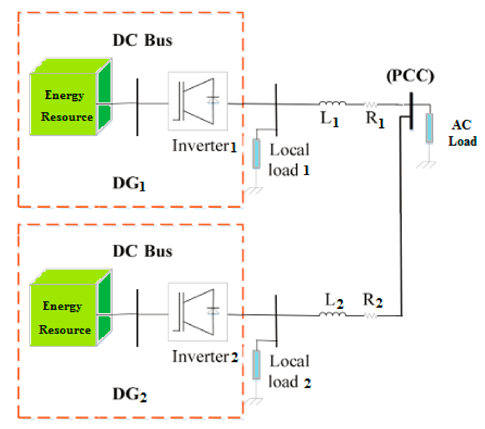
2. Formulations of Operation Principle

Figure 2 shows a block diagram of a typical MG consisting of several DGs connected to a point of common coupling (PCC) to feed the total demand loads. Each DG is equipped with a local control and transmits the generated DC power to the upstream network or to the loads, through passing the output LC filter. This low-pass filter (LPF) used in this scheme is also designed to eliminate the harmful high-order harmonics. The feeder impedance is then represented by r l + j x l to model the cable or line voltage drop.
The main block diagram of the control scheme is shown is Figure 3 for just one DG considering the power sharing and the voltage control loops. In this way, the sampling signals are obtained from output voltage ( v o ) and output current ( i o ) in order to model the load characteristics, which are transferred to P/Q calculation block to determine how much power is required. Then the droop control is applied and in the voltage control loop, a classic proportional-integrator (PI) controller is hired to mitigate the voltage distortions. The classic droop control makes a lot of drawbacks explained in the previous section and these have motivated the authors to propose a novel SMC approach to overcome the difficulties.
The equivalent circuits of a DG for both grid-connected and islanding modes are represented in Figure 4. In an islanding operation mode, the main dynamic equations proposed for the DG behavior are mathematically formulated in (1).
d d t i L f = K P W M v i v o i L f R f L f d d t v o = i L f i o C f
where R f , L f and C f are the output filter resistance, inductance and capacitance, respectively. v i represents the input control signal and K P W M is the corresponding model of switching pattern considering the modulation index and Finally, i L f expresses the inductive part of filter current. Using some simplifications in Equation (1) leads to:
d 2 d t 2 v o = K P W M v i L f C f v o L f C f R f i L f L f C f + R f L f d v o d t 1 C f d i o   d t
Which is compatible with the diagram represented in Figure 4a.
In an islanding operation mode, the time-dependent equation of dynamic performance is represented in (3), where v s d represents the AC voltage distortions.
d d t i o = K P W M v i v s v s d i o R f L f

3. Control Approach

A simplified equivalent circuit of two DGs operating in parallel is represented in Figure 5, where their output voltages are E i ϕ i   i = 1 ,   2 and ϕ i is the voltage phase angle of each DG. The feeder impedance is notated with r k + j X k   k = 1 ,   2 and the load integrated with AC grid is shown by R + j X with voltage U 0 .
Therefore, the active and reactive power supplied by each DG is determined in (4), respectively.
P i = 1 Z i U E i cos ϕ i U 2 cos θ i + U E i sin ϕ i sin θ i Q i = 1 Z i U E i cos ϕ i U 2 sin θ i + U E i sin ϕ i cos θ i
where
Z i = r i + j X i Z i = r i 2 + X i 2 θ i = tan 1 X i r i
Since the inverter impedance is assumed to be resistive and the inductive part is negligible, Equation (4) can be simplified to (6).
P i = 1 r i U E i cos ϕ i U 2 Q i = 1 r i U E i sin ϕ i
As mentioned in introduction section, the resistive droop controller is structured in (7).
E i = E i * + m P i * P i f i = f i * n 2 π Q i * Q i
where E i * and f i * are the rated voltage and frequency of the system and the droop constants are called m and n . In closed loop equivalent circuit of grid connected operation mode, the main purpose is to achieve good power sharing and load current tracking, because the system voltage and frequency references are supplied by the upstream network. Then the principal system equation is mathematically formulated in (8).
d d t i o = R f L f i o + K P W M v i L f v s L f + m t
Since we want to analyze the general form of system equation, it should be converted to (9).
d d t x g c t = a   x g c t + b   u t + c   z t + m t
where the parameters a , b and c are determined by comparing (8) and (9). m t is a bounded distortion applied to the system where m t < δ , and δ is a positive constant. The error of current tracking is described as e g c = i o i r e f . Therefore, the dynamic sliding surface can be expressed as follow:
S g c t = e g c t + k 1 0 t e g c t d t + k 2 d e g c t d t d d t S g c t = d e g c t d t + k 1 e g c t + k 2 d 2 e g c t d t 2
The coefficients k 1 and k 2 are positive and the control law is defined as:
u = u o + u s w u o = b 1 ( c p v s + a + k 1 e g c + k 2 d 2 e g c t d t 2 + a   i r e f d i r e f d t u s w = b 1   Υ ^ t s i g n S g c t
where u o is the control parameter related to the system specifications and u s w represent the switching control model. The system stability analysis is reported in the next section, however, the observative gain of the system is approximated by (12).
  Υ ^ t = 1 ξ g c S g c t d t + S g c t
where ξ g c is a positive constant.
Subsequently, since the DG is operating in islanding operation mode, the main purpose of control system is to supply the rated voltage and frequency in the allowable range. According to this definition, the main system equation is expressed as:
d 2 d t 2 v o = R f L f d v o d t v o L f C f + K P W M v i L f C f + n t
and in general form, we can re-write this equation to (14).
d 2 d t 2 x i s l t = d d d t x i s l t + f   x i s l t + g   u t + n t
where the parameters d , f and g are determined by comparing (8) and (9). n t is a bounded distortion applied to the system where n t < σ , and σ is a positive constant. Since the voltage tracking error is e i s l = v o v r e f , the three order sliding surface could be introduced as (15).
S i s l t = k 4 e i s l t + k 3 0 t e i s l t d t + d e g c t d t d d t S i s l t = k 3 e i s l t + k 4 d e i s l t d t + d 2 e i s l t d t 2
where k 3 and k 4 are positive constants. In this way, the switching control law is defined as follow:
u = u t + u s w u r = g 1 ( f v o + k 3 e g c d 2 v r e f d t 2 + d d v o d t + k 4 d i r e f d t u s w = g 1   Θ ^ t s i g n S g c t
where   Θ ^ t = 1/ ξ i s l S i s l t d t + S i s l t and ξ i s l is a positive constant. In order to modify the stability of the controller, these modifications can be applied to the conventional equations:
E i = E i * + m P i * P i m Q i * Q i f i = f i * n 2 π Q i * Q i + n 2 π P i * P i
Using low pass filter (LPF) and Laplace transform to Equation (4), and some simplifications considering the feeder impedance effect, it could be derived that:
P i ^ = ω c s + ω c U r i E ^ i cos ϕ i ϕ ^ i E i sin ϕ i Q i ^ = ω c s + ω c U r i E ^ i sin ϕ i + ϕ ^ i E i cos ϕ i
E ^ i = m P i ^ + n E i X f e e d e r r i Q i ^ f ^ i = n 2 π Q i ^ m X f e e d e r E i r i P i ^
and finally, the closed loop three order system, equation is achieved in (20).
s 3 + s 2 2 ω c + U ω c m cos ϕ i r i + U ω c n E i sin ϕ i X f e e d e r r i 2 + s ω c 2 + n E i + m ω c U ω c cos ϕ i r i + n E i ω c m U ω c sin ϕ i X f e e d e r r i 2 + cos ϕ i r i + m U n U ω c 2 r i 2 + r i 2 + n U E i X f e e d e r m U ω c 2 X f e e d e r r i 4 = 0

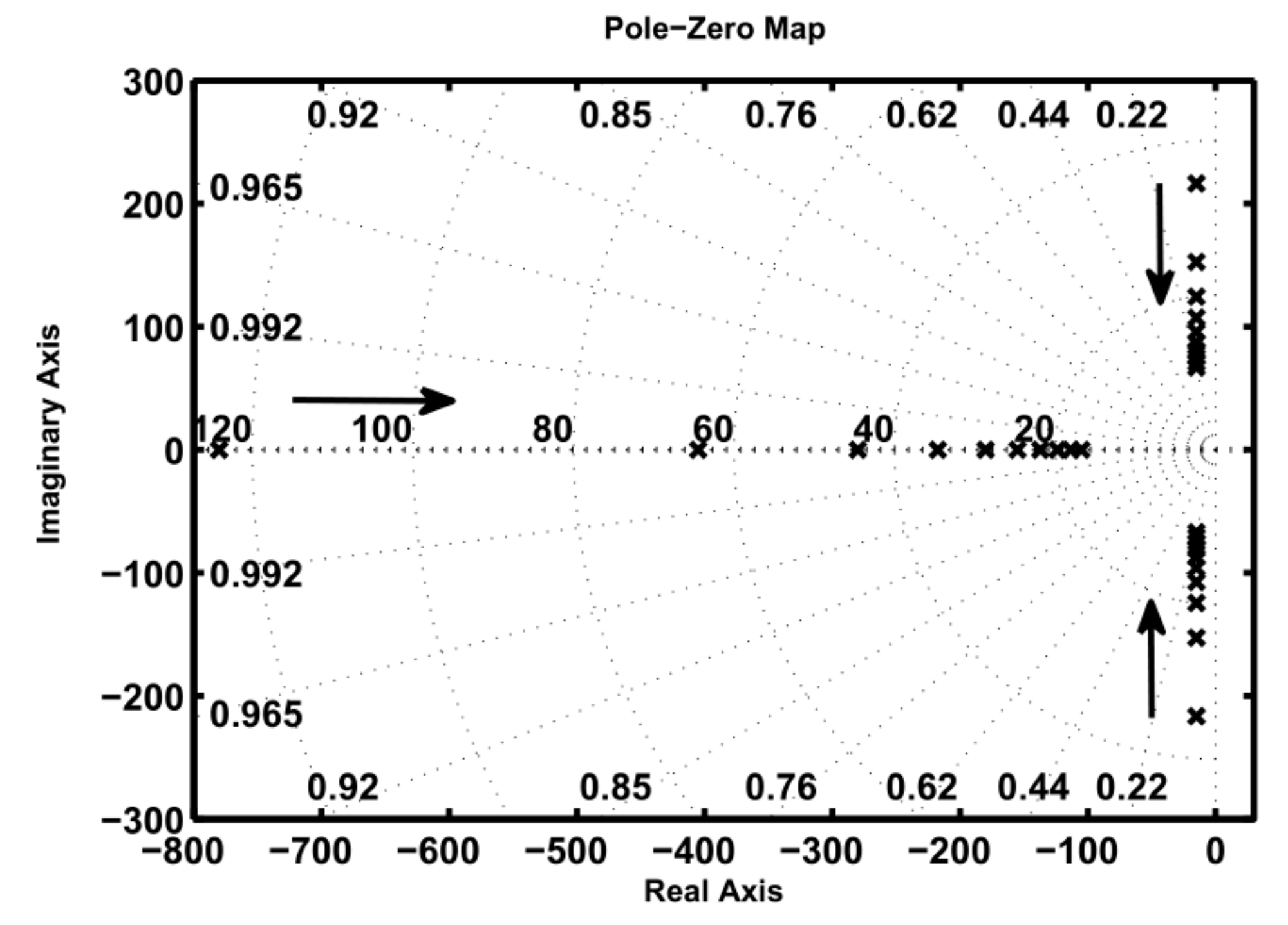
4. Stability Evaluation

This section is divided into two subsections to represent the stability of proposed method.

4.1. Grid-Connected Mode

The Lyapunov function is considered to be:
V g c S ,   Υ ˜ = 1 2   S 2 + 1 2   ξ g c   Υ ˜ 2
where the subscript g c denotes the grid-connected operation mode and we have:   Υ ˜ = Υ   Υ ^ . The first order derivative of Lyapunov function results in:
d d t V g c S t ,   Υ ˜ t = S t d d t S t +   ξ g c   Υ ˜ t d d t   Υ ˜ t
and according to (9) to (12), we have:
d d t V g c S t ,   Υ ˜ t = S t g p u s w + n t +   ξ g c Υ t   Υ ^ t d d t   Υ ˜ t = S t   Υ ^ t s i g n S t + n t ξ g c Υ t   Υ ^ t S t ξ g c = S t n t Υ t S t S t n t Υ t 0
Therefore, the control approach is stable in grid connected operation mode.

4.2. Islanding Mode

In this way, the Lyapunov function could be assumed as:
V i s l S i s l ,   Θ ˜ = 1 2   S i s l 2 + 1 2   ξ i s l   Θ ˜ 2
Corresponded to the pervious subsection, the subscript ‘ i s l ’ represents the islanding operation mode and for the uncertainties, we should have:   Θ ˜ = Θ   Θ ^ . So that, the first order derivative is mathematically calculated as:
d d t V i s l S i s l t ,   Θ ˜ t = S i s l t d d t S i s l t +   ξ i s l   Θ ˜ t d d t   Θ ˜ t
where according to (13) to (16), we have:
d d t V i s l S i s l t ,   Θ ˜ t = S i s l t b p u g s w + m t +   ξ i s l Θ t Θ t d d t   Θ ˜ t = S i s l t   Θ ^ t s i g n S i s l t + m t ξ i s l Θ t Θ t S t ξ i s l = S i s l t m t Θ t S i s l t S i s l t m t Θ t 0
Therefore, the control approach is stable is islanding operation mode.

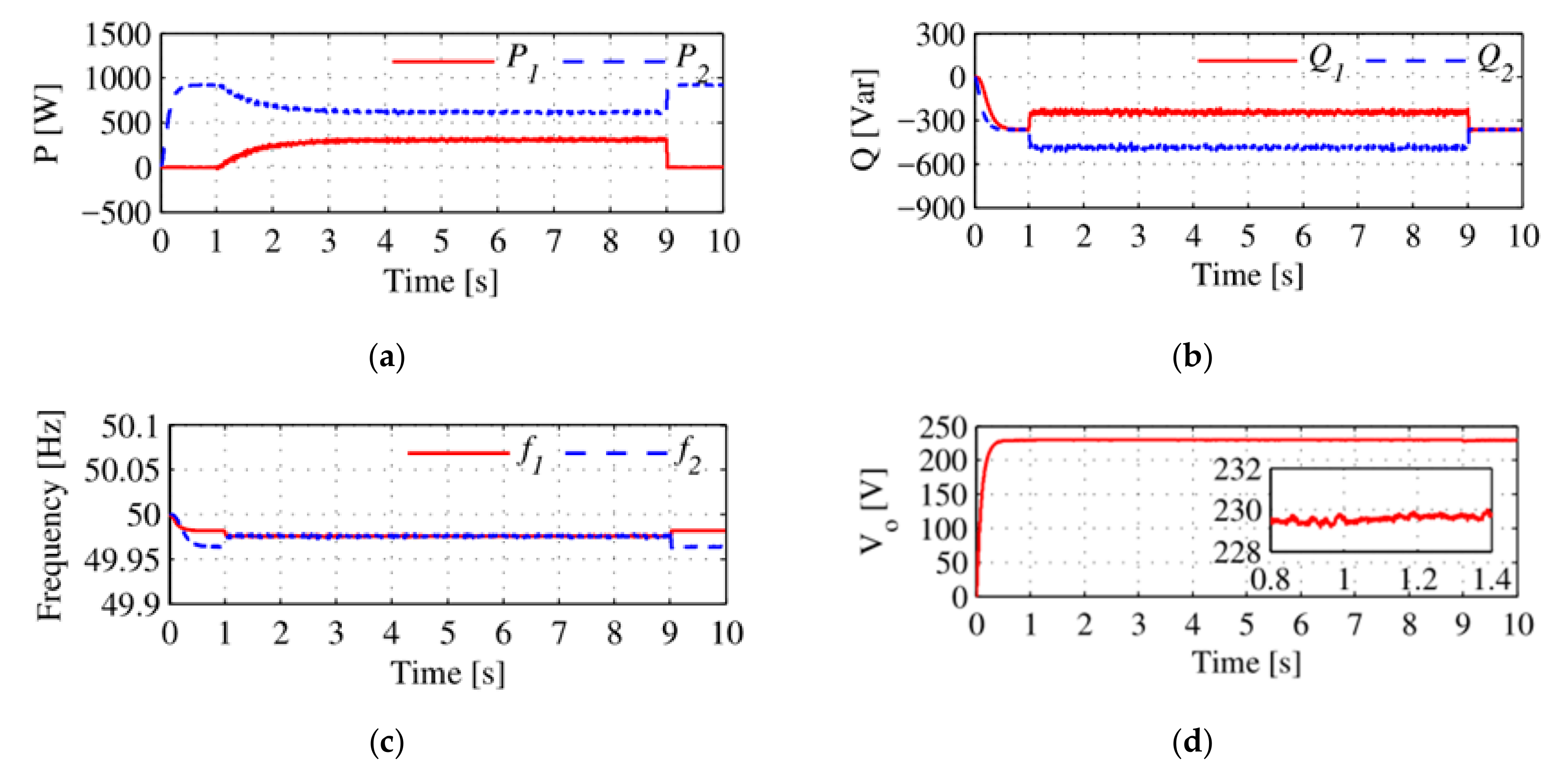
5. Simulations Results

The proposed control strategy has been implemented on the MG shown in Figure 6, including two DGs with two local loads and one AC load connected to the PCC. Both DGs have to procure the active and reactive demands, required by the local loads and the AC load, which is assumed to be supplied according to their nominal capacity. This results in there not being overloading for all the DGs contributed to the power sharing issue. The system specifications and control parameters are represented in Table 1 and Table 2, respectively. The root locus map of the transfer function of proposed control system is presented in Figure 7, which implies on the system stability based on roots movement in terms of ξ g c variation in grid-connected operation mode.
The simulation results are conducted out in three scenarios. In all of scenarios, the proposed control approach is applied to the system at t = 1   s to t = 9   s , where the accurate power sharing is obtained. The total load connected to the MG is 900   W j 750   Var , in which the two DGs are arranged to supply it. Since the apparent power of DG2 is twice than DG1, it is expected that the power sharing is achieved with ratio of 2:1. It means that if the total load is divided into three parts, two of them should be procured by DG2 and the remained load has to be supplied by DG1.
Due to the significant effect of feeder impedance in power sharing issue, there are three different feeder impedances considered in the MG for both DGs. At the first scenario, it is assumed that the feeder impedance is completely inductive and the resistive part is neglected. The results of this scenario are represented in Figure 8, where in Figure 8a, the active powers are shared in the aforementioned ratio of 2:1, as well as the reactive powers shown in Figure 8b. The frequency of each DG and their terminal output voltages are represented in Figure 8c,d, that they are kept constant in their permissible range.
As soon as the feeder impedance are varied to totally resistive, the results are obtained in Figure 9, where the accurate power sharing without no errors is achieved. Even if the impedance feeder is assumed to be complex, the results do not change any more as shown in Figure 10. These scenarios are chosen to signify that the proposed approach can make a precise power sharing independent to feeder impedance variation. It is worth mentioning that for all scenarios, these results are obtained:
P 2 = 2 2 + 1 900 = 600 W P 1 = 1 2 + 1 900 = 300 W Q 2 = 2 2 + 1 750 = 500   V a r Q 1 = 1 2 + 1 750 = 250   V a r

6. Discussion

The comparisons made for proposed approach and conventional SMC, is represented in Table 3 and Table 4, to show the effectiveness of 3rd order SMC integrated with droop controller. As can be seen in these tables, the settling time in the proposed controller is less than the conventional mode. This indicates that using the proposed method, we will obtain the final answer faster. Less overshoot in the proposed control method specifies that the uplift rate compared with steady state response is less than the conventional mode and there is less noise in the system. Similarly, it can be seen that shorter rise time increases the speed of reaching the final solution, which is observed in the proposed controller. Comparison of these parameters with the traditional controller indicates the superiority of the proposed method.

7. Conclusions

This paper has recommended a novel technique based on droop control approach for precise power sharing among the parallel DGs in MGs. Since the differences in the impedance of the feeder causes an error in the reactive power sharing and increases the error, it will also cause an unequal voltage in the output terminal of the DGs. In this paper, the effect of different types of feeder impedances was investigated and the simulation results indicate that changes in this parameter (Zline) do not affect the power sharing accuracy. Furthermore, reactive power sharing using feeder impedance compensation is proposed in the modified SMC algorithm, which allows the terminals voltage of each inverter to maintain itself, especially in the off-grid mode. The stability of the frequency and optimal active power sharing is the other results of the proposed scheme. Since the droop method is simple and can be implemented on a laboratory setup, the authors will analyze the coding of the proposed SMC method based on droop based on future works.

Author Contributions

A.S.-A., conceptualization and methodology; M.M., software and validation; A.G., investigation and analysis; E.P., review and editing. All authors have read and agreed to the published version of the manuscript.

Funding

This research received no external funding.

Institutional Review Board Statement

The study was conducted according to the guidelines of the Islamic Azad University of Iran, and approved by the Institutional Review Board of Department of Engineering in Marvdasht branch.

Informed Consent Statement

Informed consent was obtained from all subjects involved in the study.

Conflicts of Interest

The authors declare no conflict of interest.

References

  1. García, V.Y.E.; Dufo, L.R.; Bernal, A.J.L. Energy Management in Microgrids with Renewable Energy Sources: A Literature Review. Appl. Sci. 2019, 19, 3854. [Google Scholar] [CrossRef] [Green Version]
  2. Bazmohammadi, N.; Anvari-Moghaddam, A.; Tahsiri, A.; Madary, A.; Vasquez, J.C.; Guerrero, J.M. Stochastic Predictive Energy Management of Multi-Microgrid Systems. Appl. Sci. 2020, 10, 4833. [Google Scholar] [CrossRef]
  3. Mehrasa, M.; Pouresmaeil, E.; Soltani, H.; Blaabjerg, F.; Calado, M.; Catalão, J.P. Virtual Inertia and Mechanical Power-Based Control Strategy to Provide Stable Grid Operation under High Renewables Penetration. Appl. Sci. 2019, 9, 1043. [Google Scholar] [CrossRef] [Green Version]
  4. Hou, X.; Sun, Y.; Yuan, W.; Han, H.; Zhong, C.; Guerrero, J.M. Conventional P-ω/QV Droop Control in Highly Resistive Line of Low-Voltage Converter-Based AC Microgrid. Energies 2016, 9, 943. [Google Scholar] [CrossRef] [Green Version]
  5. Tayab, U.B.; Bin, R.M.A.; Hwai, L.J.; Kashif, M. A Review of Droop Control Techniques for Microgrid. Renew. Sustain. Energy Rev. 2017, 76, 717–727. [Google Scholar] [CrossRef]
  6. Sun, Y.; Hou, X.; Yang, J.; Han, H.; Su, M.; Guerrero, J.M. New Perspectives on Droop Control in AC Microgrid. IEEE Trans. Ind. Electron. 2017, 64, 5741–5745. [Google Scholar] [CrossRef] [Green Version]
  7. Vu, T.V.; Perkins, D.; Diaz, F.; Gonsoulin, D.; Edrington, C.S.; El-Mezyani, T. Robust Adaptive Droop Control for DC Microgrids. Electr. Power Syst. Res. 2017, 146, 95–106. [Google Scholar] [CrossRef] [Green Version]
  8. Peyghami, S.; Davari, P.; Mokhtari, H.; Blaabjerg, F. Decentralized Droop Control in DC Microgrids Based on a Frequency Injection Approach. IEEE Trans. Smart Grid 2019, 10, 6782–6791. [Google Scholar] [CrossRef] [Green Version]
  9. Peng, Z.; Wang, J.; Bi, D.-Q.; Wen, Y.; Dai, Y.; Yin, X.; Shen, J. Droop Control Strategy Incorporating Coupling Compensation and Virtual Impedance for Microgrid Application. IEEE Trans. Energy Convers. 2019, 11, 1. [Google Scholar] [CrossRef]
  10. Yuan, W.; Wang, Y.; Liu, D.; Deng, F.; Chen, Z. Efficiency-Prioritized Droop Control Strategy of AC Microgrid. IEEE J. Emerg. Sel. Top. Power Electron. 2020, 1. [Google Scholar] [CrossRef]
  11. Wang, R.; Sun, Q.; Gui; Y; Ma, D. Exponential-Function-Based Droop Control for Islanded Microgrids. J. Mod. Power Syst. Clean Energy 2019, 7, 899–912. [Google Scholar] [CrossRef] [Green Version]
  12. Wang, S.; Lu, L.; Han, X.; Ouyang, M.; Feng, X. Virtual-Battery Based Droop Control and Energy Storage System Size Optimization of a DC Microgrid for Electric Vehicle Fast Charging Station. Appl. Energy 2020, 259, 114146. [Google Scholar] [CrossRef]
  13. Matayoshi, H.; Kinjo, M.; Rangarajan, S.S.; Ramanathan, G.G.; Hemeida, A.M.; Senjyu, T. Islanding Operation Scheme for DC Microgrid Utilizing Pseudo Droop Control of Photovoltaic System. Energy Sustain. Dev. 2020, 55, 95–104. [Google Scholar] [CrossRef]
  14. Bijaieh, M.M.; Weaver, W.W.; Robinett, R.D., III. Energy Storage Requirements for Inverter-Based Microgrids under Droop Control in dq Coordinates. IEEE Trans. Energy Convers. 2019, 11, 611–620. [Google Scholar]
  15. Shi, Z.; Li, J.; Nurdin, H.I.; Fletcher, J. Comparison of Virtual Oscillator and Droop Controlled Islanded Three-Phase Microgrids. IEEE Trans. Energy Convers. 2019, 34, 1769–1780. [Google Scholar] [CrossRef]
  16. Espina, E.; Cardenas, R.; Espinoza-B., M.; Burgos-Mellado, C.; Sáez, D. Cooperative Regulation of Imbalances in Three-Phase Four-Wire Microgrids Using Single-Phase Droop Control and Secondary Control Algorithms. IEEE Trans. Power Electron. 2020, 35, 1978–1992. [Google Scholar] [CrossRef]
  17. Du, W.; Chen, Z.; Schneider, K.P.; Lasseter, R.H.; Nandanoori, S.P.; Tuffner, F.K.; Kundu, S. A Comparative Study of Two Widely Used Grid-Forming Droop Controls on Microgrid Small-Signal Stability. IEEE J. Emerg. Sel. Top. Power Electron. 2020, 8, 963–975. [Google Scholar] [CrossRef]
  18. Wang X, X.; Zhang, J.; Zheng, M.; Ma, L. A Distributed Reactive Power Sharing Approach in Microgrid with Improved Droop Control. CSEE J. Power Energy Syst. 2020, 1–9. [Google Scholar] [CrossRef]
  19. Hosseinimoghadam, S.M.S.; Roghanian, H.; Dashtdar, M.; Razavi, S.M. Power-Sharing Control in an Islanded Microgrid using Virtual Impedance. In Proceedings of the 8th International Conference on Smart Grid (icSmartGrid), Paris, France, 17–19 June 2020; pp. 73–77. [Google Scholar] [CrossRef]
  20. Mahmoudian, M.; Bian, M.A.; Gitizadeh, M. High Accuracy Power Sharing in Parallel Inverters in an Islanded Microgrid Using Modified Sliding Mode Control Approach. Sci. Iran. 2019, 1. [Google Scholar] [CrossRef] [Green Version]
  21. Maanavi, M.; Najafi, A.; Godina, R.; Mahmoudian, M.; Rodrigues, E.M.G. Energy Management of Virtual Power Plant Considering Distributed Generation Sizing and Pricing. Appl. Sci. 2019, 9, 2817. [Google Scholar] [CrossRef] [Green Version]
  22. De Machado, S.J.M.M.; Silva, S.A.O.D.; Monteiro, J.R.B.D.A.; de Oliveira, A.A. Network Modeling Influence on Small-Signal Reduced-Order Models of Inverter-Based AC Microgrids Considering Virtual Impedance. IEEE Trans. Smart Grid 2021, 12, 79–92. [Google Scholar] [CrossRef]
  23. Pham, D.M.; Lee, H.H. Effective Coordinated Virtual Impedance Control for Accurate Power Sharing in Islanded Microgrid. IEEE Trans. Ind. Electron. 2020, 68, 2279–2288. [Google Scholar] [CrossRef]
Figure 1. A smart microgrid (MG) considering smart equipment.
Applsci 11 00967 g001
Figure 2. Block diagram of a typical MG consisting of several distributed generations (DGs).
Applsci 11 00967 g002
Figure 3. Block diagram of the DG control scheme.
Applsci 11 00967 g003
Figure 4. The equivalent circuits of a DG; (a) grid-connected mode, (b) islanding mode.
Applsci 11 00967 g004
Figure 5. A simplified equivalent circuit of two DGs operating in parallel.
Applsci 11 00967 g005
Figure 6. The MG under consideration.
Applsci 11 00967 g006
Figure 7. The pole-zero map of proposed control system.
Applsci 11 00967 g007
Figure 8. Power sharing in the first scenario considering inductive feeder impedance; (a) output active powers of DGs, (b) output reactive powers of DGs, (c) output frequencies of DGs, (d) terminal DGs voltage.
Applsci 11 00967 g008
Figure 9. Power sharing in the first scenario considering resistive feeder impedance; (a) output active powers of DGs, (b) output reactive powers of DGs, (c) output frequencies of DGs, (d) terminal DGs voltage.
Applsci 11 00967 g009
Figure 10. Power sharing in the first scenario considering complex (R-L) feeder impedance; (a) output active powers of DGs, (b) output reactive powers of DGs, (c) output frequencies of DGs, (d) terminal DGs voltage.
Applsci 11 00967 g010
Table 1. System specifications.
ParameterValue
AC   grid   voltage   (   V A C )400 (V, rms)
AC   grid   frequency   ( f A C )50 (Hz)
Switching   frequency   (   f s w )15 (kHz)
Input   DC   voltage   (   V d c ) for both DGs500 (V)
Filter   resistance   (   R f ) for DG1 62   ( m Ω )
Filter   resistance   (   R f ) for DG2 48   ( m Ω )
Filter   inductance   (   L f ) for DG1 2.2   ( m H )
Filter   inductance   (   L f ) for DG2 2.1   ( m H )
Filter   capacitance   (   L f ) for DG1 220   ( μ F )
Filter   capacitance   (   L f ) for DG2 220   ( μ F )
Rated   Power   (   S n o m i n a l ) for DG14 (kVA)
Rated   Power   (   S n o m i n a l ) for DG28 (kVA)
Feeder   impedance   (   Z f e e d e r ) for DG1 35   +   j 10   ( m Ω )
Feeder   impedance   (   Z f e e d e r ) for DG1 44   +   j 16   ( m Ω )
Table 2. Control parameters.
ParameterValue
Active droop coefficients (m) for DG14.26 × 10−4 (V/W)
Active droop coefficients (m) for DG27.63 × 10−4 (V/W)
Reactive droop coefficients (n) for DG13.04 × 10−4 (rad/s/Var)
Reactive droop coefficients (n) for DG26.08 × 10−4 (rad/s/Var)
Cut-off frequency (   ω c ) for both DGs10 (rad/s)
ξ g c 1000
ξ i s l 800
Table 3. Performance comparison of studied method for active power.
MethodScenario 1Scenario 2Scenario 3
Rise TimeOvershootSettling TimeRise TimeOvershootSettling TimeRise TimeOvershootSettling Time
Conventional SMC0.0051 s3.17%0.075 s0.0128 s3.12%0.065 s0.0086 s3.04%0.059 s
Proposed MSMC0.0035 s1.24%0.042 s0.0096 s1.34%0.036 s0.0075 s1.16%0.027 s
Table 4. Performance comparison of studied method for reactive power.
MethodScenario 1Scenario 2Scenario 3
Rise TimeOvershootSettling TimeRise TimeOvershootSettling TimeRise TimeOvershootSettling Time
Conventional SMS0.0075 s3.16%0.078 s0.0123 s3.23%0.068 s0.008 s3.27%0.063 s
Proposed MSMC0.0051 s1.33%0.053 s0.0076 s1.22%0.031 s0.007 s1.05%0.020 s
Publisher’s Note: MDPI stays neutral with regard to jurisdictional claims in published maps and institutional affiliations.

