Abstract
In nonlinear analysis for performance-based design of reinforced concrete moment frames, a plastic hinge spring element is predominantly used in order to simply and accurately describe the inelastic behavior of beam–column joints, including strength degradation. Although current design codes and guidelines provide various beam–column joint models, the focus is on concentric beam–column joints. Therefore, more studies are required for eccentric beam–column joints, which are also common in practice. In the present study, to consider the effect of beam eccentricity on the behavior of beam–column joints, a simplified plastic hinge model was proposed using the effective joint width of current design codes. The proposed model was compared to the cyclic loading test results of beam–column joints with/without beam eccentricity. The comparison showed that the simplified plastic hinge model with the effective joint width of NZS 3101-2006 or Eurocode 8 is considered acceptable for design purpose.
1. Introduction
For a safe and cost-effective design of building structures, the performance-based earthquake design is widely used. For the design approach, nonlinear behavior of structural components should be well described in analysis, including deformation capacity. In the case of reinforced concrete (RC) moment frames, the deformation capacity is significantly affected by shear damage and bar-slip at beam–column joints [1,2,3,4,5,6,7,8,9,10,11], and the joint shear damage and bar-slip are unavoidable even if the requirements of current seismic design codes [12,13,14,15] for beam–column joints are satisfied. Thus, to achieve a reliable design of RC moment frames, those characteristics affecting the nonlinear behavior of beam–column joints should be carefully considered in the analysis.
In practice, a lumped plastic hinge spring element is predominantly used for beam–column joints, because it is available in most of commercial software for nonlinear analysis [16,17]. Thus, it is reasonable to reflect those characteristics in the plastic hinge spring element. Meanwhile, joint shear strength degradation is also critical to the deformation capacity of beam–column joints. To address the nonlinear behavior of beam–column joints, a vast number of studies have been conducted: idealizing models, such as the strut–tie mechanism-based models [7,8,9,10,18,19,20] and the rotating-angle softened-truss model [21], and empirical equations [12,22,23] were proposed; the strain-increase in beam flexural bars due to cyclic loads was considered in the prediction of the joint shear strength degradation and deformation capacity [6]; the effects of joint shear demand, joint hoop bars, and yield strength of beam flexural bars on the joint deformation capacity were considered [24]; the effects of bar-slip, bar elongation, diagonal cracking, and shear deformation on the joint shear strength degradation were studied [8]; and the joint shear strength was defined as a function of target lateral drift ratio [9,10]. Although the existing studies provide a deep understanding on the behavior of beam–column joints, the majority of the existing studies focused on concentric beam–column joints. However, eccentric beam–column joints, in which the axis of beams framing into a joint does not lie on the column centerline, are also common in practice.
To investigate the effect of eccentric beams on the joint shear strength, several experimental studies were performed, and it was found that as the beam eccentricity increased, the shear strength capacity and ductility were decreased at interior [25,26,27,28,29,30,31] and exterior [32,33,34] beam–column joints. To consider the degradation in the shear strength of eccentric beam–column joints, a simple method of reducing the effective joint width was also proposed [27,28]. On the other hand, it was found that slabs can alleviate the shear strength degradation of eccentric beam–column joints [35,36]. Although the existing studies investigated the joint shear strength of eccentric beam–column joints, the deformation capacity and strength degradation were not evaluated, which were necessary for nonlinear analysis modeling.
Recently, for an improved performance-based design, Hwang and Park [37] developed an advanced plastic hinge model, which is applicable to interior and exterior beam–column joints. In the model, the effects of beam bar-slip and joint shear strength degradation were taken into account covering various design parameters, and the joint shear deformation and beam flexural deformation were also combined for simple modeling and computation. However, the existing models, including the model of Hwang and Park [37], were developed primarily for concentric beam–column joints. Thus, more studies are required for eccentric beam–column joints, considering the facts that a considerable number of RC structures are designed to have eccentric beam–column joints in practice and the design of RC structures is subjected to seismic and dynamic influences.
In the present study, for a safer and more economical design of RC structures, the effect of beam eccentricity on the behavior of beam–column joints was investigated. To this purpose, the effective joint width of current design codes and the plastic hinge model of Hwang and Park [36] were utilized with a modification, which can describe the nonlinear behavior of eccentric beam–column joints. For verification, the proposed method was compared to existing test results available in the literature.
2. Current Design Codes for Effective Joint Width
Current design codes, such as ACI 318-19 [12], ACI 352R-02 [13], and NZS 3101-2006 [14], specify the effective joint width bs for concentric and eccentric beam–column joints (Figure 1). On the other hand, Eurocode 8 [15] does not consider the beam eccentricity in calculation of the effective joint width.
where bb is the beam width; hc is the column depth; bc is the column width; x is the smaller distance between the beam and column edges; m = 0.3 when the eccentricity e is greater than bc/8 or m = 0.5 otherwise; and e is the eccentricity between the beam and column centerlines. In Equation (2), the value of mhc/2 is limited to the distance between the beam and column edges at each side.
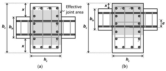
Figure 1.
Effective joint area: (a) concentric beam–column joint; (b) eccentric beam–column joint.
Figure 2 compares the effective joint width bs calculated by the current design codes (Equations (1)–(4)). As shown in the figure, for concentric beam–column joints (Figure 2a), the effective joint width was increased with the increase in the column width, and ACI 352R-02 [13] provided the smallest estimation. On the other hand, for eccentric beam–column joints (Figure 2b with x = 0), Eurocode 8 [15] ignoring the beam eccentricity provided the largest estimation, while ACI 318-19 [12] having a limitation of x = 0 provided the smallest estimation. As compared in Figure 2c, the effective joint width was decreased as the beam eccentricity increased (except Eurocode 8 [15]), and ACI 352R-02 [13] provided a smaller effective joint width than NZS 3101-2006 [14].
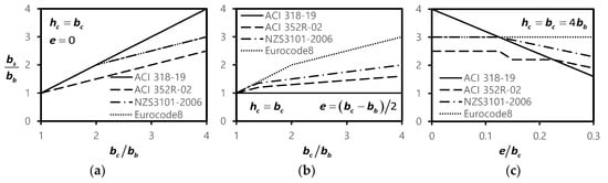
Figure 2.
Comparison of effective joint widths in current design codes: (a) concentric beam–column joint; (b) eccentric beam–column joint; (c) effect of beam eccentricity.
3. Joint Shear Strength Degradation Model
Hwang and Park [37] proposed a simplified plastic hinge model for interior and exterior beam–column joints, which could predict the lateral load–drift ratio relationship, including strength degradation. Figure 3 shows the plastic hinge model for interior and exterior beam–column joints [37,38]. In the model, a joint is simplified using elastic beam–column elements, rotational spring elements, and rigid elements. The elastic beam–column elements are used to represent the elastic flexural deformation of beams and columns along their net length. The rigid elements are located at the center of the joint panel, and the rotational spring elements connect the beam–column elements and rigid elements at the joint interface and represent the sum of elastic joint shear deformation, plastic joint shear deformation, and plastic beam deformation.
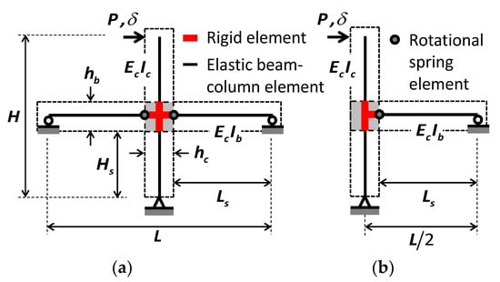
Figure 3.
Plastic hinge model for beam–column joints: (a) interior beam–column joint; (b) exterior beam–column joint.
3.1. Lateral Load–Drift Ratio Relationship
Figure 4a shows the envelop curve of the simplified plastic hinge model [37] for a joint, and EY, EU, and EF in the figure indicate the yield, ultimate, and failure points, respectively. In the model, the lateral load Py at EY corresponds to the nominal moment strength of the beam section at the joint interface. The lateral drift ratio δy at EY includes the elastic deformations of beams and columns framing into the joint (affected by effective flexural stiffness EI) and elastic joint shear deformation of the joint panel (affected by the rotation angle θjy [22]).
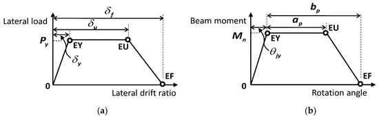
Figure 4.
Load–displacement relationship of plastic hinge model: (a) lateral load–drift relationship of beam–column joint; (b) moment–rotation relationship of plastic hinge.
For interior beam–column joints,
For exterior beam–column joints,
where L is the beam length; H is the column height; Hs is the column shear span; Ls is the beam shear span; hb is the beam height; M+ and M− are the positive and negative moments of the beam section, respectively; As and As′ are the areas of tension and compression bars in the beam section, respectively; Ah and fyh are the area and yield strength of joint hoop bars parallel to beam flexural bars, respectively; and fc’ is the concrete compressive strength.
According to ASCE/SEI 41-17 [16], the effective flexural stiffness of beams (EcIb) and columns (EcIc) are defined as follows:
where Ec is the elastic modulus of concrete (= 4700√fc’); Igb and Igc are the second-order moments of inertia for gross section of beams and columns, respectively; and Nc is the axial force in columns.
The lateral drift ratios δu and δf at EU and EF are defined as follows:
where ap (= aj + af) and bp (= bj + bf) are the plastic hinge rotation angles of a rotational spring element at EU and EF (Figure 4b), which represent the sum of the joint plastic shear angle and beam plastic rotation. The definitions of aj, af, bj, and bf are given in the following section.
3.2. Plastic Hinge Model
3.2.1. Ultimate Point
According to Hwang and Park [37], the joint plastic shear angle aj is defined as follows:
For interior beam–column joints,
For exterior beam–column joints,
where αc is the strength increment factor due to the confinement effect of cross-beams (Figure 5); βc is the compression zone depth ratio; βj is the joint configuration ratio (= hb/hc); κ is the energy dissipation ratio of beam–column joints; ldh is the development length of beam flexural bars anchored into the joint; and db is the diameter of beam bottom bars. Note that in the calculation of amj, the initial value of aj is used without consideration of the limitation of amj.
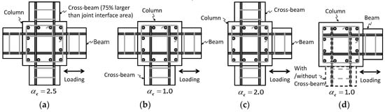
Figure 5.
Confinement of beam–column joints: (a) interior beam–column joint with two-cross beams; (b) interior beam–column joint without two-cross beams; (c) exterior beam–column joint with two-cross beams; (d) exterior beam–column joint without two-cross beams.
On the other hand, the beam plastic rotation angle af is defined as a function of the energy dissipation ratio κ. [8,9,10,37]
where amf is the maximum plastic rotation angle in order to consider the beam failure (= 0.003 to 0.025 rad) [16,37].
3.2.2. Failure Point
The joint plastic shear angle bj is defined as follows, assuming linear strength degradation from EU to the point corresponding to 90% of the peak strength [37].
For interior beam–column joints,
For exterior beam–column joints,
In this study, to avoid the overestimation of deformation capacity in building structures and to address the minimum increase in the joint plastic shear angle, the joint plastic shear angle bj was simplified as follows:
On the other hand, the beam plastic rotation angle bf is defined as a function of the energy dissipation ratio κ [8,9,10,37].
where bmf is the maximum plastic rotation angle in order to consider the beam failure (= 0.01 to 0.05 rad) [16,36].
3.2.3. Summary of Parameters for Plastic Hinge Model
For modeling of the load–displacement relationship, the lateral load and drift ratios at point EY are determined from Equations (5) and (6) for interior beam–column joints (or Equations (8) and (9) for exterior beam–column joints), respectively. The drift ratios at points EU and EF are determined from Equations (15) and (16), respectively, and the lateral load at point EU is the same as that at point EY. The parameters for the plastic rotation angles used in Equations (15) and (16) are summarized in Table 1.

Table 1.
Parameters for plastic rotation angles.
4. Application of Simplified Plastic Hinge Model
4.1. Existing Test Results
To verify the simplified plastic hinge model, existing test results available in the literature were collected. Among those test results, cyclic loading tests for interior [25,30] and exterior [31,32,34] beam–column joints were used to compare predictions (envelope curves) with measurements (cyclic responses). Table 2 summarizes the primary test parameters of the test specimens. It is noted that the eccentricity ratio of beams e/bc was in the range of 0–1/4, and the axial load ratio of columns (Nc/fc’bchc) was in the range of 0–0.20 in the collected test specimens.
Table 2.
Test parameters of existing beam–column joint test specimens.
In the application of the simplified plastic hinge model, the effective joint widths of the current design codes [12,13,14,15] were used. Table 3 compares the calculated effective joint widths for the test specimens.
Table 3.
Calculated effective joint widths for existing test specimens.
4.2. Comparison of Predictions to Test Results
Figure 6, Figure 7, Figure 8 and Figure 9 compare the test results (black cyclic responses) with the predictions by the simplified plastic hinge model (red envelope curves). It is noted that the comparison was made directly on the lateral load–drift ratio relationship. To examine the effect of the effective joint width, the predictions in each figure were made with a different design code: Figure 6 with ACI 318-19 [12] (or using Equation (1)), Figure 7 with ACI 352R-02 [13] (Equation (2)), Figure 8 with NZS 3101-2006 [14] (Equation (3)), and Figure 9 with Eurocode 8 [15] (Equation (4)). As shown in the figures, the predictions with different effective joint widths showed similar strength, which agreed well with the test results, but the deformation capacities (especially onset of strength degradation) varied. For concentric beam–column joint specimens (i.e., e/bc = 0), the predictions with ACI 352R-02 [13] showed relatively earlier strength degradation after the peak strength. However, except specimen C2 (Figure 7m), the discrepancy was not significant. For eccentric beam–column joint specimens (i.e., e/bc > 0), the predictions with ACI 318-19 [12] underestimated the deformation capacity, showing early strength degradation (Figure 6b,d,n,o,p). Compared to the predictions with ACI 318-19 [12], the predictions with ACI 352R-02 [13] showed better agreement, but slightly underestimated the deformation capacity in some specimens (Figure 7c,d,o,p). Overall, the simplified plastic hinge model using the effective joint width of NZS 3101-2006 [14] showed the best predictions for all test specimens (Figure 8). Unexpectedly, the predictions with Eurocode 8 [15], which does not consider the effect of the beam eccentricity on the effective joint width, also showed quite good agreement, except the test specimens E0, E2, and E5 (Figure 9n,o,p). From the comparison, it can be concluded that the simplified plastic hinge model with the effective joint width of NZS 3101-2006 [14] or Eurocode 8 [15] is considered acceptable for design purposes.
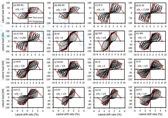
Figure 6.
Comparison between test results and predictions with ACI 318-19.
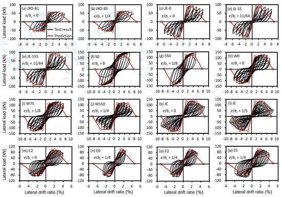
Figure 7.
Comparison between test results and predictions with ACI 352R-02.
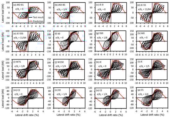
Figure 8.
Comparison between test results and predictions with NZS 3101-2006.
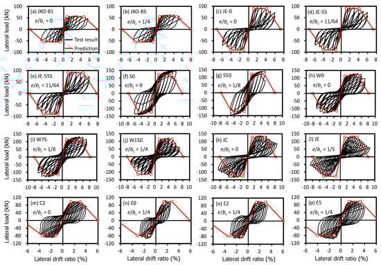
Figure 9.
Comparison between test results and predictions with Eurocode 8.
More specifically, the deformation capacity δu by the predictions were quantitatively compared with the test results δT in Table 4: the deformation capacity δT of the test specimens was defined as the drift ratio corresponding to the nominal strength Py (Equations (5) and (8)) in the post-peak response. As summarized in Table 4, the simplified plastic hinge model using the effective joint width of NZS 3101-2006 [14] or Eurocode 8 [15] matched well with the test results: the mean and COV (coefficient of variation) of δT/δu were 1.07 and 0.113 for the predictions with NZS 3101-2006, respectively, [14] or 0.97 and 0.177 for the predictions with Eurocode 8, respectively [15]. The underestimation of the predictions with ACI 318-19 [12] (1.45 and 0.474) or ACI 352R-02 [13] (1.25 and 0.165) was due to the underestimated effective joint width (Table 3): the effective joint width of the eccentric beam–column joint specimens was symmetrically decreased at both sides due to the beam eccentricity (x) in ACI 318-19 [12] (Equation (1)), and the effect of beam eccentricity was indirectly considered in ACI 352R-02 [13] by using a factor m (Equation (2)). On the other hand, NZS 3101-2006 [14] directly considered the beam eccentricity (e) in the calculation (Equation (3)), and the calculated effective joint width of NZS 3101-2006 [14] was larger than that of ACI 318-19 [12] or ACI 352R-02 [13] but less than that of Eurocode 2 [15] without consideration of the beam eccentricity (Table 3). For these reasons, the simplified plastic hinge model using the effective joint width of NZS 3101-2006 [14] showed the best predictions for all test specimens.
Table 4.
Comparison of deformation capacity between test results and predictions.
It is noted that in eccentric beam–column joints, the joint shear strength could decrease due to additional torsion and stress concentration developed by eccentric beams at the joint interface. Moreover, when a wide column is used, the joint hoop bar stress close to the eccentric beam would be much higher than that far from the eccentric beam [31]. For these reasons, the use of total amount of joint hoop bars could overestimate the performance in the simplified plastic hinge model, particularly for the beam–column joints with a wide column and large beam eccentricity. Of the test specimens, W0, W75, and W150 used wide columns (Table 2 and Table 3). Among them, W150 had the widest column and largest beam eccentricity, and the overestimation in the onset of strength degradation in W150 may be caused by the use of total amount of joint hoop bars (Figure 6j, Figure 7j, Figure 8j and Figure 9j). However, to generalize the effect of joint hoop bars in the case of having a wide column and large beam eccentricity or to suggest an effective joint hoop bar area, existing test results relevant to the case are limited. Thus, further experimental studies are needed.
5. Conclusions
In the present study, the effect of beam eccentricity on the behavior of eccentric beam–column joints was investigated. A simplified plastic hinge model was proposed using the effective joint width of current design codes, and it was applied to existing test specimens. The principal findings can be summarized as follows:
- (1)
- Current design codes provide the effective joint widths for concentric and eccentric beam–column joints, but the effective joint widths vary widely.
- (2)
- In eccentric beam–column joints, the beam eccentricity reduces the effective joint shear area, which results in a decrease in the joint shear strength and more drastic strength degradation after the peak strength.
- (3)
- For nonlinear analysis of eccentric beam–column joints, a simplified plastic hinge model was proposed, addressing the beam eccentricity.
- (4)
- To verify the simplified plastic hinge model, the predictions with various code-specified effective joint widths were compared to the existing test results. The comparison showed that the simplified plastic hinge model with the effective joint width of NZS 3101-2006 matched best to eccentric beam–column joint specimens (for the deformation capacity, the mean and COV of test-to-prediction ratios were 1.07 and 0.113, respectively). Thus, for safer and more economical design of eccentric beam–column joints, the effective joint width of NZS 3101-2006 is recommended to be used in the simplified plastic hinge model.
Compared to concentric beam–column joints, previous experimental studies for eccentric beam–column joints are limited. Considering the fact that eccentric beam–column joints are also common in practice, further studies are needed to investigate the effects of beam eccentricity on the behavior of interior and exterior beam–column joints with various design parameters.
Author Contributions
Conceptualization, H.-J.H.; methodology, H.-J.H. and C.-S.K.; formal analysis, H.-J.H.; resources, H.-J.H. and C.-S.K.; writing—original draft preparation, H.-J.H.; writing—review and editing, C.-S.K.; project administration, H.-J.H.; funding acquisition, H.-J.H. All authors have read and agreed to the published version of the manuscript.
Funding
This paper was supported by Konkuk University in 2020.
Conflicts of Interest
The authors declare no conflict of interest.
References
- Meinheit, D.F.; Jirsa, J.O. Shear Strength of Reinforced Concrete Beam-Column Joints; Report No. 77-1; Department of Civil Engineering, Structures Research Laboratory, University of Texas: Austin, TX, USA, 1977. [Google Scholar]
- Kitayama, K.; Otani, S.; Aoyama, H. Earthquake Resistant Design Criteria for Reinforced Concrete Interior Beam-Column Joints. In Proceedings of the Pacific Conference on Earthquake Engineering, Wairakei, New Zealand, 5–8 August 1987; Volume 1, pp. 315–326. [Google Scholar]
- Leon, R.T. Interior Joints with Variable Anchorage Lengths. J. Struct. Eng. 1989, 115, 2261–2275. [Google Scholar] [CrossRef]
- Bonacci, J.; Pantazopoulou, S. Parametric Investigation of Joint Mechanics. ACI Struct. J. 1993, 90, 61–71. [Google Scholar]
- Hakuto, S.; Park, R.; Tanaka, H. Effect of Deterioration of Bond of Beam Bars Passing through Interior Beam-Column Joints of Flexural Strength and Ductility. ACI Struct. J. 1999, 96, 858–864. [Google Scholar]
- Lee, J.Y.; Kim, J.Y.; Oh, G.J. Strength Deterioration of Reinforced Concrete Beam-Column Joints Subjected to Cyclic Loading. Eng. Struct. 2009, 31, 2070–2085. [Google Scholar] [CrossRef]
- Hong, S.G.; Lee, S.G.; Kang, T.H.K. Deformation-Based Strut-and-Tie Model for Interior Joints of Frames Subject to Load Reversal. ACI Struct. J. 2011, 108, 423–433. [Google Scholar]
- Hwang, H.J.; Eom, T.S.; Park, H.G. Shear Strength Degradation Model for Performance-Based Design of Interior Beam-Column Joints. ACI Struct. J. 2017, 114, 1143–1154. [Google Scholar] [CrossRef]
- Hwang, H.J.; Park, H.G. Requirements of Shear Strength and Hoops for Performance-Based Design of Interior Beam-Column Joints. ACI Struct. J. 2019, 116, 245–256. [Google Scholar] [CrossRef]
- Hwang, H.J.; Park, H.G. Performance-based Shear Design of Exterior Beam-Column Joints with Standard Hooked Bars. ACI Struct. J. 2020, 117, 67–80. [Google Scholar] [CrossRef]
- Feng, F.; Jiang, K.; Hwang, H.J.; Yi, W.J. Earthquake Response of Low-rise RC Moment Frame Structures According to Energy Dissipation Ratio of Beam-Column Joints. J. Struct. Integr. Maint. 2018, 3, 33–43. [Google Scholar] [CrossRef]
- American Concrete Institute (ACI). Building Code Requirements for Structural Concrete and Commentary (ACI 318-19); ACI: Farmington Hills, MI, USA, 2019. [Google Scholar]
- American Concrete Institute (ACI). Recommendations for Design of Beam-Column Connections in Monolithic Reinforced Concrete Structures (ACI 352R-02); ACI: Farmington Hills, MI, USA, 2002. [Google Scholar]
- -Standards New Zealand (NZS). The Design of Concrete Structures (NZS 3101-2006); Springer: Berlin, Germany, 2006; p. 698. [Google Scholar]
- -European Committee for Standardization (CEN). Eurocode 8: Design of Structures for Earthquake Resistance—Part 1: General Rules, Seismic Actions and Rules for Buildings; BS EN 1998-1:2004; CEN: Brussels, Belgium, 2004. [Google Scholar]
- American Society of Civil Engineers (ASCE). Seismic Evaluation and Retrofit of Existing Buildings (ASCE/SEI 41-17); ASCE: Reston, VA, USA, 2017. [Google Scholar]
- Pacific Earthquake Engineering Research Center (PEER). Guidelines for Performance-Based Seismic Design of Tall Buildings; Report No. 2017/06; PEER: Berkely, CA, USA, 2017. [Google Scholar]
- Hwang, S.J.; Lee, H.J. Analytical Model for Predicting Shear Strengths of Exterior Reinforced Concrete Beam-Column Joints for Seismic Resistance. ACI Struct. J. 1999, 96, 846–858. [Google Scholar]
- Hwang, S.J.; Lee, H.J. Analytical Model for Predicting Shear Strengths of Interior Reinforced Concrete Beam-Column Joints for Seismic Resistance. ACI Struct. J. 2000, 97, 35–44. [Google Scholar]
- Park, S.; Mosalam, K.M. Analytical Model for Predicting Shear Strength of Unreinforced Exterior Beam-Column Joints. ACI Struct. J. 2012, 109, 149–159. [Google Scholar]
- Wong, S.H.F.; Kuang, J.S. Predicting Shear Strength of RC Exterior Beam-Column Joints by Modified Rotating-Angle Softened-Truss Model. Comput. Concr. 2011, 8, 59–70. [Google Scholar] [CrossRef]
- LaFave, J.M.; Kim, J. Joint Shear Behavior Prediction for RC Beam-Column Connections. Int. J. Concr. Struct. Mater. 2011, 5, 57–64. [Google Scholar] [CrossRef]
- FEMA 356. Prestandard and Commentary for the Seismic Rehabilitation of Buildings; Federal Emergency Management Agency (FEMA): Washington, DC, USA, 2000.
- Murakami, H.; Fujii, S.; Ishiwata, Y.; Morita, S. Shear Strength and Deformation Capacity of Interior R/C Beam-Column Joint Subassemblage. In Proceedings of the 12th World Conference on Earthquake Engineering, Auckland, New Zealand, 4 February 2000. 0679. [Google Scholar]
- Joh, O.; Goto, Y.; Shibata, T. Behavior of Reinforced Concrete Beam-Column Joints with Eccentricity; Design of Beam-Column Joints for Seismic Resistance, SP-123; Jirsa, J.O., Ed.; American Concrete Institute: Farmington Hills, MI, USA, 1991; pp. 317–357. [Google Scholar]
- Lawrance, G.M.; Beattie, G.J.; Jacks, D.H. The Cyclic Load Performance of an Eccentric Beam-Column Joint. In Central Laboratories Report 91-25126; Central Laboratories: Lower Hutt, New Zealand, 1991; p. 81. [Google Scholar]
- Raffaelle, G.S.; Wight, J.K. Reinforced Concrete Eccentric Beam-Column Connections Subjected to Earthquake-Type Loading. ACI Struct. J. 1995, 92, 45–55. [Google Scholar]
- Teng, S.; Zhou, H. Eccentric Reinforced Concrete Beam-Column Joints Subjected to Cyclic Loading. ACI Struct. J. 2003, 100, 139–148. [Google Scholar]
- Goto, Y.; Joh, O. Shear Resistance of RC Interior Eccentric Beam-Column Joints. In Proceedings of the 13th World Conference on Earthquake Engineering, Vancouver, BC, Canada, 1–6 August 2004; Volume 13, p. 649. [Google Scholar]
- Kusuhara, F.; Azukawa, K.; Shiohara, H.; Otani, S. Tests of Reinforced Concrete Interior Beam-Column Joint Subassemblage with Eccentric Beams. In Proceedings of the 13th World Conference on Earthquake Engineering, Vancouver, BC, Canada, 1–6 August 2004; Volume 14, p. 185. [Google Scholar]
- Lee, H.J.; Ko, J.W. Eccentric Reinforced Concrete Beam-Column Connections Subjected to Cyclic Loading in Principal Directions. ACI Struct. J. 2007, 104, 459–467. [Google Scholar]
- Chen, C.C.; Chen, G.K. Cyclic Behavior of Reinforced Concrete Eccentric Beam-Column Corner Joints Connecting Spread-Ended Beams. ACI Struct. J. 1999, 96, 443–449. [Google Scholar]
- Vollum, R.L.; Newman, J.B. Towards the Design of Reinforced Concrete Eccentric Beam-Column Joints. Mag. Concr. Res. 1999, 51, 397–407. [Google Scholar] [CrossRef]
- Ma, C.; Wang, Z.; Smith, S.T. Seismic Performance of Large-Scale RC Eccentric Corner Beam-Column-Slab Joints Strengthened with CFRP Systems. J. Compos. Constr. 2020, 24, 04019066. [Google Scholar] [CrossRef]
- Burak, B.; Wight, J.K. Seismic Behavior of Eccentric R/C Beam-Column-Slab Connections under Sequential Loading in Two Principal Directions. In ACI Fifth International Conference on Innovations in Design with Emphasis on Seismic, Wind and Environmental Loading, Quality Control, and Innovation in Materials/Hot Weather Concreting; SP-209; Malhotra, V.M., Ed.; American Concrete Institute: Farmington Hills, MI, USA, 2002; pp. 863–880. [Google Scholar]
- Shin, M.; LaFave, J.M. Seismic Performance of Reinforced Concrete Eccentric Beam-Column Connections with Floor Slabs. ACI Struct. J. 2004, 101, 403–412. [Google Scholar]
- Hwang, H.J.; Park, H.G. Plastic Hinge Model for Performance-Based Design of Beam-Column Joints. J. Struct. Eng. 2021, 147, 04020336. [Google Scholar] [CrossRef]
- Eom, T.S.; Hwang, H.J.; Park, H.G. Energy-Based Hysteresis Model for Reinforced Concrete Beam-Column Connections. ACI Struct. J. 2015, 112, 157–166. [Google Scholar]
Publisher’s Note: MDPI stays neutral with regard to jurisdictional claims in published maps and institutional affiliations. |
© 2021 by the authors. Licensee MDPI, Basel, Switzerland. This article is an open access article distributed under the terms and conditions of the Creative Commons Attribution (CC BY) license (http://creativecommons.org/licenses/by/4.0/).