Article

Coupled Thermomechanical Responses of Zirconium Alloy System Claddings under Neutron Irradiation

1
National Engineering Research Center for Equipment and Technology of Cold Rolled Strip, School of Mechanical Engineering, Yanshan University, Qinhuangdao 066004, China
2
State Key Laboratory of Nuclear Fuel and Materials, The First Sub-Institute, Nuclear Power Institute of China, Chengdu 610041, China
*
Author to whom correspondence should be addressed.
H.Z. and C.Y. contributed equally to this work.
Appl. Sci. 2021, 11(3), 1308; https://doi.org/10.3390/app11031308
Submission received: 23 December 2020 / Revised: 23 January 2021 / Accepted: 26 January 2021 / Published: 1 February 2021

Abstract

:
Zirconium (Zr) alloy is a promising fuel cladding material used widely in nuclear reactors. Usually, it is in service for a long time under the effects of neutron radiation with high temperature and high pressure, which results in thermomechanical coupling behavior during the service process. Focusing on the UO2/Zr fuel elements, the macroscopic thermomechanical coupling responses of pure Zr, Zr-Sn, and Zr-Nb binary system alloys, as well as Zr-Sn-Nb ternary system alloy as cladding materials, were studied under neutron irradiation. As a heat source, the thermal conductivity and thermal expansion coefficient models of the UO2 core were established, and an irradiation growth model of a pure Zr and Zr alloy multisystem was built. Based on the user material subroutine (UMAT) with ABAQUS, the current theoretical model was implemented into the finite element framework, and the consequent thermomechanical coupling behavior under irradiation was calculated. The distribution of temperature, the stress field of the fuel cladding, and their evolution over time were analyzed. It was found that the stress and displacement of the cladding were sensitive to alloying elements due to irradiated growth.

1. Introduction

With sources of fossil fuels becoming increasingly exhausted and the environmental challenges associated with their use, efficient and clean nuclear energy will become a promising energy source in the future. The most significant issue with nuclear power is its safety and controllability in the long term. Cladding is one of the most important components in a nuclear reactor. It has been used in extreme environments with high radiation levels, high temperatures, and high pressure levels for a long time [1]. Zirconium (Zr) alloys have been applied as a cladding material because of their high temperature mechanical properties, small neutron absorption cross section, strong radiation resistance, and good irradiation stability [2]. The properties of the Zr alloy clad and UO2 fuel are critical issues to be resolved for nuclear power [3,4]. However, the effects that extreme environments—e.g., with high irradiation levels, high temperatures, and high pressure levels—have on the mechanical and thermal properties of Zr alloy cannot be determined through conventional experimental methods [5,6]. Experimental data on optimizing component structure properties is lacking.
Numerical simulations provide an effective method for performance analyses of nuclear materials in extreme environments. Bison, a three-dimensional finite element analysis program developed by the National Laboratory of Idaho, USA, has been used to simulate the thermal mechanical behavior of fuel rods in the reactor [7]. Alcyone, a three-dimensional finite element analysis program developed by the CEA of France, has been used to study the high burnup performance of fuel [8]. The user subroutine UMAT of ABAQUS finite element software was employed to study the radiation-thermal-mechanical coupling behavior of fuel rods by Tang et al. [9]. The effects of a nonhomogeneous irradiation environment were studied using the UMAT of ABAQUS. The three-dimensional deformation of a typical 17 × 17 fuel assembly was determined by numerical simulation [10]. The thermomechanical behavior simulation, coupled with the hydrostatic-pressure-dependent, grain-scale fission gas swelling calculation for a monolithic UMo fuel plate, was studied under heterogeneous neutron irradiation [11]. The thermomechanical behavior of a Zr-4 fuel rod was studied by experiments and a simulation. It was found that the creep behavior was not captured by a simple law [12]. The deformation behavior of Zr alloys was also investigated at the microscale level. A physically-based crystal plasticity model was proposed to study the contact force and gap opening of fuel rod assembly by Patra and Tome [13]. The effects of fast neutron irradiation on the tensile deformation mechanism of Zr-2.5 pressure tube samples was studied by in situ neutron diffraction [14]. It was found that the starting stress of base plane <a> slip and cylinder <a> slip increased due to neutron diffraction, while the influence of cone < c + a > slip was small and became the dominant deformation mechanism. After the model was established, the SRIM/TRIM software could be used to conduct an ion energy analysis on the thickness of the model to evaluate its safety and stability, and provide a scientific basis for the subsequent behavior model in the fuel rod reactor [15].
Irradiation-induced hardening was confirmed for the Zr alloy cladding. An increase of Nb was shown to be able to retard the formation of irradiation defects [16]. The thermomechanical behavior of Zr alloys with UO2/Zr fuel element is key for nuclear reactors. At the same time, the alloying elements in the Zr alloy for the nuclear reactor can also affect the properties of Zr alloys. For example, tin can improve the strength of Zr, reduce its plasticity, and improve its creep and corrosion. Niobium has a high strengthening effect on Zr; the thermal neutron absorption cross-section of niobium is very small, which can eliminate the detrimental effects of impurities such as C, Ti, and Al on the corrosion resistance of Zr, and reduce the hydrogen absorption capacity of Zr. Copper has also a significant strengthening effect on Zr. A small amount of copper can reduce the impact toughness of Zr, and improve the corrosion resistance of Zr-Nb alloy at high temperature [17]. The refractory metal Zr may therefore be a promising cladding material with excellent high-temperature properties [18,19]. The effect of alloy elements on the irradiation behavior of cladding is important in the development of cladding materials. Therefore, pure Zr, Zr-Sn, and Zr-Nb binary systems, and the Zr-Sn-Nb ternary system were considered as cladding materials in this study of the thermomechanical behavior of the UO2/Zr fuel element. The effect of neutron irradiation on the mechanical and thermal properties of Zr and Zr alloy, as well as the temperature field, displacement field, and stress field of Zr alloy cladding under neutron irradiation, were studied using the ABAQUS distribution and evolution mechanism.

2. Thermomechanical Modelling Framework

2.1. Thermomechanical Model of UO2 Fuel

The thermal properties of UO2 depend on the temperature, porosity, and burnup. In the present study, UO2 fuel was the only considered heat source. The thermal conductivity of fuel UO2 was calculated using the Fink-Lucuta model, which is valid from 298 to 3120 K [20,21]:
k U O 2 = k 95 F D F P F M F x F R
where k95 is the thermal conductivity of unirradiated UO2 at 95% theoretical density in W/(m·K). In the present study, the temperature dependence of annealing on irradiation defects was considered in the thermal conductivity of UO2.
k 95 = 1 0.041 + 2.165 × 10 4 T + ( 1 + 396 e 6380 / T ) 1 + [ 4.715 × 10 9 T 2 ] exp ( 16361 T )
where T is temperature in K, and FD and FP are the impact factors of dissolved and precipitated fission products on thermal conductivity, respectively.
F D = [ 1.09 B 2.265 + 0.0643 B T ] × arctan ( 1.09 B 2.265 + 0.0643 B T ) 1
F P = 1 + ( 0.019 B 3 0.019 B ) [ 1 + exp ( 1200 T 100 ) ] 1
where Fx is the deviation from stoichiometry (1.0 for urania fuel), FR and FM are the impact factor of irradiated effect and the porosity, respectively, and B is fuel consumption in atom%, B = 50%.
F R = 1 0.019 B 1 + exp ( T 900 80 )
F M = 1 P 1 + ( s 1 ) P
where P is the porosity and s is the shape factor that is spherical in this work, s = 0.5.
The coefficient of thermal expansion was calculated using Equation (7):
Δ L L = K 1 T K 2 + K 3 exp ( E D K T )
where ED and KT are the thermodynamic parameters and Boltzmann constant, ED = 6.9 × 10 − 20 J and KT = 1.38 × 10⁻²³ J/K respectively. The values of Ki are K1 = 1.0 × 10⁻⁵ K−1, K2 = 3.0 × 10⁻³ K−1 and K3 = 4.0 × 10⁻² K−1 respectively. The density and Poisson’s ratio are 10.96 g/cm3 and 0.316, respectively.

2.2. Thermomechanical Models of Zr Cladding

In the current work, pure Zr, Zr-4 alloy, Zr-2.5Nb-0.5Cu alloy, and N36 alloy were studied. The thermal conductivity of Zr alloy from room temperature to melting point was shown to be temperature dependent [22]:
k = 8.8527 + 7.0820 × 10 3 T 2.5329 × 10 6 T 2 + 2.29918 × 10 3 T 1
Irradiation growth and creep of cladding are important mechanical behaviors under neutron irradiation [23]. The irradiation growth of Zr and its alloys were calculated according to a power-law empirical model [24,25]. The axial strain is described as
ε z = A ( Φ t ) n
The strain increment of the irradiation growth is given as
Δ ε z = A ( Φ t ) n A ( Φ ( t Δ t ) n )
where εz is the axial strain, induced by irradiation growth, Φ is the fast neutron fluence rate, and A and n are the material parameters. The model parameters of irradiation growth for different Zr alloys are shown in Table 1. A = 1.2 × 10⁻²¹ N/cm2, n = 0.794.
Due to the volume conserving of the irradiation growth of the cladding [26], the growth in the other two directions was assumed to be consistent; the radial strain εr is given by
ε r = ( 1 1 1 + ε z )

3. Finite Element Modeling

The fuel rod contained 40 pellets with a radius of 4.09 mm. The inner diameter and thickness of the cladding were 4.16 mm and 0.57 mm, respectively. The length of the simulated tube was 200 mm, as shown in Figure 1a. The initial gap distance was set at 0.07 mm, as shown in Figure 1b. The reduced integration FEs (C3D8R) were employed in ABAQUS, and the number of meshes was 10,100. Due to the axial symmetry of cladding cube, axisymmetric boundary conditions were applied, and the node along the mid-circumference was constrained at the axial end of the cladding to prevent rigid body rotation.
The cladding material parameters of fuel rods are shown in Table 1, Table 2, Table 3 and Table 4.
In the simulation process, the left and right end faces of the cladding were fixed, and the heat source was the core area of the pellet. The pellet core was heated to 1200 °C by radial irradiation. The cooling coefficient of the outer surface of the fuel rod was set at 20,000 W/(m2·K), which made the outer surface of the fuel rod gradually cool down. The coolant pressure was kept at a constant value of 15.5 MPa during the entire simulation process. The initial pressure of helium precharged in the pellet cladding gap was 2 MPa. The simulated power was calculated according to the average power of the nuclear power plant, which was 200 W/cm. A power increase of 1 d resulted in a rise from 0 W/cm to 200 W/cm, and the steady state operation of 200 W/cm took 1200 days. During steady state operation, the fast neutron fluence rate of the fuel rod remained constant, and its value was 9.5 × 10¹⁷ n/(mm2·s). In the simulation, the input parameters were obtained from the practical working conditions of the reactor pressure vessel.

4. Results and Discussion

4.1. The Thermomechanical Behavior

The temperature field distribution in ℃ of the fuel elements after irradiation for 1200 days is shown in Figure 2, which are pure Zr, N36, Zr-4, and Zr-2.5Nb-0.5Cu. The temperature distribution in the radial direction at the middle part of the cladding and the axial direction at the ends of the cladding are presented, respectively. It was observed from the simulation results that the temperature of the inner surface was the highest under irradiation, and that this decreased gradually from the inner to outer surface along the radial direction due to the action of the coolant. The distribution of temperature showed a gradient increasing trend at the end of the cladding in the axial direction. In the simulation, the temperature of the four cladding materials was maintained at 300 to 320 °C under the action of the coolant, which was consistent with the value and distribution of the cladding temperature of the LWR fuel rod [27]. The distribution of temperature was the same for pure Zr and Zr alloy. The results show that the composition of alloying elements has little effect on the temperature distribution and magnitude of the cladding tube under neutron irradiation.
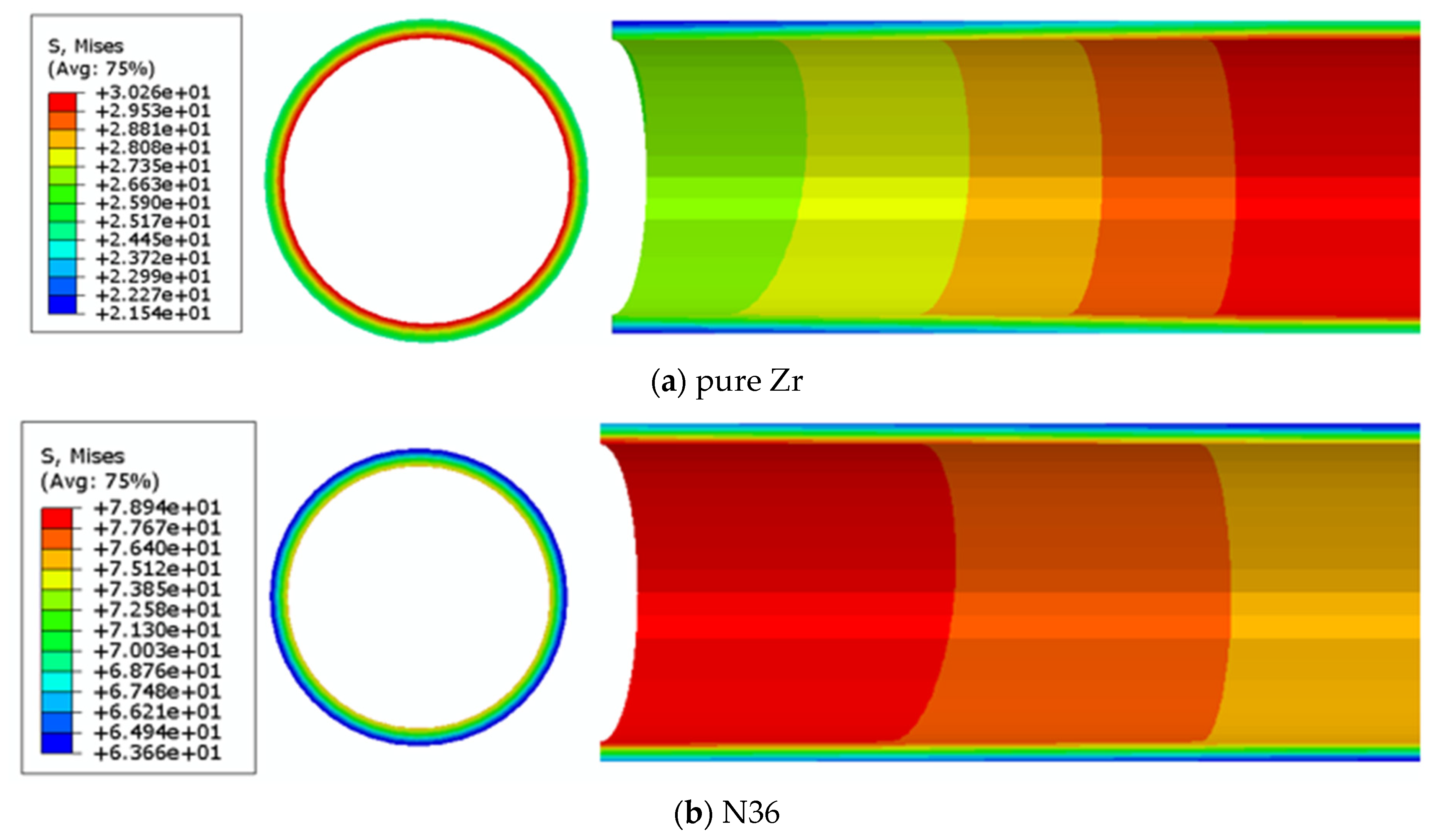
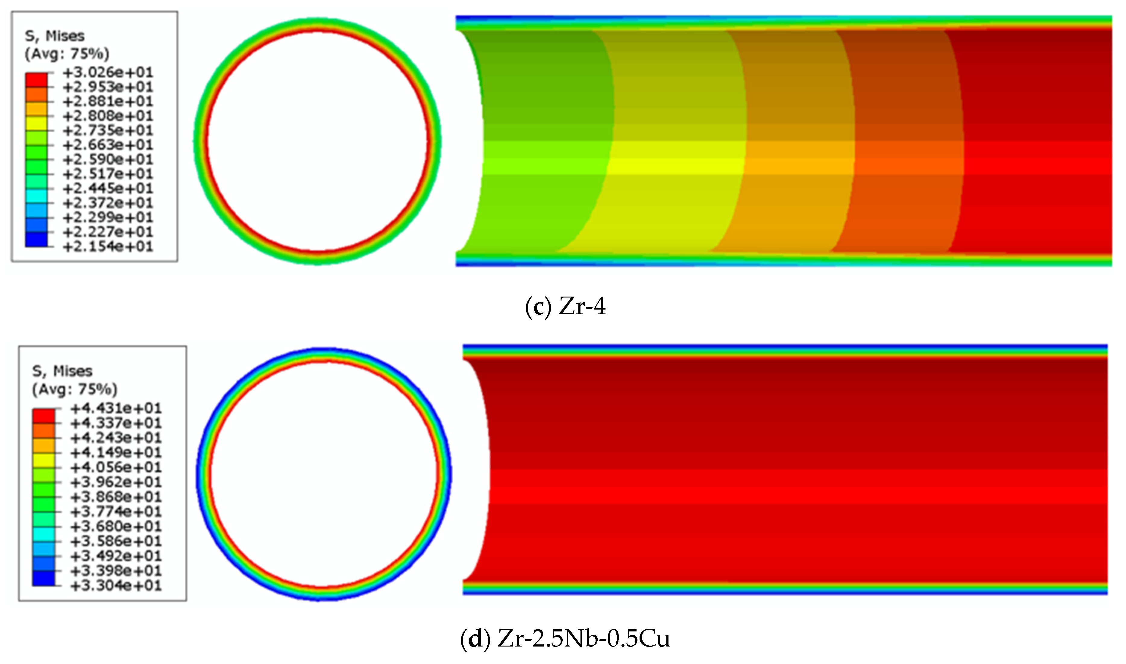
In the present study, the thermomechanical behavior of the cladding was studied under normal operating conditions. In the initial stage, the pressure on the cladding was due to the compressive stress from the outer surface to the inner surface, induced by the coolant pressure (15.5 MPa) and the helium pressure (2 MPa) in the gap. Figure 3 shows the Mises stress field distributions in the MPa of cladding for different alloy systems during stable operation for 1200 days under irradiation conditions; these data can be employed to evaluate the cladding safety. It may be observed from the simulation results that the stress field distribution of the cladding was similar to the temperature field distribution; namely, the stress gradually decreased from the inner to the outer surface of the cladding in the radial direction. The distribution of stress along the radial direction was the same for the four alloys, which is consistent with the SiC/SiC composite cladding at the end of its life [28]. The stress was related to the temperature of the cladding produced by fuel burnup. Therefore, the gradient distribution of stress along the radial direction was shown to be independent of the alloys of cladding materials.
However, the axial stress distribution of the cladding was found to be dependent on the alloy element. In the pure Zr and Zr-4 alloy, the stress level was low at the end. The stress gradually increased from the end to center, along the axial direction, as shown in Figure 3a,c. The maximum magnitudes of both pure Zr and Zr-4 alloys were about 30.2 MPa on the 1200th day. In contrast, the stress was high at the end for the N36 alloy. The stress distribution of the N36 alloy showed that the stress decreased from the end to the center along the axial direction, as shown in Figure 3b. Uniform stress distribution was observed along the axial direction for the Zr-2.5Nb-0.5Cu alloy, as shown in Figure 3d. The maximum magnitudes of the N36 and Zr-2.5Nb-0.5Cu alloys were about 78.9 MPa and 44.3 MPa on the 1200th day, respectively. This axial stress distribution led to different axial strains for different cladding materials. Therefore, axial deformation should be considered as an important parameter for selecting a cladding material.

4.2. The Change of Gap Distance

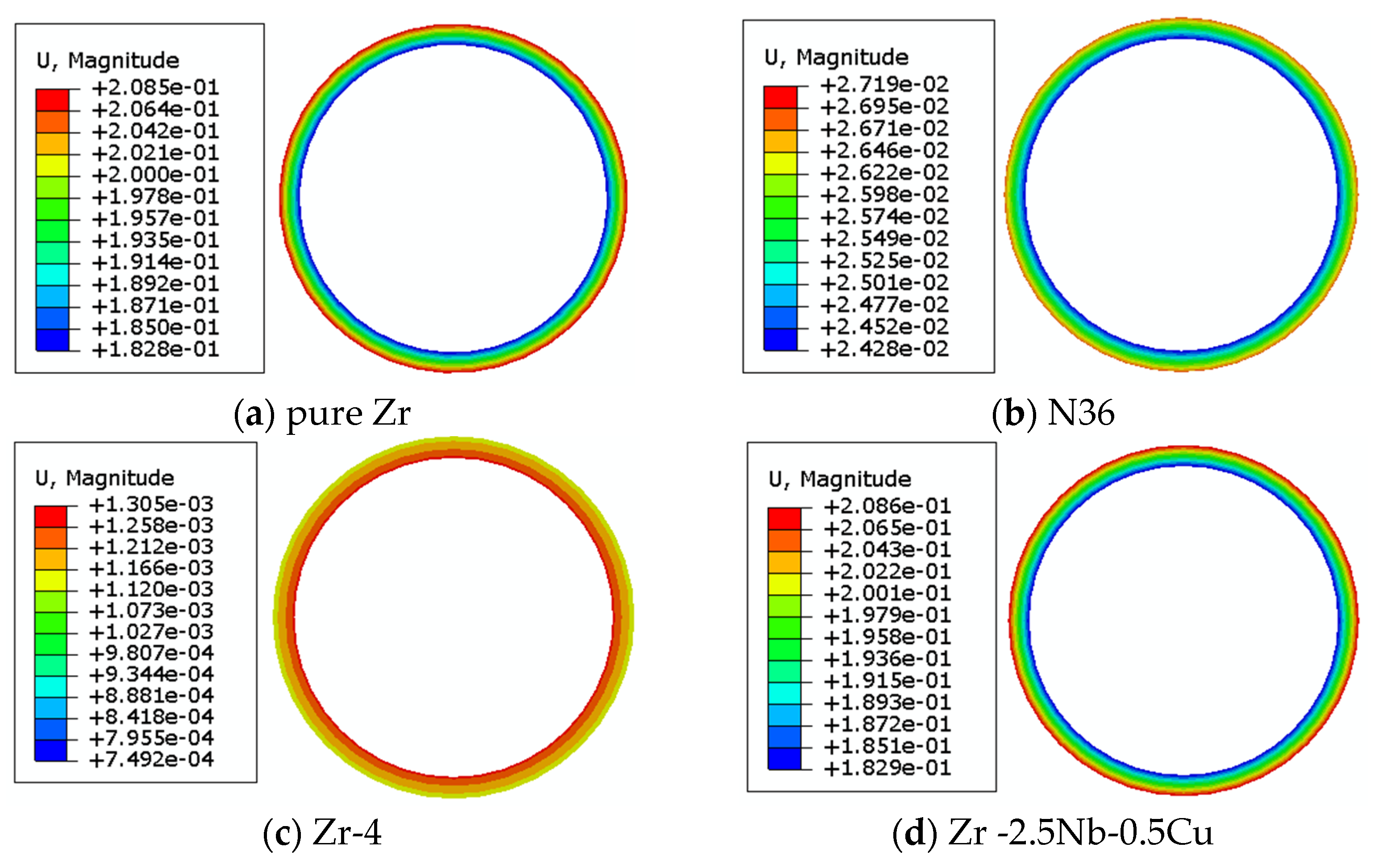
The displacement fields, in mm distribution of cladding, of different alloy systems irradiated under stable operation for 1200 days, are shown in Figure 4. The results show that the displacement field of the four cladding materials presented a gradient distribution along the radial direction. It was found that the outer surface of the cladding had a large displacement deformation due to the irradiation of pure Zr, N36, and Zr -2.5Nb-0.5Cu alloys. In contrast, a large displacement deformation was observed on the inner surface for the Zr-4 alloy, as shown in Figure 4c. The change of the displacement deformation was affected by the alloy system due to thermal expansion and irradiation-induced growth. Normally, there is no contact between the inner surface of the cladding and the outer surface of the fuel pellet for safety reasons; however, this may occur due to displacement deformation along radial direction.
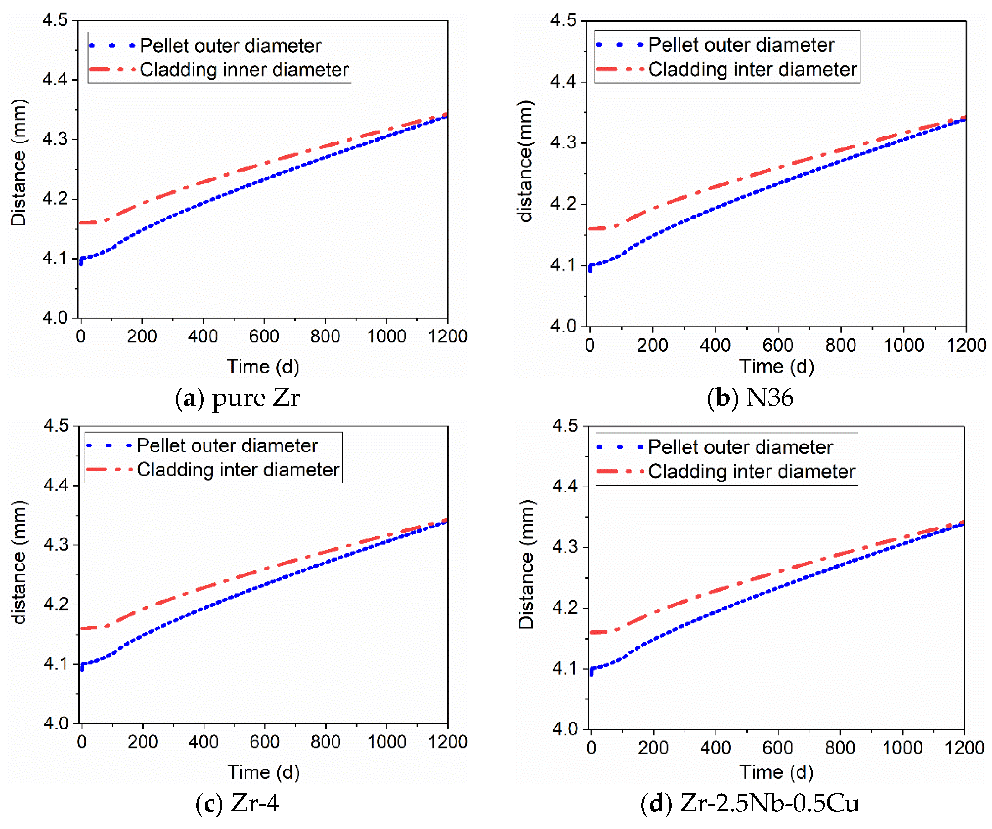
There is typically a gap between pellet and cladding (i.e., the difference between the radial distance on the inner surface of the cladding and the radial distance on the outer surface of the pellet). In order to study the change of gap distance between the pellet and the cladding, the radial distance between the outer surface of the pellet and the inner surface of the cladding is also an important index. The radial distances of cladding and pellet are presented in Figure 5. It was shown that the radial distance increased with running time. At the beginning of the simulation, the radial distance of the fuel increased rapidly, which was ascribed to the heating and expansion of the fuel. The gap distance gradually decreased due to irradiation growth from the simulation results. The initiation of Pellet Cladding Mechanical Interaction (PCMI) can take place at the end due to burnups of pellets, which will induce additional cladding growth from pellet expansion [29]. The change rule of the gap is consistent with the reactor behavior of PWR SiC cladding fuel rods [30]. This is mainly due to the rapid increase of the local thickness of the pellet under irradiation. As the irradiation time increases, the gas distance decreases, which leads to a short service period of the four cladding materials. The performance of irradiation growth resistance for Zr-based alloy cladding could be improved by using a multi-alloy system.

5. Conclusions

In this study, radiation growth models of Zr alloys of different types, i.e., pure Zr, Zr-Sn, a Zr-Nb binary system, and a Zr-Sn-NB ternary system, were established for UO2/Zr fuel elements. The thermal mechanical coupling behavior of different system alloys under irradiation was simulated and calculated. The distribution and evolution laws of temperature field, displacement field, and stress field were analyzed:
  • The temperature field and stress field of the fuel element decreased gradually from the center to the surface along the radial direction, and the maximum value appeared in the core of the pellet.
  • The results show that the distribution of the displacement field along the radial direction increased gradually from the center to the outer surface. The increase of the displacement of the outer surface of the pellet was due to the increase of the local thickness, which was due to the irradiation effect.
  • Different alloy systems did not affect the distribution of the temperature field, displacement field, or stress field of the UO2/Zr fuel element under irradiation. The values of temperature, displacement, and stress change with the change of alloy system. The displacement and stress fields were more sensitive to the alloy system; that is, the macroscopic mechanical properties of the fuel element under irradiation were shown to be sensitive to alloy elements.

Author Contributions

Conceptualization, L.W. and B.S.; data curation, H.Z. and C.Y.; formal analysis, D.G. and R.P.; funding acquisition, L.W. and B.S.; investigation, H.Z. and C.Y.; methodology, J.M., J.Q. and H.Z.; project administration, B.S.; software, H.Z.; supervision, B.S. and L.W.; validation, H.Z. and C.Y.; visualization, R.P., J.Q. and J.M.; writing—original draft, C.Y. and H.Z.; writing—review & editing, C.Y., H.Z. and B.S. All authors have read and agreed to the published version of the manuscript.

Funding

Financial support from the NSFC [51771166], the Foundation for Distinguished Young Scholars of Hebei Province [E2019203452] and the State Key Laboratory of Materials Processing and Die & Mould Technology, Huazhong University of Science and Technology [P2020-013] are gratefully acknowledged.

Data Availability Statement

The raw data required to reproduce these findings are available to download from [https://zenodo.org/record/4482035#.YBV9YUBI-po].

Conflicts of Interest

The authors declare no conflict of interest.

References

  1. Hallstadius, L.; Johnson, S.; Lahoda, E. Cladding for high performance fuel. Prog. Nucl. Energ. 2012, 57, 71–76. [Google Scholar] [CrossRef]
  2. Was, G.S.; Petti, D.; Ukai, S.; Zinkle, S. Materials for future nuclear energy systems. J. Nucl. Mater. 2019, 527, 151837. [Google Scholar] [CrossRef]
  3. Zinkle, S.J.; Was, G.S. Materials challenges in nuclear energy. Acta Mater. 2013, 61, 735–758. [Google Scholar] [CrossRef]
  4. Hosemann, P.; Frazer, D.; Fratoni, M.; Bolind, A.; Ashby, M.F. Materials selection for nuclear applications: Challenges and opportunities. Scripta Mater. 2018, 143, 181–187. [Google Scholar] [CrossRef] [Green Version]
  5. Lambrecht, M.; Malerba, L. Positron annihilation spectroscopy on binary Fe-Cr alloys and ferritic/martensitic steels after neutron irradiation. Acta Mater. 2011, 59, 6547–6555. [Google Scholar] [CrossRef]
  6. Reese, E.R.; Almirall, N.; Yamamoto, T.; Tumey, S.; Odette, G.R.; Marquis, E.A. Does rate dependence of Cr precipitation in an ion-irradiated Fe-18Cr alloy. Scripta Mater. 2018, 146, 213–217. [Google Scholar] [CrossRef]
  7. Williamson, R.L.; Novascone, S.R. Application of the BISON Fuel Performance Code to the FUMEX-III Coordinated Research Project; International Atomic Energy Agency (IAEA): Vienna, Austria, 2012. [Google Scholar]
  8. Thouvenin, G.; Ricaud, J.M.; Michel, B. Alcyone: The PLEIADES fuel performance code dedicated to multidimensional PWR studies. In Proceedings of the International Meeting on LWR Fuel Performance, Salamanca, Spain, 22–26 October 2006. [Google Scholar]
  9. Tang, C.B.; Jiao, Y.J.; Chen, P.; Li, H.M.; Zhou, Y. Numerical Simulation of Irradiation-Thermal-Mechanical Coupling Behaviors in Nuclear Fuel Rods. Nucl. Power Eng. 2017, 38, 180–184. (In Chinese) [Google Scholar]
  10. Li, M.; Li, H.M.; Chen, P.; Wang, H.Y.; Pu, Z.P.; Qi, M.; Zhu, F.W. Preliminary Numerical Simulation of Fuel Assembly Deformation under Non-Homogeneous Irradiation Environment. Nucl. Power Eng. 2017, 38, 7–10. [Google Scholar]
  11. Kong, X.; Tian, X.; Yan, F.; Ding, S.; Hu, S.; Burkes, D.E. Thermo-mechanical behavior simulation coupled with the hydrostatic-pressure-dependent grain-scale fission gas swelling calculation for a monolithic UMo fuel plate under heterogeneous neutron irradiation. Open Eng. 2018, 8, 243–260. [Google Scholar] [CrossRef]
  12. Yadav, A.K.; Shin, C.H.; Lee, S.U.; Kim, H.C. Experimental and numerical investigation on thermo-mechanical behavior of fuel rod under simulated LOCA conditions. Nucl. Eng. Des. 2018, 337, 51–65. [Google Scholar] [CrossRef]
  13. Patra, A.; Tome, C.N. Finite element simulation of gap opening between cladding tube and spacer grid in a fuel rod assembly using crystallographic models of irradiation growth and creep. J. Nucl. Mater. 2017, 315, 155–169. [Google Scholar] [CrossRef] [Green Version]
  14. Long, F.; Balogh, L.; Brown, D.W.; Mosbrucker, P.; Skippon, T.; Judge, C.D.; Daymond, M.R. Effect of neutron irradiation on deformation mechanisms operating during tensile testing of Zr-2.5Nb. Acta Mater. 2016, 102, 352–363. [Google Scholar] [CrossRef] [Green Version]
  15. Sarswat, P.K.; Jagannathan, M. Deflection behavior of focused-ion-beam deposited carbon nanocantilever and overhung structures. Adv. Mater. Lett. 2017, 8, 324–330. [Google Scholar] [CrossRef]
  16. Li, Y.; Ghoniem, N. Cluster dynamics modeling of irradiation growth in single crystal Zr. J. Nucl. Mater. 2020, 540, 152312. [Google Scholar] [CrossRef]
  17. Liu, J. Nuclear Structural Materials; Chemical Industry Press: Shanghai, China, 2007; pp. 30–35. [Google Scholar]
  18. Kareer, A.; Waite, J.C.; Li, B.; Couet, A.; Armstrong, D.E.J.; Wilkinson, A.J. Short communication: ‘Low activation, refractory, high entropy alloys for nuclear applications’. J. Nucl. Mater. 2019, 526, 151744. [Google Scholar] [CrossRef]
  19. Sarswat, P.K.; Sarkar, S.; Murali, A.; Huang, W.; Tan, W.; Free, M.L. Additive manufactured new hybrid high entropy alloys derived from the AlCoFeNiSmTiVZr system. Appl. Surf. Sci. 2019, 476, 242–258. [Google Scholar] [CrossRef]
  20. Lucuta, P.G.; Matzke, H.; Hastings, I.J. A pragmatic approach to modelling thermal conductivity of irradiated UO2 fuel: Review and recommendations. J. Nucl. Mater. 1996, 232, 166–180. [Google Scholar] [CrossRef]
  21. Carbajo, J.; Gradyon, L.; Popov, S.; Ivanov, V. A review of the thermophysical properties of MOx and UO2 fuels. J. Nucl. Mater. 2001, 299, 181–198. [Google Scholar] [CrossRef]
  22. Fink, J.K.; Leibowitz, L. Thermal conductivity of zirconium. J. Nucl. Mater. 1995, 226, 44–50. [Google Scholar] [CrossRef]
  23. Adamson, R.B.; Coleman, C.E.; Griffiths, M. Irradiation creep and growth of zirconium alloys: A critical review. J. Nucl. Mater. 2019, 521, 167–244. [Google Scholar] [CrossRef]
  24. Hagrman, D.L.; Reymann, G.A. Matpro-Version 11: A Handbook of Materials Properties for Use in the Analysis of Light Water Reactor Fuel Rod Behavior; Technical Report; Idaho National Engineering Lab.: Idaho Falls, ID, USA, 1979.
  25. Rashid, Y.; Dunham, R.; Montgomery, R. Fuel Analysis and Licensing Code: Falcon Mod01; Technical Report EPRI 1011308; Electric Power Research Institute: Washington, DC, USA, 2004. [Google Scholar]
  26. Holt, R.A.; Causey, A.R. Volume conservation during irradiation growth of Zr-2.5Nb. J. Nucl. Mater. 2004, 335, 529–533. [Google Scholar] [CrossRef]
  27. Williamson, R.L. Enhancing the ABAQUS thermomechanics code to simulate multipellet steady and transient LWR fuel rod behavior. J. Nucl. Mater. 2011, 415, 74–83. [Google Scholar] [CrossRef]
  28. Singh, G.; Terrani, K.; Katoh, Y. Thermo-mechanical assessment of full SiC/SiC composite cladding for LWR applications with sensitivity analysis. J. Nucl. Mater. 2018, 499, 126–143. [Google Scholar] [CrossRef]
  29. Cazado, M.E.; Goldberg, E.; Togneri, M.A.; Denis, A.; Soba, A. A new irradiation growth model for Zr-based components of nuclear reactors for the DIONISIO code. Nucl. Eng. Des. 2021, 373, 111009. [Google Scholar] [CrossRef]
  30. Li, W.; Shirvan, K. ABAQUS analysis of the SiC cladding fuel rod behavior under PWR normal operation conditions. J. Nucl. Mater. 2019, 555, 14–27. [Google Scholar] [CrossRef]
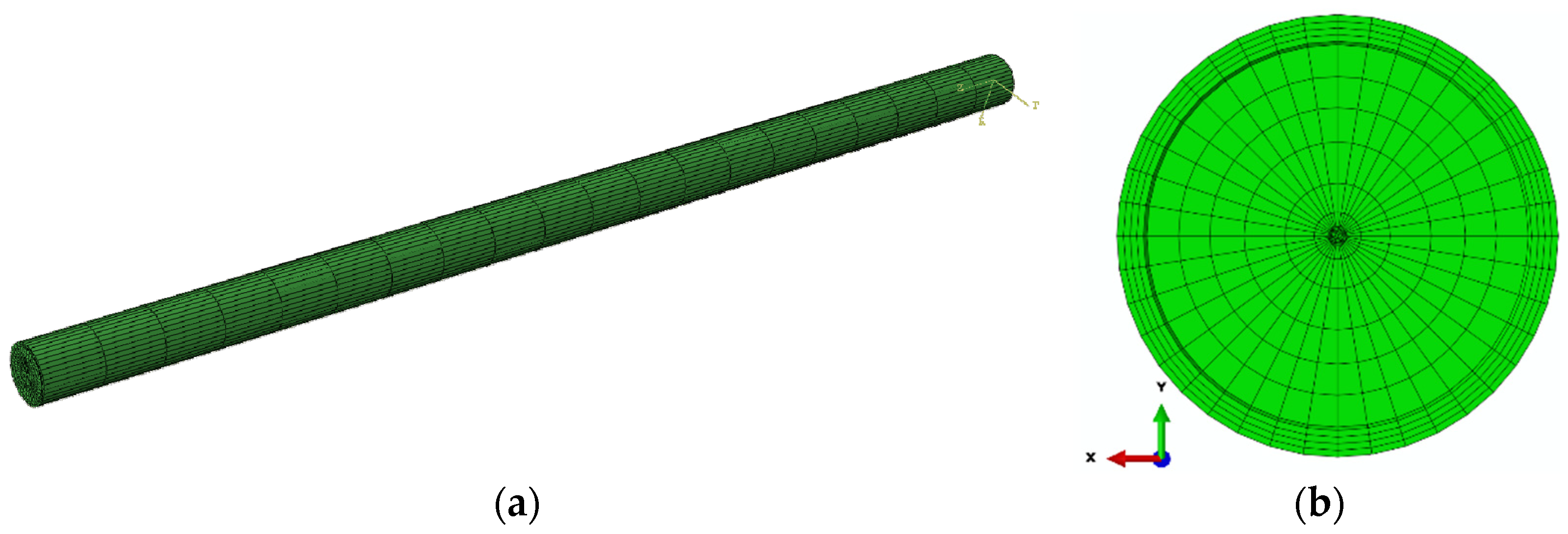
Figure 1. Fuel rod finite element model, (a) global geometry, and (b) the cross-section element.
Applsci 11 01308 g001
Figure 2. Temperature field of different Zr alloy systems irradiated for 1200 days (unit: ℃).
Applsci 11 01308 g002
Figure 3. Stress field of different Zr alloy systems irradiated for 1200 days (unit: MPa).
Applsci 11 01308 g003aApplsci 11 01308 g003b
Figure 4. Displacement field of different zirconium alloy systems irradiated for 1200 days (unit: mm).
Applsci 11 01308 g004
Figure 5. The gap distance–time curves of different alloys.
Applsci 11 01308 g005
Table 1. Pure Zr parameters of fuel rod cladding.
Density
g/cm3
Temperature
°C
Neutron Injection Quantity n/mm2Young’s Modulus
GPa
Thermal Conductivity
W/ (m·°C)
Poisson’s RatioSpecific Heat Capacity
J/(kg·°C)
6.59 10022494.418.40.33272
-20089989.219.1-285
-300337682.419.6-301
-4001,746,00073.820.7-318
Table 2. Zr-4 alloy parameters of fuel rod cladding.
Density
g/cm3
Temperature
°C
Neutron Injection Quantity n/mm2Young’s Modulus
GPa
Thermal Conductivity
W/ (m·°C)
Poisson’s RatioSpecific Heat Capacity
J/(kg·°C)
6.59 100224887.460.3283
-2008998311.17-314
-30033767712.68-333
-4001,746,0007214.03-345
Table 3. Zr-2.5Nb-0.5Cu alloy parameters of fuel rod cladding.
Density
g/cm3
Temperature
°C
Neutron Injection Quantity n/mm2Young’s Modulus
GPa
Thermal Conductivity
W/ (m·°C)
Poisson’s RatioSpecific Heat Capacity
J/(kg·°C)
6.573 10022495.37.590.3275
-20089988.611.26-309
-30033768312.75-326
-4001,746,00077.214.52-335
Table 4. N36 alloy parameters of fuel rod cladding.
Density
g/cm3
Temperature
°C
Neutron Injection Quantity n/mm2Young’s Modulus
GPa
Thermal Conductivity
W/ (m·°C)
Poisson’s RatioSpecific Heat Capacity
J/(kg·°C)
6.49 100224957.460.3283
-2008998911.17-314
-30033768312.68-333
-4001,746,0007714.03-345
Publisher’s Note: MDPI stays neutral with regard to jurisdictional claims in published maps and institutional affiliations.