Abstract
In order to eliminate the calculation error of the Hertzian elastohydrodynamic contact stress due to the asymmetry of the contact region of the helix raceway, a non-Hertzian elastohydrodynamic contact stress calculation method based on the minimum excess principle was proposed. Firstly, the normal contact stresses of the screw raceway and the nut raceway were calculated by the Hertzian contact theory and the minimum excess principle, respectively. Subsequently, the Hertzian solution and the non-Hertzian solution of the elastohydrodynamic contact stress could be determined by the Reynolds equation under different helix angles and screw speeds. Finally, the friction torque test of the double-nut ball screws was designed and implemented on a self-designed bed for validation of the proposed method. The comparison showed that the experimental friction torque was the good agreement with the simulated friction torque, which verified the effectiveness and correctness of the non-Hertzian elastohydrodynamic contact stress calculation method. Under the large helix angle, the calculation accuracy of asperity contact stress for the non-Hertzian solution was more accurate than that of the Hertzian solution at the contact region of ball screws. Therefore, the non-Hertzian elastohydrodynamic contact stress considering the asymmetry of the raceway contact region could more accurately analyze the wear depth of the high-speed ball screws.
1. Introduction
With the improvement of machining efficiency and machining accuracy of the NC machine tools, high-speed ball screws (BSs) are widely used in the machining field [1,2]. However, there is a calculation error problem of the Hertzian elastohydrodynamic contact stress due to the asymmetry of the contact region of the helix raceway. Thus, it is essential to investigate the non-Hertzian elastohydrodynamic contact stress of the BSs in these properties, such as kinematics, force balance, and elastohydrodynamic contact mechanics.
In terms of the force and deformation characteristics of the double-nut ball screws (DNBSs), many researchers studied the force balance equation and the torque balance equation of the working ball. Liu et al. [3] proposed a static load distribution model of the preloaded BSs considering geometric errors, which takes into account the influence of non-loaded balls and the interaction between the elastic deformation of a screw/nut and the Hertz contact forces of screw–ball/nut–ball contact areas. Lin et al. [4] established a low order static load distribution model for BSs that incorporates lateral deformation and geometric error effects to optimize the design parameters of BSs. Liu et al. [5] presented a novel method to analyze the static load distribution of BSs, which takes into account the nut position variation. The effects of axial load and original contact angle on load distribution are obtained. Huang et al. [6] used the machine learning method to diagnose the preload state of the BSs by monitoring the mechanical signals, such as the driving motion current, ball screw speed, linear scale positioning, and vibration. Zhen et al. [7] studied the contact stress and fatigue life of the BSs with the outer cycling device, considering the dimension errors of balls. Miura et al. [8] designed a ball screw with smaller balls, which can decrease both the torque fluctuation and position deviation. Bertolino et al. [9] established a multibody dynamic model of BSs to study the influence factors of the friction torque, such as operating speed, temperature, and geometry, and an experimental test bench was constructed to validate the model results. However, the non-Hertzian normal contact stress of the BSs can be calculated more accurately by using the minimum excess principle, which is not explored in the above research.
In the case of the elastohydrodynamic contact mechanics of the BSs, many scholars studied the elastohydrodynamic lubrication (EHL) characteristics [10,11] of the lubricant film. Clarke et al. [12] analyzed the elastohydrodynamic lubrication characteristics of gears, considering the involute profile error of the surface, and the analyzed results quantified the effects of measured profile deviations on the EHL lubricant film developed between helical gears. Sharif et al. [13] proposed a wear prediction model for worm gears based on the Archard wear law and determined the wear rate, considering the variation of stress and film thickness over the contact region. In addition, the detailed wear pattern of worm gear teeth [14] was obtained by the proposed model, and the wear scars on the gear teeth were produced by the development way of the wear pattern. Wei et al. [15] analyzed the kinematics and the transmission efficiency considering the oil lubrication of a single-nut double-cycle ball screw, and the simulated results are consistent with the experimental results. Otsu et al. [16] studied the shear properties of the polyisobutylene lubricant under the different sliding speeds and the contact stresses. Fleischer et al. [17] proposed an approach to increase the lifetime of the BSs by using the optimal amounts of lubricant. The results were lubricant savings and significant increases in component-lifetimes of approximately 70%. Xie et al. [18] established the mixed-lubrication model of the planetary roller screw considering contact load, contact geometry of thread, surface roughness and transient effects, and the influences of the rotational speed of the screw, axial load, and surface roughness on lubrication were discussed. Oh et al. [19] proposed an explicit friction torque model composed of an applied load and viscous friction terms for two-point contact DNBSs, which can obtain the optimization design parameters of BSs by minimizing the friction model. Nevertheless, the elastohydrodynamic contact stress of BSs considering the asymmetry of the contact region of the helix raceway is not explored in the above-mentioned research, but it is essential that the non-Hertzian elastohydrodynamic contact stress can more accurately analyze the wear mechanism and the accuracy retention of the high-speed BSs.
In order to eliminate the calculation error of the Hertzian elastohydrodynamic contact stress due to the asymmetry of the contact region of the helix raceway, a non-Hertzian elastohydrodynamic contact stress calculation method based on the minimum excess principle was proposed. According to the contact mechanics, the normal contact stresses of the screw raceway and the nut raceway were calculated by the Hertzian contact theory and the minimum excess principle, respectively. Furthermore, the Hertzian solution and the non-Hertzian solution of the elastohydrodynamic contact stress can be determined by the Reynolds equation under different helix angles and screw speeds. The non-Hertzian elastohydrodynamic contact stress can more accurately analyze the wear mechanism and the accuracy retention of the high-speed BSs. Additionally, a friction torque test was designed and implemented on a self-designed bed, and the proposed method was verified.
2. Materials and Methods
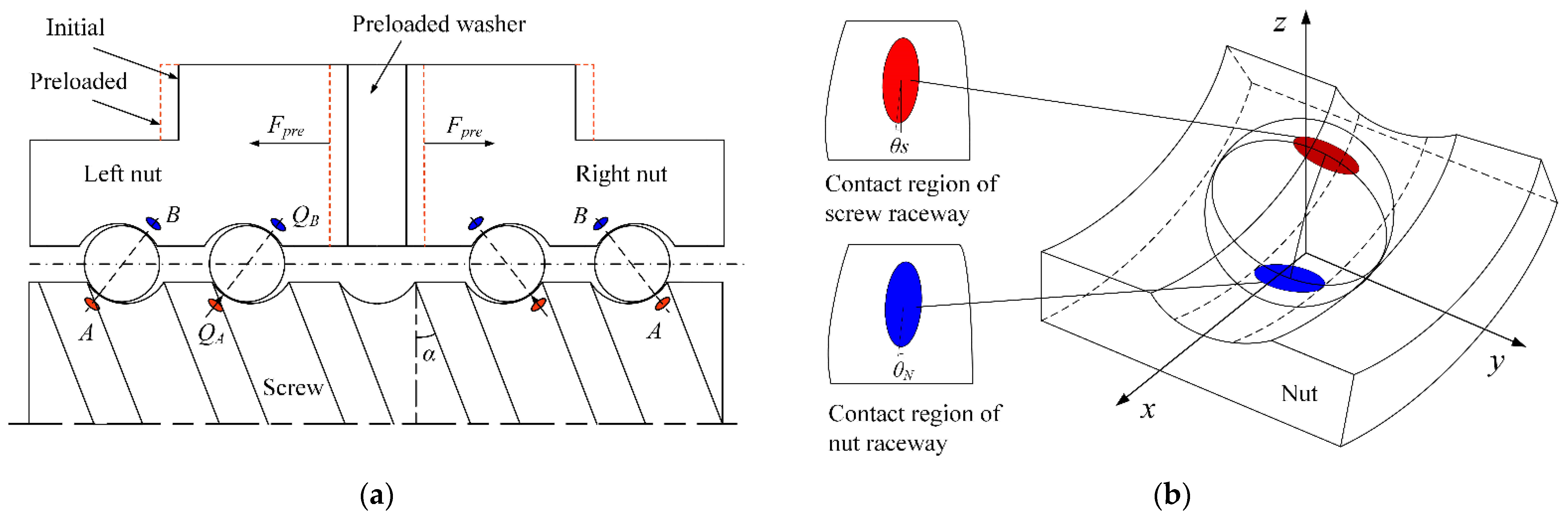
2.1. Analysis of Force and Motion
The positioning accuracy of DNBSs is determined by the preload provided by the preloaded washer. When the preload is applied, the working balls in the left nut and right nut are in a fully preloaded state due to the contact deformation of the left nut and right nut, respectively (Figure 1a). The static normal contact force at points A and B is expressed as
Figure 1.
Force analysis of ball screws. (a) Force balance analysis. (b) Contact mechanics analysis.
The DNBSs is operating at a constant speed; the working balls are in the balanced state of the force and torque, which comprise normal contact force, friction, inertia force, friction torque, and inertia torque. The balance equations of the force and torque of the ball are determined as
where QA and QB denote the normal contact force of the ball at the screw contact point A and the nut contact point B, respectively. FSA and FSB indicate the friction of the ball at the screw contact point A and the nut contact point B, respectively. FIH is the inertia force. MSA and MSB are the friction torque of the ball at the screw contact point A and the nut contact point B, respectively. MIH is the inertia torque. The parameters of DNBSs in the operating state, such as βA, βB, QA, QB, FSA, and FSB, are obtained by Equation (2) using the Newton iteration method. The specific solution process of the parameters of DNBSs can be observed in the reference [20]. The structural parameters of DNBSs are shown in Table 1.
Table 1.
Parameters of double-nut ball screws.
2.2. Non-Hertzian Normal Contact Stress Calculation
Due to the asymmetry of the contact region of the helical raceway of the high-speed BSs, there is a big error in the calculation of the contact stress distribution and contact region in the screw raceway contact point A and the nut raceway contact point B by using the traditional Hertzian contact theory. The non-Hertzian contact region between the ball and raceway is inclined compared with the Hertzian contact region, which is shown in Figure 1b. Based on the minimum excess principle, a method was proposed to analyze and calculate the normal contact stress between the ball and the raceway of the high-speed DNBSs.
In terms of the numerical solution process of the contact stress distribution between the ball and raceway, the contact region and deformation compatibility equation should be discretized. The contact gap and contact stress of the two contact surfaces should satisfy the following equation [21].
where c is the contact surface gap matrix. ci,j is the contact surface gap distribution in the mesh region, which is the element of the contact surface gap matrix c. d0 denote the approaching distance of the contact surface. cg is the contact surface geometry matrix. cgi,j indicates the contact surface geometry in the mesh region, which is the element of the contact surface geometry matrix cg. cr is the contact surface roughness matrix. cri,j is the contact surface roughness distribution, which is the element of the contact surface roughness matrix cr. V is the surface elastic deformation matrix. Vi,j is the surface elastic deformation distribution in the mesh region, which is the element of the surface elastic deformation matrix V. I and J indicate the mesh grid number in the x and y directions, respectively.
The discretized contact deformation equation is expressed as
where pi,j is the element of the contact stress matrix P. Ki − k,j − l is the element of deformation influence coefficient matrix K.
The boundary condition of the contact equation is expressed as
In the contact region, the boundary condition of the contact equation is ci,j = 0, pi,j ≥ 0; Out of the contact region, the boundary condition of the contact equation is ci,j > 0, pi,j = 0. According to the above two conditions, ci,j, and pi,j cannot be both zero, thus
The solution of the contact stress and the contact geometry is the key to the contact equation. The contact equation between the ball and raceway can be expressed by a matrix equation:
where ⊗ indicates cross product.
According to the variational principle, the contact problem described by Equations (7)–(9) can be transformed to the conditional extremum problem of quadratic function, which is derived by:
The boundary condition of Equation (10) is given by:
The fast convergence of the contact Equation (11) in the cyclic iteration is achieved by using the conjugate gradient method. The flowchart is shown in Figure 2. The detailed derived process and iteration solution process of the non-Hertzian contact stress is listed as follows [22]:
Figure 2.
Flowchart for the computation of the non-Hertzian contact stress.
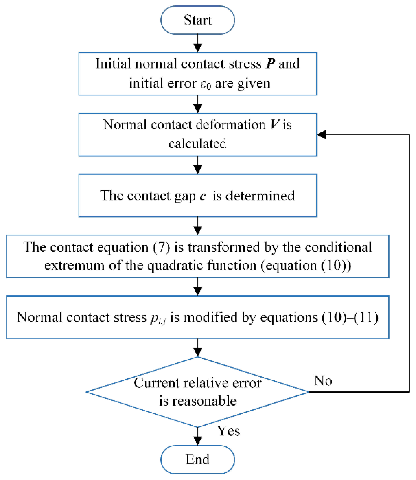
- The initial normal contact stress P is given, pi,j ≥ 0. The normal contact stress distribution pi,j is also satisfied in the mesh region.
- The discretized normal contact deformation V is determined by Equation (4).
- The contact gap c between the two contact surfaces is calculated by Equations (3)–(6), and the contact gap is satisfied with the boundary condition.
- According to the variational principle, the contact in Equation (7) can be transformed by the conditional extremum of the quadratic function, the normal contact stress pi,j is modified by Equation (10) satisfying the boundary condition in Equation (11).
- The current relative error is determined by:
- If ε ≥ ε0, the iteration solution process of the non-Hertzian contact stress continues from steps (2)–(5), otherwise the iteration solution process ends.
The classic solution between the ball and smooth plane can be determined by Hertzian contact theory [23]; it is expressed as
The comparison between the Hertzian solution and non-Hertzian solution of the contact stress under the helix angle is zero is shown in Figure 3. As shown in Figure 3, the non-Hertzian solution is in good agreement with the Hertzian solution in the contact stress calculation results, which is verified the correctness of the non-Hertzian contact stress calculation method.
Figure 3.
A comparison of the non-Hertzian and Hertzian solutions for the contact stress distribution between the ball and the screw raceway.
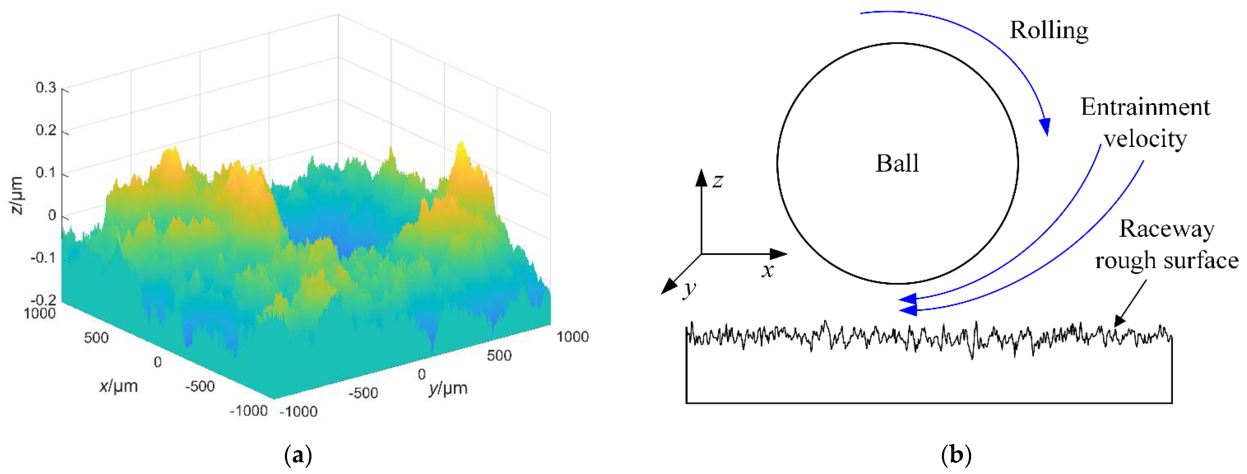
2.3. Non-Hertzian Elastohydrodynamic Contact Stress Calculation
The viscosity flow behavior of the lubricant film between the ball and raceway can be described by the Reynolds equation shown in Figure 4b. The initial film contact stress distribution in the Reynolds equation is the non-Hertzian contact stress distribution, which can further observe the variation of the elastohydrodynamic lubrication characteristics.
Figure 4.
Diagram of the elastohydrodynamic contact mechanics. (a) The fractal rough surface. (b) Elastohydrodynamic contact mechanics.
The assumptions of the Reynolds equation in the analysis are as follows:
- The lubricant and the solid are isothermal, and the contact stress and the film thickness do not vary with time.
- The curvature radius of the solid surface is much larger than the lubricant film thickness.
- No relative sliding between the lubricant film and solid surface at the common interface.
- Compared with the film shear stress, the inertial force and other bulk forces of the lubricant film are negligible.
- Due to the lubricant film thickness being very thin, it can be assumed that the film contact stress remains constant along the film thickness direction, namely no squeeze film effect.
- The inlet of the contact region is flooded fully by the lubricant film.
- The lubricant is the Newtonian fluid and obeys Newton’s law of viscosity.
The coupling relationship of the elastohydrodynamic contact stress distribution p, film thickness distribution h, film viscosity η, film density ρ, and film entrainment velocity us could be accurately determined by the Reynolds equation [24], which is written as
where p denotes the non-Hertzian elastohydrodynamic contact stress in the contact region. u1 and u2 indicate the linear velocity of the ball and the raceway in the tangential direction (x-direction) of the helix raceway track, respectively. The entrainment velocity of the lubricant film is us = (u1 + u2)/2. The output parameters of point A and point B calculated by Equation (2), such as QA, βA, QB, and βB, are substituted into the Reynolds Equation (14), the elastohydrodynamic characteristics of point A and point B can be determined, respectively.
In terms of the elastohydrodynamic lubrication theory [25], the film thickness distribution is expressed as
The lubricant film viscosity proposed by Roelands [26] is written as
The lubricant film density from Dowson and Higginson [27] is shown in Equation (17).
where h0 indicates the central film thickness in the contact region. η0 and ρ0 denote the initial value of the film viscosity and density, respectively. ROU(x,y) indicates the roughness of the contact surface calculated by the fractal theory [28] shown in Figure 4a. The major parameters of the rough fractal rough surface are the fractal dimension D and scale parameter G, D = 2.47, G = 0.41. The rough fractal surface is the contact region of the raceway. The hardness range of the ball is 62–64 HRC higher than that of the screw raceway 58–62 HRC; The processing technology of the working ball is mature, and the surface of the working ball is smooth. According to the above two reasons, the ball contact surface is regarded as a smooth surface. The surface roughness of the working ball is much less than that of the screw raceway. Therefore, the surface roughness of the ball has little effect on the calculation efficiency of this model.
Due to the film contact stress being largely influenced by the surface roughness, the contact surface roughness should be considered in the elastohydrodynamic contact system of BSs. In terms of the mature surface manufacturing technology of the ball, the ball contact surface can be seen as the smooth surface, and the raceway contact surface is the rough fractal surface (Figure 4a).
The boundary conditions of the Reynolds equation are written as
where xo and yo are the entrance coordinates of the contact region of BSs, respectively, and xe and ye are the exit coordinates of the contact region of BSs, respectively. The values of these coordinate parameters have been given: xo = yo = −277 μm, xe = ye = 277 μm.
The load balance condition of the Reynolds equation is expressed as
Substituting Equations (15)–(19) into Equation (14), the film contact stress distribution and the elastohydrodynamic contact stress distribution can be determined accurately by using the finite difference method [29,30], please see the Appendix A.
3. Experiments and Verification
To validate the correctness of elastohydrodynamic contact characteristics of the DNBSs by using the non-Hertzian contact stress calculation method. The friction torque of the DNBSs is measured by the self-designed bed, and the experimental friction torques are in good agreement with the simulated friction torques, which verifies the correctness of the non-Hertzian elastohydrodynamic contact stress calculation method.
3.1. Experiments Procedures
The experimental setup of the DNBSs is shown in Figure 5. The DNBSs was only applied with the preload in the experiment. The tension–compression sensor was mounted on the nut by the dowel bar. The friction torque of the BSs was measured under the experimental condition with constant preload Fpre = 1500 N, constant lubricating oil viscosity η0 = 0.05 Pa·s, and the different screw speeds. The simulated friction torque of the BSs can be expressed as
where FSBt and FSBb represent friction components at the directions of t and b in the Frenet–Serret coordinate system Otnb at point B, respectively [31]. nbb denotes the number of working balls.
Figure 5.
Experimental setup of the DNBSs. 1. Motor. 2. Coupling. 3. Base. 4. Guideway. 5. Table. 6. Screw. 7. Nut. 8. Clamping device. 9. Dowel bar. 10. Tension–compression sensor.
3.2. Experimental Results
The friction coefficient [32] of BSs can be written as
where Q is the total normal contact force, including the film bearing force Qf, and the asperity bearing force Qa. The ratio of the asperity bearing stress is RS, RS = Qa/Q. μa is the dry friction coefficient and μa = 0.1. τf is the film shear stress proposed by the Eyring model [33]. Ah is the film hydrodynamic contact area, η is the film viscosity, Δu is the relative sliding velocity, and Δu = u1 − u2. u1 and u2 are the same as that of Equation (14). h0 is the film central thickness.
The results of the friction torque test are shown in Figure 6. The friction coefficient curve of the DNBSs is indicated by the blue lines in Figure 6b, which is in good agreement with the schematic Stribeck curve [34] shown in the green box (Figure 6a). The friction coefficient is composed of the asperity friction coefficient and the hydrodynamic lubrication friction coefficient. When the screw speed is lower than 502.65 mm/s, the BSs is in the mixed lubrication state. When the screw speed is higher than or equal to 502.65 mm/s, the BSs is in the hydrodynamic lubrication state. The comparison of the simulated and experimental friction torque is shown in Figure 6c. The comparisons showed that the experimental friction torque was consistent with the simulated friction torque, which verified the correctness of the non-Hertzian elastohydrodynamic contact stress calculation method.
Figure 6.
Results of the friction torque test. (a) A schematic Stribeck curve [34]. (b) Friction coefficient curve. (c) Comparison of the simulated and experimental friction torque.
4. Results Analysis and Discussion
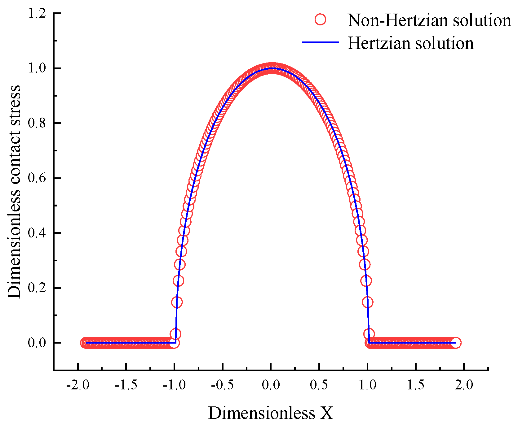
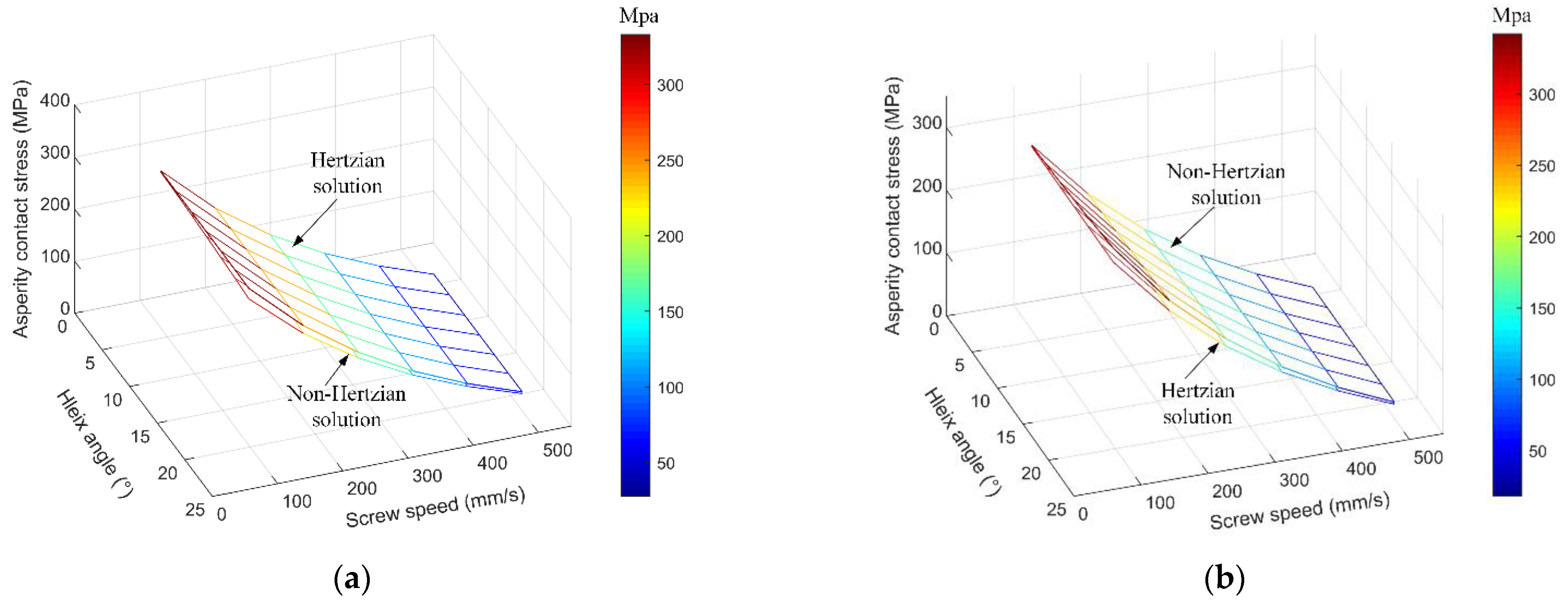
4.1. Comparison of the Normal Contact Stress between Hertzian Solution and Non-Hertzian Solution
In order to determine the contact stress distribution of DNBSs accurately, the contact stress distributions between the ball and raceway are calculated by the minimum excess principle and Hertzian contact theory, respectively. The calculation results by the two methods are analyzed comparatively.
The contact stress distribution of DNBSs is calculated under the preload Fpre is 1500 N, and the helix angle α is 21.7°. The contact stress comparison between the Hertzian solution and non-Hertzian solution of BSs is shown in Figure 7. As shown in Figure 7, the difference contour maps between the Hertzian solution and non-Hertzian solution at contact point A and contact point B indicate the great difference between the two calculation methods. The difference of the contact stress in the edge of the contact region is the largest, and the one in the center of the contact region is the smallest. Thus, there is a big error of contact stress distribution calculated by the Hertzian contact theory, and the contact stress distribution calculated by the non-Hertzian solution is more accurate.
Figure 7.
The contact stress distribution comparison between the Hertzian solution and the non-Hertzian solution. (a) Contact stress solution at the ball/screw–raceway point A. (b) Contact stress solution at the ball/nut raceway point B.
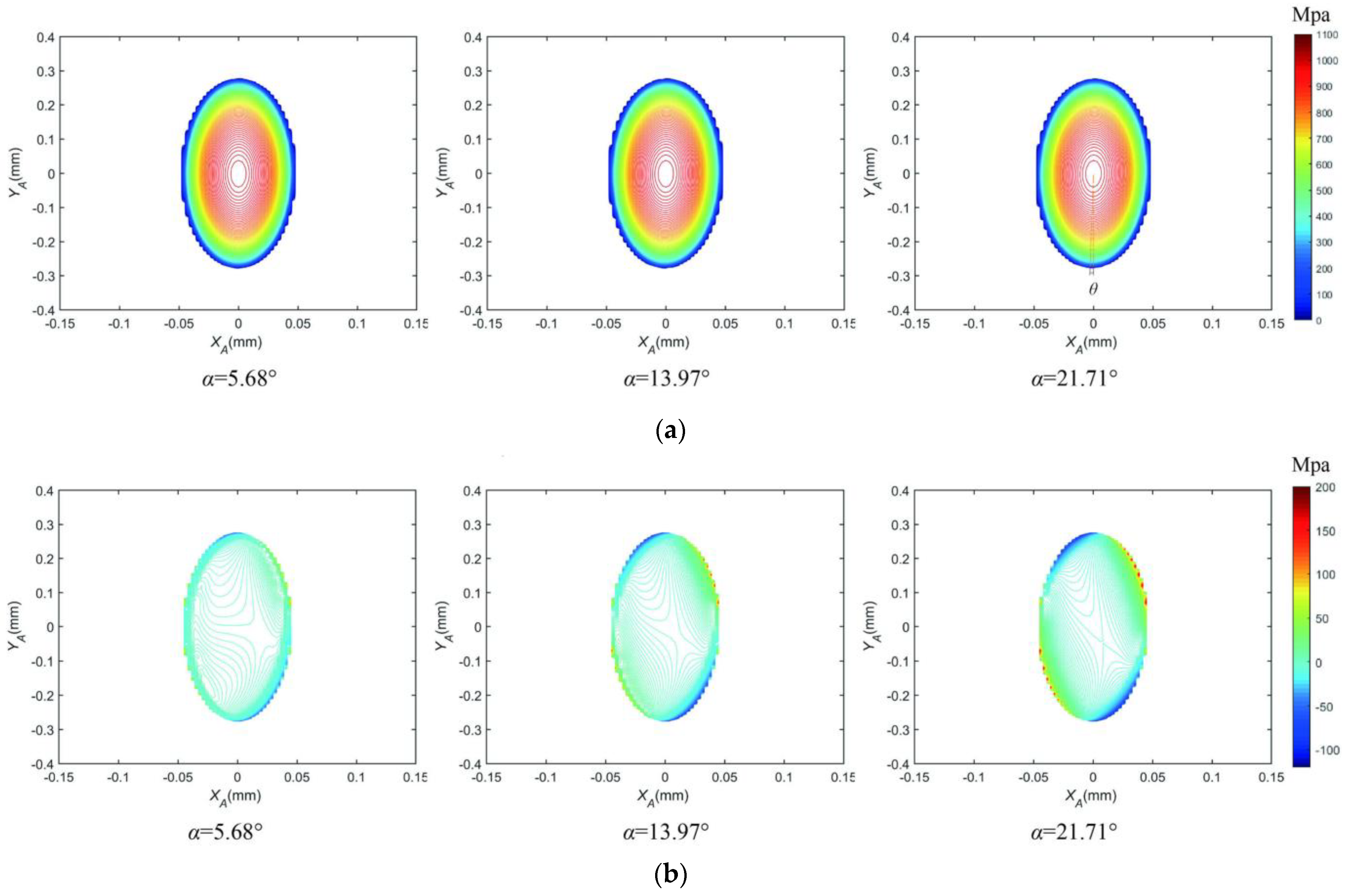
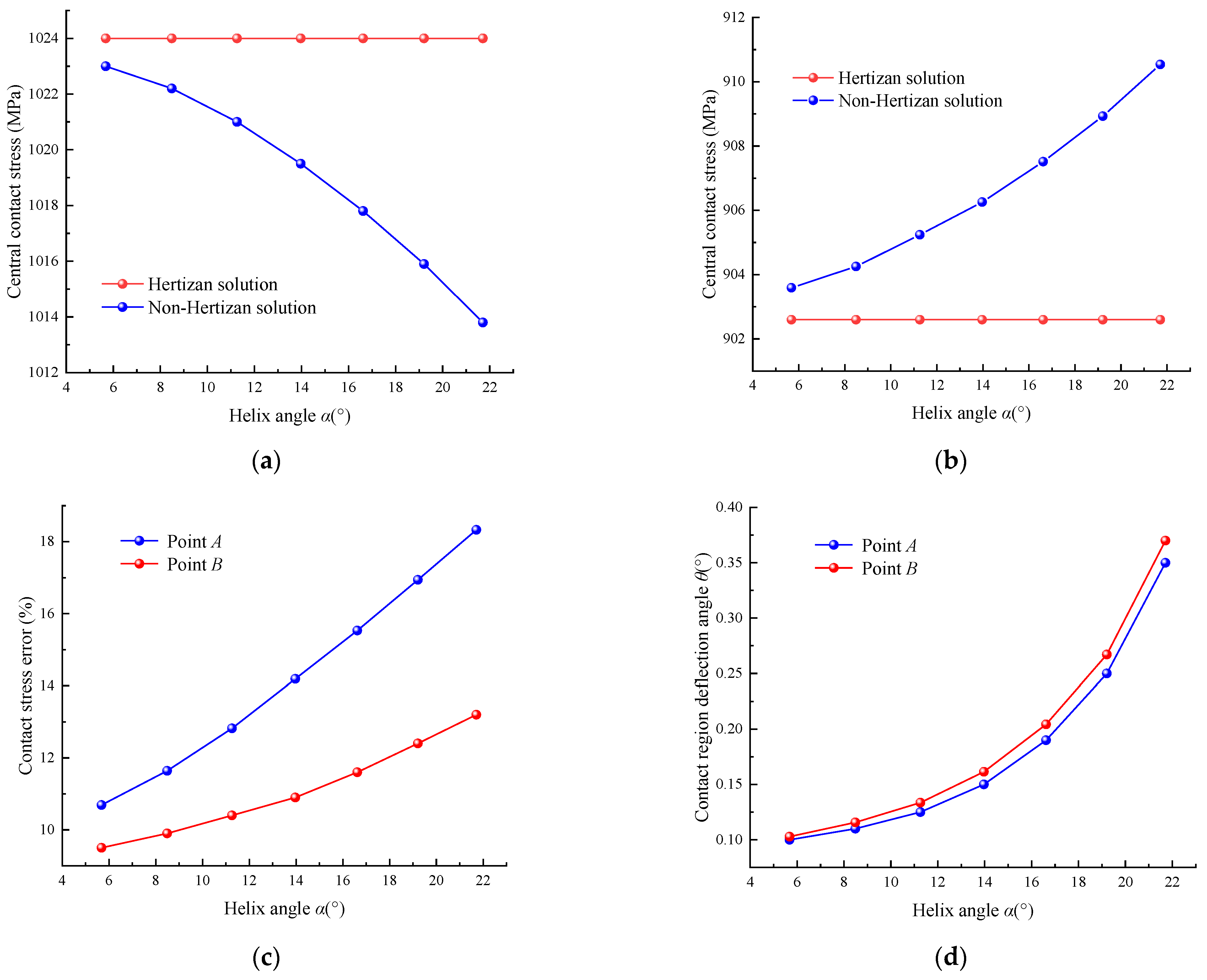
4.2. Analysis of the Non-Hertzian Contact Stress with Different Helix Angles
In order to further analyze the effect of contact stress error calculated by the Hertzian contact theory with the variation of the helix angle, the contact stress difference contour maps at the screw raceway contact point A under the helix angle α are 5.68°, 13.97°, and 21.71° are determined, respectively. The elliptical contact region of non-Hertzian solution PA at the contact point A generates a deflection angle θs shown in Figure 8a. The contact stress distribution difference PA-PAH between the non-Hertzian solution PA and the Hertzian solution PAH in the edge of the contact region is largest, and the one in the center of the contact region is smallest shown in Figure 8b.
Figure 8.
The variation of the non-Hertzian contact stress with different helix angles. (a) Contour map of non-Hertzian contact pressure distribution PA (Mpa). (b) Distribution difference between non-Hertzian contact pressure and Hertzian contact pressure PA-PAH (Mpa).
Figure 9a,b shows that the central contact stress of the Hertzian solution does not change with the increase in the helix angle; the central contact stress of the non-Hertzian solution at contact point A decreases with the increase in the helix angle, and the one at contact point B increases with the increase in the helix angle. As shown in Figure 9c, the central contact stress errors of point A and point B increase as the helix angle. The central contact stress error of point A is larger than the one of point B, and the gap of the central contact stress error between point A and point B increases as the helix angle. The contact region deflection angles of point A and point B increase with the increase in the helix angle due to the difference of the structural parameters between the screw raceway and nut raceway, which is shown in Figure 9d.
Figure 9.
Comparison of the Hertzian and non-Hertzian contact stress. (a) The central contact stress of the point A. (b) The central contact stress of the point B. (c) The contact stress error. (d) The contact region deflection angle.
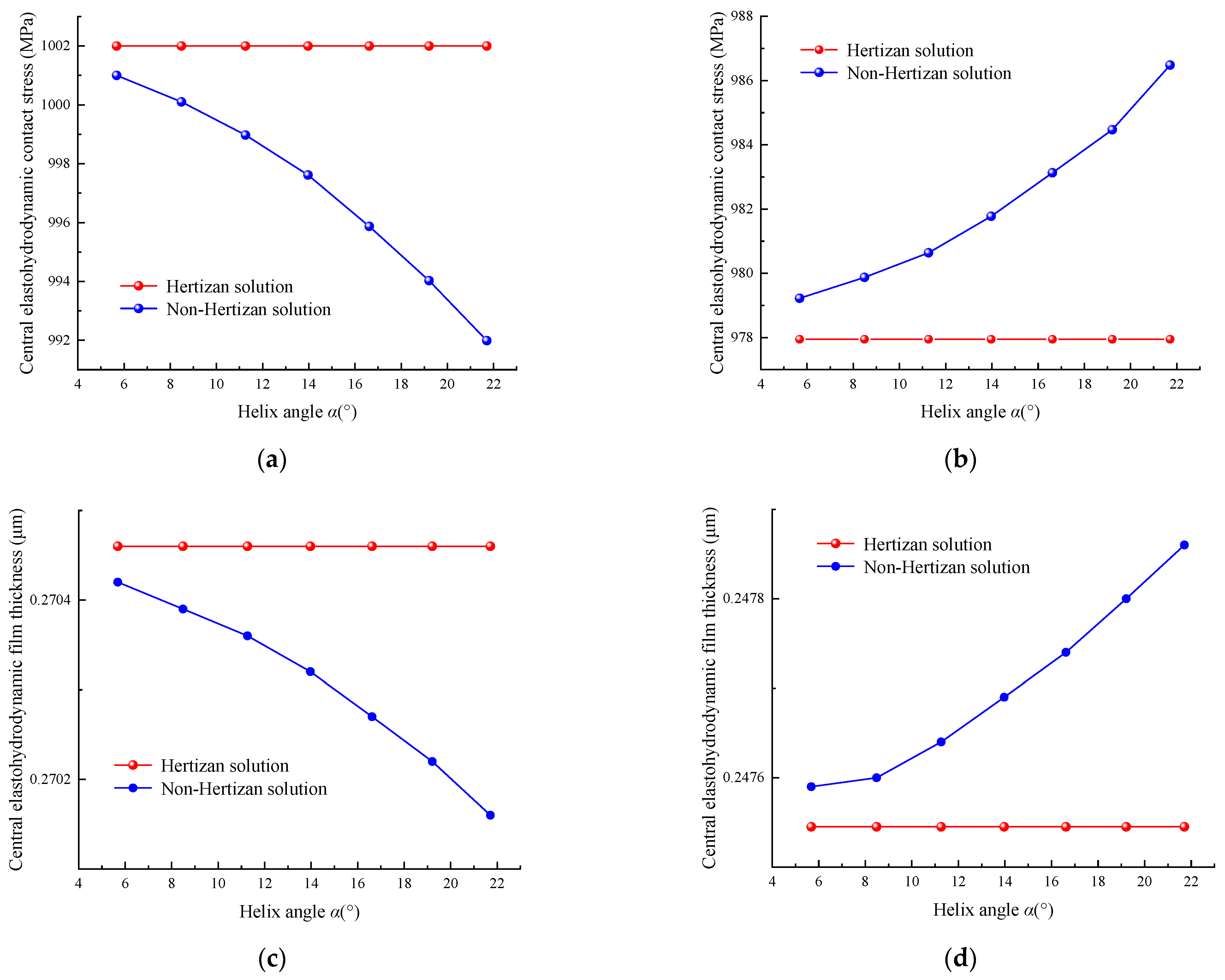
4.3. Analysis of the Elastohydrodynamic Contact Stress with Different Helix Angles
The elastohydrodynamic characteristics of point A under the preload are 1500 N and the entrainment velocity is 1005.3 mm/s, which are shown in Figure 10. When the lubricant film is entrained into the contact region, the secondary peak of the film contact stress in the exit coordinates of the contact region is generated, as shown in Figure 10a. Figure 10b shows the film thickness distribution of point A.
Figure 10.
Elastohydrodynamic characteristics using the non-Hertzian contact stress calculation method. (a) Elastohydrodynamic contact stress distribution. (b) Film thickness distribution.
Figure 11a,b show that the variations of central elastohydrodynamic contact stress calculated by the Hertzian solution and non-Hertzian solution with different helix angles, respectively. The variation trends of the central elastohydrodynamic contact stress of point A and point B are the same. However, the values of the central elastohydrodynamic contact stress are greater than that of the central contact stress of point A and point B.
Figure 11.
Comparison of the elastohydrodynamic characteristics between the Hertzian solution and non-Hertzian solution. (a) Central elastohydrodynamic contact stress of point A. (b) Central elastohydrodynamic contact stress of point B. (c) Central elastohydrodynamic film thickness of point A. (d) Central elastohydrodynamic film thickness of point B.
Figure 11c,d show that the variations of central elastohydrodynamic film thickness calculated by the Hertzian solution and non-Hertzian solution with different helix angles, respectively. The elastohydrodynamic film thickness of non-Hertzian solution at point A decreases as the helix angle, else the one at point B increases as the helix angle, which indicates that the lubrication state of the nut contact point B is good than the screw contact point A.
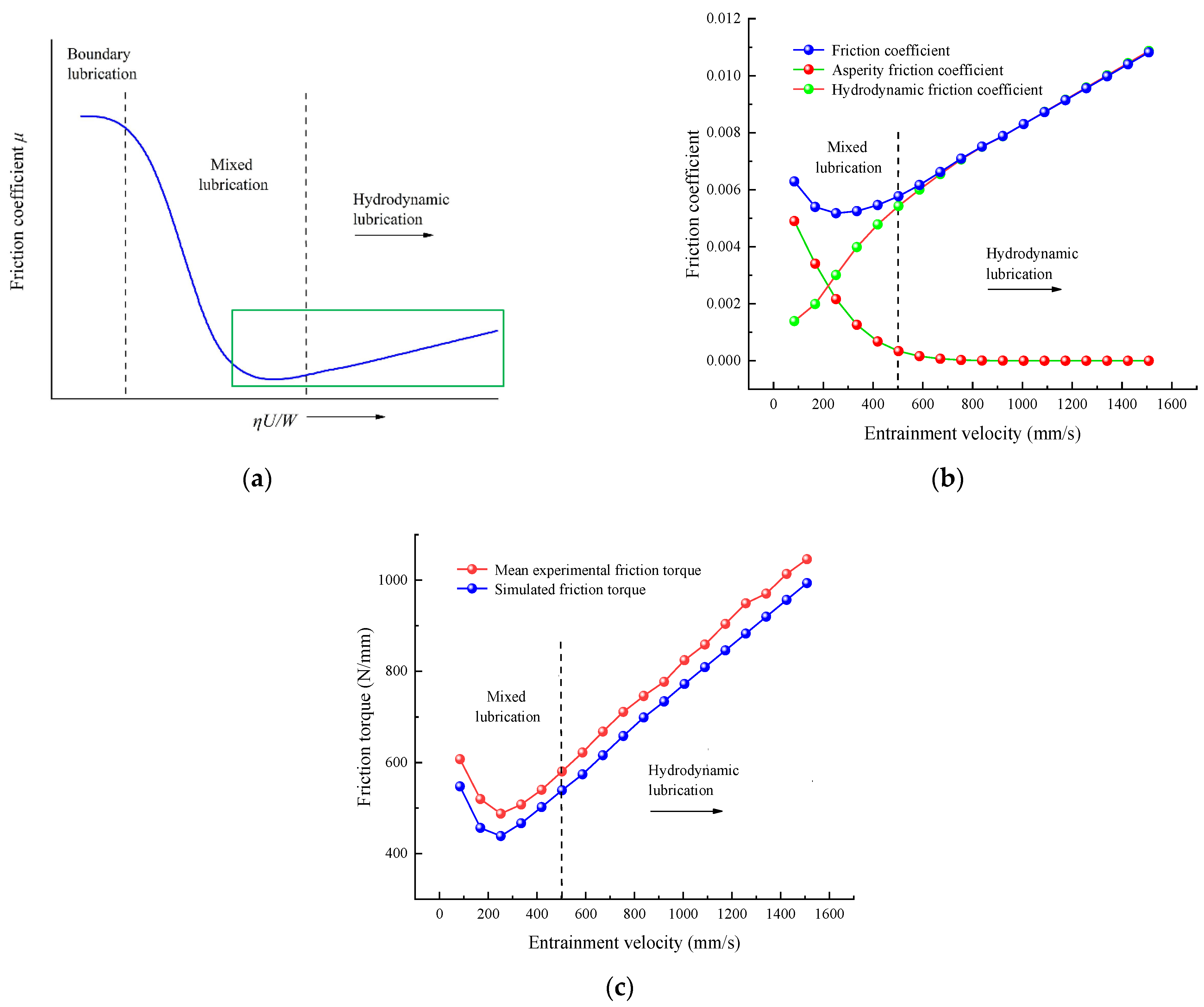
4.4. Effect of the Elastohydrodynamic Contact Stress under Different Screw Speeds
The central elastohydrodynamic contact stresses of the BSs under different helix angles and different screw speeds are shown in Figure 12. As shown in Figure 12a, the non-Hertzian solution is smaller than the Hertzian solution of the central elastohydrodynamic contact stress at contact point A. The central elastohydrodynamic contact stress decreases with the increase in the helix angle and the screw speed, respectively. As shown in Figure 12b, the non-Hertzian solution is greater than the Hertzian solution of the central elastohydrodynamic contact stress at contact point B. The central elastohydrodynamic contact stress increases as the helix angle increases, and decreases as the screw speed increases.
Figure 12.
Comparison of the elastohydrodynamic stress between the Hertzian solution and non-Hertzian solution under different screw speeds. (a) Central elastohydrodynamic contact stress of point A. (b) Central elastohydrodynamic contact stress of point B.
The wear depth and wear rate of the BSs are mainly influenced by the asperity contact stress. The asperity contact stresses in the elliptical contact region of the BSs under different helix angles and different screw speeds are shown in Figure 13. The law of the asperity contact stress of points A and B is the same as that of the elastohydrodynamic contact stress of points A and B. Under the helix angle of 21.71°, the calculation accuracies of asperity contact stress for the non-Hertzian solution are 2.93% and 3.01% more accurate than that of the Hertzian solution at the screw-raceway contact region and the nut–raceway contact region, respectively.
Figure 13.
Comparison of the asperity contact stress between the Hertzian solution and non-Hertzian solution under different screw speeds. (a) Central asperity contact stress of point A. (b) Central asperity contact stress of point B.
5. Conclusions
Due to the obvious asymmetry of the raceway contact region of the high-speed BSs, a non-Hertzian elastohydrodynamic contact stress calculation method based on the minimum excess principle is proposed, and the conclusions below can be drawn:
(1) The normal contact stress error between the Hertzian solution and the non-Hertzian solution increases as the helix angle, and the contact stress error of the screw raceway contact region is always greater than that of the nut raceway contact region.
(2) The non-Hertzian elastohydrodynamic contact stress of the BSs show different trends in the contact regions of the screw raceway and nut raceway with the increase of the helix angle and screw speed, respectively. The non-Hertzian solution is smaller than the Hertzian solution of the central elastohydrodynamic contact stress at the screw raceway contact region. However, the non-Hertzian solution is greater than the Hertzian solution of the central elastohydrodynamic contact stress at the nut raceway contact region.
(3) The positioning accuracy of the DNBSs is obviously influenced by the wear of the raceway due to the asperity contact problem. Under the helix angle of 21.71°, the calculation accuracies of asperity contact stress for the non-Hertzian solution are 2.93% and 3.01% more accurate than that of the Hertzian solution at the screw raceway contact region and the nut raceway contact region, respectively. Therefore, the non-Hertzian elastohydrodynamic contact stress calculation method is essential to precisely analyze the wear mechanism of the high-speed BSs.
Author Contributions
T.S. proposed and simulated the calculation method, designed the experiment, and wrote the paper. X.G. implemented the experiment. M.W. guided the general idea of this paper. Y.Z. analyzed the experimental data. All authors have read and agreed to the published version of the manuscript.
Funding
This study was sponsored by the National Natural Science Foundation of China (No. 51975020, 51575014 and 51875008), Beijing Municipal Natural Science Foundation (No. 3202005), and the International Research Cooperation Seed Fund of Beijing University of Technology (No. 2021A10).
Conflicts of Interest
The authors declare no conflict of interest.
Glossary
| a | Major axis of the elliptical contact region/mm |
| b | Minor axis of the elliptical contact region/mm |
| c | Contact gap between the two contact surfaces/mm |
| d | Approaching distance of the contact surface/mm |
| h | Lubricant film thickness/μm |
| n | Number of the working ball |
| p | Normal contact stress/MPa |
| r | Radius/mm |
| u | Entrainment velocity/(mm/s) |
| x, y, z | Coordinates in ball screws |
| A | Area/(μm2) |
| D | Fractal dimension |
| E | Elasticity modulus/MPa |
| F | Force/N |
| G | Scale parameters |
| K | Deformation influence coefficient/(mm/N) |
| I, J | Total number in the x or y direction |
| L | Pitch of the screw/mm |
| M | Torque/(N/mm) |
| Q | Load/N |
| R | The ratio of the asperity bearing stress |
| ROU | Profile of the rough surface/μm |
| V | Contact deformation/mm |
| W | Quadratic function |
| α | Helix angle/° |
| β | Contact angle/° |
| ε | Iteration precision |
| θ | Deflection angle of the contact region/° |
| υ | Poisson ratio |
| τ | Lubricant film shear stress/MPa |
| ρ | Lubricant film density/(kg/m3) |
| η | Lubricant film viscosity/(Pa·s) |
| μ | Friction coefficient |
| Ω’ | Screw speed/(mm/s) |
Nomenclature
| 0 | Initial value |
| 1, 2 | The two contact surfaces |
| a | Asperity bearing |
| bb | Ball |
| f | Lubricant film bearing |
| g | Contact gap |
| h | Mesh region |
| i, j | Column or row number |
| pre | Preload |
| t, n, b | Coordinates in OHtnb |
| o, e | Entrance and exit coordinates of the contact region |
| A | Contact point between ball and screw raceway |
| AH | Contact point between ball and screw raceway with Hertzian contact |
| B | Contact point between ball and nut raceway |
| BH | Contact point between ball and nut raceway with Hertzian contact |
| IH | Inertia |
| S | Screw |
| SA | Friction between ball and screw raceway |
| SB | Friction between ball and nut raceway |
| N | Nut |
Abbreviations
| BSs | Ball screws |
| DNBSs | Double-nut ball screws |
| EHL | Elastohydrodynamic lubrication |
| NC | Numerical control |
Appendix A
The Finite Difference Method
The finite difference method is an approximation method for solving the numerical solution for differential equations. The main principle of the finite difference method is to make a direct difference approximation to the differential term in the differential equation, thus transforming the differential equation into the algebraic equation for the solution. Due to the advantages of conceptual clarity, generality, and ease of implementation on computers, the finite difference method is widely used in the field of differential equation solving. Therefore, the Reynolds equation describing the elastohydrodynamic contact characteristics of the lubricant film of DNBSs under different operating conditions is determined by the finite difference method in this paper.
References
- Zhang, G.; Jin, H.; Lin, Y.-J. Attaining Ultraprecision Machining by Feed Drive System Stability Control with Piezoelectric Preloading Actuators. Appl. Sci. 2021, 11, 8491. [Google Scholar] [CrossRef]
- Chen, Y.; Zhao, C.; Li, Z.; Lu, Z. Analysis on Dynamic Contact Characteristics and Dynamic Stiffness Estimating Method of Single Nut Ball Screw Pair Based on the Whole Rolling Elements Model. Appl. Sci. 2020, 10, 5795. [Google Scholar] [CrossRef]
- Liu, J.; Feng, H.; Zhou, C. Static load distribution and axial static contact stiffness of a preloaded double-nut ball screw considering geometric errors. Mech. Mach. Theory 2022, 167, 104460. [Google Scholar] [CrossRef]
- Lin, B.; Okwudire, C.E.; Wou, J.S. Low Order Static Load Distribution Model for Ball Screw Mechanisms Including Effects of Lateral Deformation and Geometric Errors. J. Mech. Des. 2018, 140, 12. [Google Scholar] [CrossRef]
- Liu, C.; Zhao, C.; Meng, X.; Wen, B. Static load distribution analysis of ball screws with nut position variation. Mech. Mach. Theory 2020, 151, 103893. [Google Scholar] [CrossRef]
- Huang, Y.-C.; Kao, C.-H.; Chen, S.-J. Diagnosis of the Hollow Ball Screw Preload Classification Using Machine Learning. Appl. Sci. 2018, 8, 1072. [Google Scholar] [CrossRef] [Green Version]
- Zhen, N.; An, Q. Analysis of stress and fatigue life of ball screw with considering the dimension errors of balls. Int. J. Mech. Sci. 2018, 137, 68–76. [Google Scholar] [CrossRef]
- Miura, T.; Matsubara, A.; Kono, D.; Otaka, K.; Hoshide, K. Design of high-precision ball screw based on small-ball concept. Precis. Eng. 2017, 47, 452–458. [Google Scholar] [CrossRef]
- Bertolino, A.C.; Jacazio, G.; Mauro, S.; Sorli, M. Investigation on the ball screws no-load drag torque in presence of lubrication through MBD simulations. Mech. Mach. Theory 2021, 161, 104328. [Google Scholar] [CrossRef]
- Su, J.; Song, H.-X.; Ke, L.-L. Elastohydrodynamic lubrication line contact in couple-stress elasticity. Math. Mech. Solids 2021, 26, 1053–1073. [Google Scholar] [CrossRef]
- Pei, J.; Han, X.; Tao, Y.; Feng, S. Mixed elastohydrodynamic lubrication analysis of line contact with Non-Gaussian surface roughness. Tribol. Int. 2020, 151, 106449. [Google Scholar] [CrossRef]
- Clarke, A.; Jamali, H.; Sharif, K.; Evans, H.; Frazer, R.; Shaw, B. Effects of profile errors on lubrication performance of helical gears. Tribol. Int. 2017, 111, 184–191. [Google Scholar] [CrossRef]
- Sharif, K.J.; Evans, H.P.; Snidle, R.W.; Barnett, D.; Egorov, I.M. Effect of elastohydrodynamic film thickness on a wear model for worm gears. In Proceedings of the Institution of Mechanical Engineers, Part J: Journal of Engineering Tribology; SAGE Publications: Southend Oaks, CA, USA, 2006; Volume 220, pp. 295–306. [Google Scholar]
- Sharif, K.; Evans, H.; Snidle, R. Prediction of the wear pattern in worm gears. Wear 2006, 261, 666–673. [Google Scholar] [CrossRef]
- Wei, C.C.; Lin, J.F.; Horng, J.-H. Analysis of a ball screw with a preload and lubrication. Tribol. Int. 2009, 42, 1816–1831. [Google Scholar] [CrossRef]
- Otsu, T.; Komatsu, K.; Hashimura, S.; Imado, K. Shear properties under the starved condition of polyisobutylene lubricant for use in screw tightening-effect of operating condition on lubrication properties. Tribol. Int. 2018, 122, 133–142. [Google Scholar] [CrossRef]
- Fleischer, J.; Spohrer, A.; Leberle, U.; Dosch, S. Adaptive and Adequate Lubrication for Highest Component-lifetimes in Feed Drive Axes with Ball Screws. Procedia CIRP 2015, 29, 335–340. [Google Scholar] [CrossRef]
- Xie, Z.; Xue, Q.; Wu, J.; Gu, L.; Wang, L.; Song, B. Mixed-lubrication analysis of planetary roller screw. Tribol. Int. 2019, 140, 105883. [Google Scholar] [CrossRef]
- Oh, K.-J.; Cao, L.; Chung, S.-C. Explicit modeling and investigation of friction torques in double-nut ball screws for the precision design of ball screw feed drives. Tribol. Int. 2020, 141, 105841. [Google Scholar] [CrossRef]
- Zhou, H.-X.; Zhou, C.-G.; Feng, H.-T.; Ou, Y. Theoretical and experimental analysis of the preload degradation of double-nut ball screws. Precis. Eng. 2020, 65, 72–90. [Google Scholar] [CrossRef]
- Wang, W.; Hu, Y.; Wang, H. Numerical solution of dry contact problem based on fast Fourier transform and conjugate gradient method. Chin. J. Mech. Eng. 2006, 42, 14–18. [Google Scholar] [CrossRef]
- Brandt, A.; Lubrecht, A. Multilevel matrix multiplication and fast solution of integral equations. J. Comput. Phys. 1990, 90, 348–370. [Google Scholar] [CrossRef]
- Wang, M.; Sun, T.; Dong, Z.; Kong, D.; Gao, X. Non-Hertzian Contact Stress Calculation of High-speed Ball Screw Mechanism. Adv. Eng. Sci. 2021, 53, 178–186. [Google Scholar]
- Hu, Y.-Z.; Zhu, D. A Full Numerical Solution to the Mixed Lubrication in Point Contacts. J. Tribol. 1999, 122, 1–9. [Google Scholar] [CrossRef]
- Gao, X.-S.; Wang, M.; Liu, X.-B. Modeling and application of thermal contact resistance of ball screws. J. Central South Univ. 2019, 26, 168–183. [Google Scholar] [CrossRef]
- Roelands, C.J.A. Correlation aspect of the viscosity-temperature-pressure relation of lubrication oil. Ph.D. Thesis, Delft University of Technology, Delft, The Netherlands, 1966. [Google Scholar]
- Dowson, D.; Higginson, G.R. Elastohydrodynamic Lubrication; Pergamon Press: Oxford, UK, 1966. [Google Scholar]
- Ausloos, M.; Berman, D.H. A multivariate Weierstrass–Mandelbrot function. In Proceedings of the Royal Society of London Series A, Mathematical and Physical Sciences; Royal Society: London, UK, 1985; Volume 400, pp. 331–350. [Google Scholar] [CrossRef]
- Zhu, D.; Wang, Q.J. Effect of Roughness Orientation on the Elastohydrodynamic Lubrication Film Thickness. J. Tribol. 2013, 135, 031501. [Google Scholar] [CrossRef]
- Wang, W.-Z.; Liu, Y.-C.; Wang, H.; Hu, Y.-Z. A Computer Thermal Model of Mixed Lubrication in Point Contacts. J. Tribol. 2004, 126, 162–170. [Google Scholar] [CrossRef]
- Hu, J.; Wang, M.; Zan, T. The kinematics of ball-screw mechanisms via the slide–roll ratio. Mech. Mach. Theory 2014, 79, 158–172. [Google Scholar] [CrossRef]
- Han, Y. Research on Identification and Control Compensation of Friction in Sero Feed System of CNC Machine Tool; Harbin Institute of Technology: Harbin, China, 2017. (In Chinese) [Google Scholar]
- Bair, S. Actual Eyring Models for Thixotropy and Shear-Thinning: Experimental Validation and Application to EHD. J. Tribol. 2004, 126, 728–732. [Google Scholar] [CrossRef]
- Wang, W.-Z.; Wang, S.; Shi, F.; Wang, Y.-C.; Chen, H.-B.; Wang, H.; Hu, Y.-Z. Simulations and Measurements of Sliding Friction between Rough Surfaces in Point Contacts: From EHL to Boundary Lubrication. J. Tribol. 2007, 129, 495–501. [Google Scholar] [CrossRef]
Publisher’s Note: MDPI stays neutral with regard to jurisdictional claims in published maps and institutional affiliations. |
© 2021 by the authors. Licensee MDPI, Basel, Switzerland. This article is an open access article distributed under the terms and conditions of the Creative Commons Attribution (CC BY) license (https://creativecommons.org/licenses/by/4.0/).