Article

Positioning Errors Measurement of CNC Machine Tools Based on J-DBB Method

School of Mechanical Engineering, Hangzhou Dianzi University, Hangzhou 310018, China
*
Authors to whom correspondence should be addressed.
Appl. Sci. 2021, 11(24), 11770; https://doi.org/10.3390/app112411770
Submission received: 12 October 2021 / Revised: 26 November 2021 / Accepted: 6 December 2021 / Published: 10 December 2021
(This article belongs to the Special Issue Precision Manufacturing and Intelligent Machine Tools)

Abstract

:
Due to the errors of the servo system and the errors of the ball screw drive system, the positioning errors inevitably occur in the process of CNC machine tools. The measurement of traditional equipment is limited by a fixed measurement radius and a single degree of freedom, which can only be measured within a fixed plane. In this paper, four different positioning errors of CNC machine tools are first measured at full scale by using J-DBB (a modified double ball bar with one spherical joint connecting two bars) method. The J-DBB device uses a three-degree-of-freedom spherical joint as a connecting part, which realizes that the measurement radius can be continuously changed, and the measurement space is a spatial sphere. First, the principle of the J-DBB method is briefly introduced. Next, four typical positioning errors of CNC machine tools are analyzed and examined, which contain the uniform contraction error of ball screw and linear grating, periodic error of the ball screw and linear grating, interference of measurement devices error, and opposite clearance error. In the end, the trajectories of the CNC machine tool spindle with a single positioning error are simulated by using the J-DBB method. The results reveal that this method can be used for the positioning error of machine tools, which helps to better understand the spatial distribution of CNC machine tool errors and provides guidance for the reasonable selection of working areas to improve the machining accuracy of parts.

1. Introduction

Machining parts with high accuracy is a key issue in the field of precision manufacturing. The emergence of CNC machine tools provides the possibility to process high-accuracy parts [1,2]. Due to the increasingly high precision requirements of parts in modern processing and manufacturing industries, CNC machine tools are facing the challenge of achieving high-precision machining on complex parts [3]. The factors that affect the accuracy of CNC machine tools can be broadly divided into geometric errors, thermal induction errors, and positioning errors [4,5]. Double ball bar (DBB) has been widely used in the error measurement of NC machine tools since it was proposed [6,7]. DBB measures the movement errors of the machine tool through a displacement sensor. Compared with other measurement methods, DBB has higher measurement accuracy, easier operation, and is more convenient [8], so scholars have done a lot of research on the use of DBB to measure machine tool errors.
The volume error of the vertical machining center was analyzed using DBB [9]. The errors of the rotary axis of a five-axis CNC machine tool were measured using a fixed-length DBB [10,11]. The accuracy of the machine tool was evaluated using DBB under no-load conditions [12,13]. A measurement technique based on telescopic DBB is proposed to measure the thermal error of CNC machine tools [14]. A kinematic calibration method for five DOF and six DOF in-parallel actuated mechanisms was proposed based on DBB [15]. The volume error model of the coordinate measuring machine based on DBB was established, and the validity was verified by the compensation experiment [16]. However, DBB is a single degree of freedom measuring instrument; in the above studies, data collection can be completed only through multiple measurements in different positions or directions, which cannot meet the needs of efficient measurement.
Many new devices based on the DBB method were designed to better measure the error of machine tools. The telescoping magnetic ball bar (TMBB) has been provided to detect the motion errors of the machine tool [17], but due to the limitation of the structure, the measurement accuracy is not high enough. An instrument that utilizes three rotary encoders and link mechanisms (RELM) has been developed to measure the motion accuracy of the CNC machine tools [18]. Its measurement radius is constant, and the measurement efficiency is low. The double rings string (DRS) method was studied to estimate the error of large-scale machine tools. However, the accuracy of DRS was slightly lower [19]. A linkage bar mechanism composed of rotary encoder was proposed to improve the measurement accuracy of machine tool motion error [20,21]. This new device with a variably measuring radius can largely extend the measurement ranges. Nevertheless, the measuring capability of the device is limited to a plane in a fixed direction. The linked ball bar (LBB) is developed to measure machine tool motion errors in a plane [22]. The device using two link bars solved the problem of the short measurement range of DBB and has high measurement accuracy. The double ball bar with a spherical joint (J-DBB) was developed to measure machine tool motion errors of the arbitrary space path [23]. Compared with the DBB that only measures on the plane, the J-DBB method reflects the spatial error of the machine tool through the space angle between the two bars, which is more in line with the real error measurement requirements of the machine tool. However, there is currently no comprehensive method for measuring spatial angles, so this paper decouples the spatial angles into two plane angles to verify the feasibility of the J-DBB method. The J-DBB device has a flexible measuring range and was used to measure five geometric errors of the machine tools. These five geometric errors are related to the shape errors of the machine tool guide rail. This type of error is caused by machining errors of the guide rail, improper assembly of the guide rail, the thermal deformation of the guide rail, the incorrect initial installation position of the guide rail is incorrect, etc.
The positioning errors such as the uniformity contraction error and opposite clearance error of the ball screw will significantly reduce the motion accuracy of the machine tools [24,25,26]. The positioning errors are related to the positioning mechanism and the servo control system. The errors of the positioning mechanism mainly include the uniform contraction error of the ball screw, the periodic error caused by the pitch error, vibration, and installation error of the ball screw. Opposite clearance error caused by servo system out-of-step and inaccurate numerical control compensation. To continue to improve the accuracy of the machine tool, the measurement of positioning errors is indispensable [27,28,29,30]. However, the above-mentioned positioning errors have not been thoroughly studied. In addition, the J-DBB is a new device for the geometric errors of machine tools. Therefore, it’s necessary to further study the positioning errors of machine tools based on the J-DBB method.
This paper measured the positioning errors of the CNC machine tool at full scale using the J-DBB method. This paper is organized as follows: Section 2 introduces the basic principle of the J-DBB method. Section 3 analyzes four typical positioning errors of the CNC machine tool. Section 4 simulates these positioning errors and analyzes the results. The rest summarizes the advantages and measurement methods.

2. Principle of the J-DBB

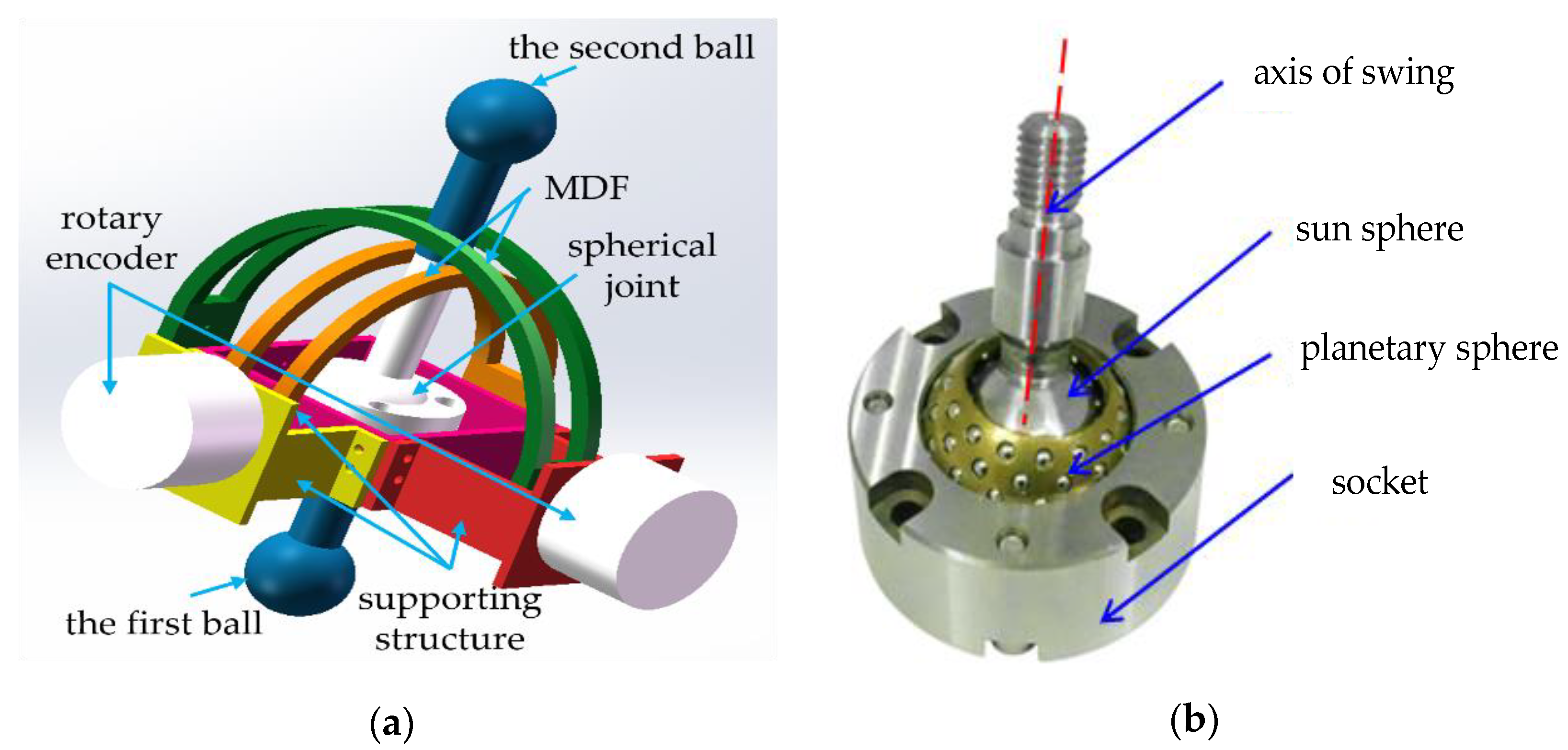
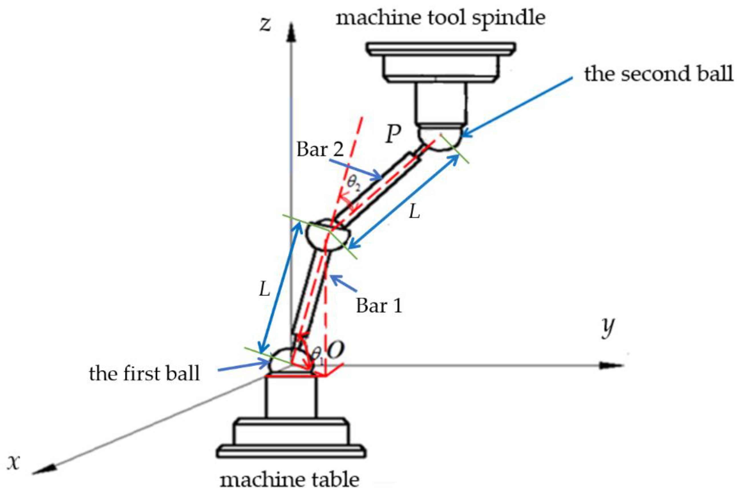
2.1. Structure of the J-DBB

Generally, the length of the bar in traditional DBB is constant. Several bars with different lengths are required for different errors measurement radius of the machine tool. The limited work scope and discontinuous error measurement radius have afflicted scholars and mechanical engineers for several decades. A new device named J-DBB with a freely measuring radius was proposed to measure the errors of the CNC machine tool [23]. As shown in Figure 1, this new device consists of a spherical joint, two connecting bars, and two precision balls. Compared with DBB, the J-DBB realizes the full range error measurement of the machine tool by adding a spherical joint, which helps to better understand the spatial distribution of machine tool errors and provides guidance for the reasonable selection of working areas to improve the machining accuracy of parts. Unfortunately, there is currently no sensor that can accurately measure the spatial angle of the spherical joint. Therefore, J-DBB adopts the mechanical decoupling frames (MDF) structure to measure the angle of the spherical joint.
The angle measuring device of the spherical joint is shown in Figure 2, which consists of two MDFs, which measure the rotation angle through a rotary encoder. The two MDFs, which are fixed on the supporting structure, vertically intersect and form a square hole that can grip the second bar. When moving with the spindle of the machine tool, the angle of the spherical joint is converted to the angle between the two connecting bars, and the resolution of the spherical joint is transformed into the resolution of the rotary encoder through two MDFs.
When the second ball moves with the CNC machine tool spindle, the motion is divided into the rotary movement of the two MDF. Because the two MDF are vertical, the motion of the spherical joint is turned into two vertical rotations. The angle of rotation can be measured by a rotary encoder. The friction of the spherical joint can affect the measurement accuracy. To measure the error with high accuracy, the spherical joint needs a high rotation accuracy and low frictional force. In this paper, the spherical joint consists of a sun sphere and several planetary spheres, as shown in Figure 2b. Because of the unitized structure, low frictional force and zero clearance is achieved by the spherical joint with high rotation accuracy.

2.2. Error Equation Based on the J-DBB

In the error measurement process, two precision balls are adsorbed on the end of the machine spindle and the workbench. The measurement coordinate system of J-DBB is established according to Figure 3. The coordinate origin O is the position of the precision ball center on the machine tool workbench. The axis of the machine tool spindle is the z-axis direction of the coordinate system, and the upward motion direction of the machine tool spindle is the positive direction of the z-axis.
The positioning error equation of the machine tool in the J-DBB measuring coordinate system is [23]:
Δ R = ( x C x + y C y + z C z ) / R

3. Positioning Errors Analysis of Machine Tool

A direct cutting test can determine some positioning errors of the machine tool. Nevertheless, the direct cutting test is time-consuming. In addition, the direct cutting test cannot be certain about what causes the reduction in the accuracy of the machine tool. This paper focuses on four positioning errors of the machine tool, as shown in Table 1. The four positioning errors either frequently show up or greatly reduce the accuracy of the machine tool. The J-DBB method can be used to analyze and measure these positioning errors in-depth. Based on the error equation of J-DBB, we analyze each positioning error of machine tool in Table 1. Here, we only examine the x-axis as an example. The error analysis of the other axes is similar to that of the x-axis.

3.1. Uniform Contraction Error of Ball Screw and Linear Grating

The uniform contraction error of ball screw and linear grating is usually due to thermal deformation. The thermal deformation is of two types: first-order uniform contraction and second-order uniform contraction. In the deformation, the contraction ratio of the ball screw and linear grating is assumed to be uniform. In addition, the contraction ratio is the first-order or second-order function of the position. It is noted that the second-order uniform contraction appears only when the ball screw and linear grating fixed at both ends are heated.
When the contraction ratio of the ball screw and linear grating is a(μm/mm) on the x-axis, the positioning error on the x-axis can be expressed as:
δ x x = a ( x )
where x is the theoretical coordinates of the machine tool spindle on the x-axis direction.
Here, other errors are assumed to be zero, and then, the error vector E can be expressed as:
E = ( a x , 0 , 0 )
Substituting Equation (3) with Equation (1), we can obtain first-order uniform contraction error equation of ball screw and linear grating:
Δ R = a x 0 cos 2 θ 3
When the contraction ratio of the ball screw and linear grating is ax(μm/mm) on the x-axis, the positioning error on the x-axis can be expressed as:
δ x x = a ( x ) 2
Now, other errors are assumed to be zero, and we can obtain the error vector E:
E = ( a x 2 , 0 , 0 )
Substituting Equation (6) into Equation (1), we can obtain the second-order uniform contraction error equation of ball screw and linear grating:
Δ R = a x 0 2 cos 3 θ 3

3.2. Periodic Error of Ball Screw and Linear Grating

When periodic error of the ball screw and linear grating exists, the positioning errors of the x-axis can be expressed as:
δ x x = d sin ( 2 π ( x ) p + φ )
where p denotes the screw pitch of the ball screw or the grating pitch of the linear grating; d denotes the amplitude, μm; φ denotes the phase angle.
At this time, other errors are assumed to be zero, and the error vector E can be expressed as:
E = ( d sin ( 2 π x p φ ) , 0 , 0 )
Substituting Equation (9) into Equation (1), we can obtain the periodic error equation of the ball screw and linear grating:
Δ R = d cos θ 3 sin ( 2 π x 0 cos θ 3 p φ )

3.3. Interference of Detection Devices

Generally, the errors caused by the interference of detection devices display periodic variations. When the spindle of the machine tool moves in the plane, the errors are decomposed into the positioning errors in the x-axis direction and that in the y-axis direction, respectively.
{ δ x x = b x F sin θ sin ( 2 π ( x ) p + φ x ) δ y y = b y F sin θ sin ( 2 π ( y ) p + φ y )
where p denotes the screw pitch of the ball screw or the grating pitch of the linear grating; bx and by are the ratio of amplitude to velocity; φx and φy are the phase angle; F is the velocity of machine tool spindle, m/s.
Now, other errors are assumed to be zero, and the error vector E can be expressed as:
E = ( b x F sin θ 3 sin ( 2 π x p φ x ) , b y F cos θ 3 sin ( 2 π y p φ y ) , 0 )
Substituting Equation (12) into Equation (1), we can obtain the error equation of machine tool caused by the interference of the detection devices:
Δ R = F 2 sin 2 θ 3 [ b x F sin θ 3 sin ( 2 π x 0 cos θ 3 p φ x ) + b y F cos θ 3 sin ( 2 π x 0 sin θ 3 p φ y ) ]

3.4. Opposite Clearance

Opposite clearance is also known as out-of-step. When the opposite clearance is f (μm) in the x-axis, the positioning error in the x-axis can be expressed as:
δ x x = ± f 2
When the spindle of the machine tool feeds along the positive direction of the x-axis, the errors are positive. Conversely, the errors are negative. Other errors are assumed to be zero. The error vector E can be expressed as:
E = ( ± f 2 , 0 , 0 )
Substituting Equation (15) into Equation (1), we can obtain the error equation of machine tool caused by opposite clearance:
Δ R = ± f 2 cos θ 3

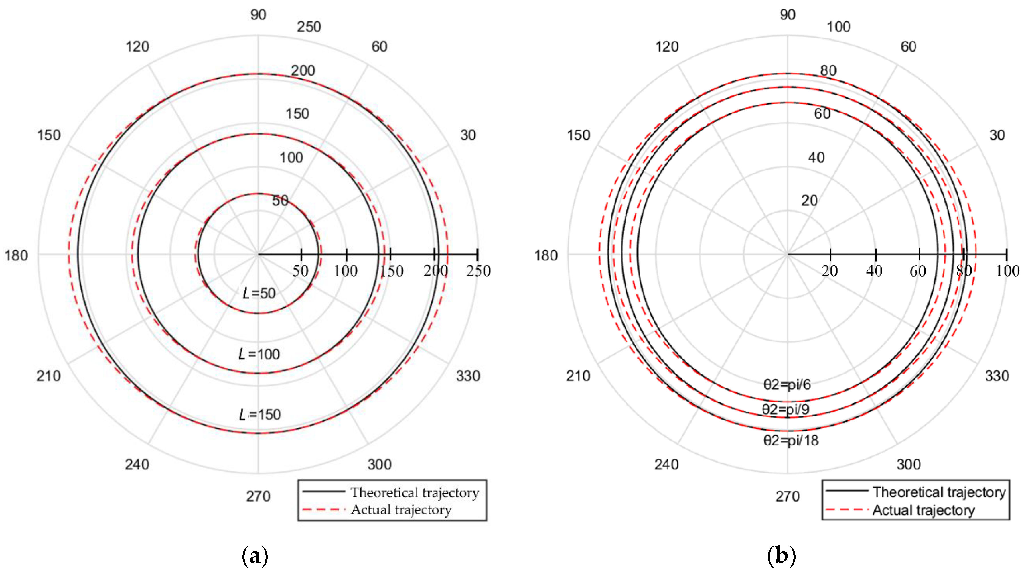
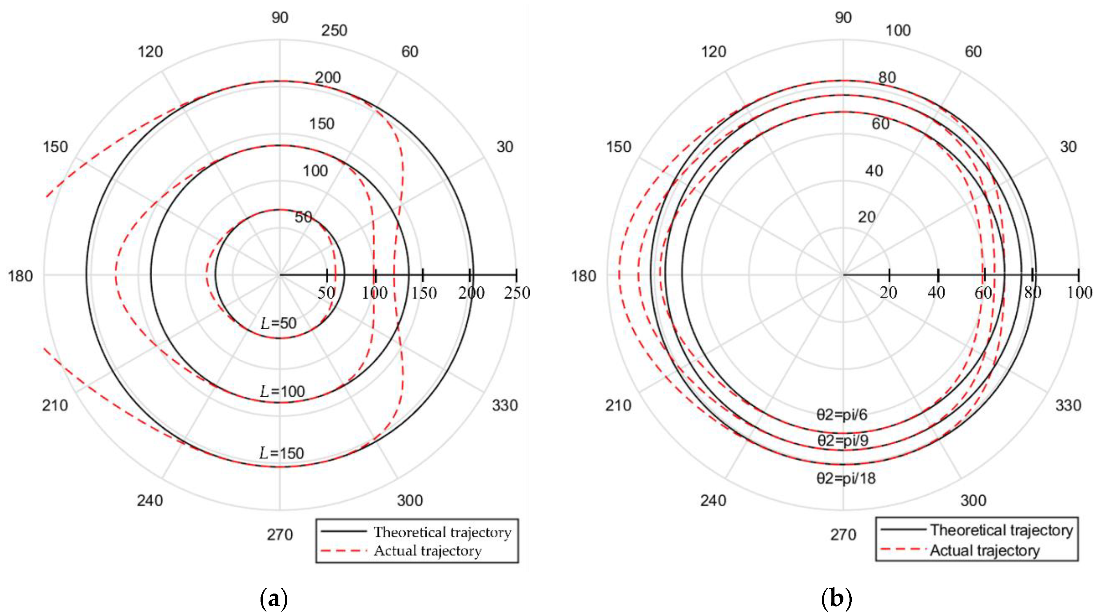
4. Simulation of the Positioning Errors

The correctness of the equation is verified efficiently by simulation analysis. To explore the trend of trajectory error, the parameters related to machine tool movement are properly set and applied in the simulation. Simulation research is mainly for vertical machine tools. In the initial parameter setting, the angles θ1 and θ2 are both π/6, and the L is 50 mm. The feed rate of the machine tool is 1000 mm/min (this parameter is set according to the no-load state of the machine tool), and the minimum moving distance is 0.001 mm. The remaining parameters are introduced in each simulation.

4.1. First-Order Contraction Error of the Ball Screw and Linear Grating

When the first-order contraction of the ball screw and linear grating exist in the machine tool, the measured radius of the machine tool in a circular motion can be written as:
R = x 0 = L cos θ 1 + L cos ( θ 1 + θ 2 )
Substituting Equation (16) into Equation (17), we can obtain:
R = 50 cos π 6 + 50 cos π 3
The design trajectory of the machine tool in a circular motion can be written as:
r = R cos θ 3 + i ( 1 + R sin θ 3 )
The real trajectory of the machine tool in circular motion is:
r 1 = R cos θ 3 + a R 2 cos 3 θ 3 + i ( 1 + R sin θ 3 )
where a = 0.1.
According to Equations (18)–(20), the first-order contraction error of the ball screw and linear grating can be obtained. The measurement radii of J-DBB vary with both the length of the bars and angles of the two bars. In the comparison diagram shown in Figure 4, the solid black lines represent the designed trajectory of the circular motion of the machine tool, and the dotted red lines represent the real trajectory of the circular motion of the machine tool. Figure 4a depicts the variations of the trajectories with different lengths of the bars. Figure 4b depicts the variations of the trajectories with the angles of the two bars. The results suggest that when the angle of the machine tool spindle is 0°and 180°, the errors are larger. On the side, the angle of the machine tool spindle is 90°and 270°, and the errors are smaller. Figure 4 shows that the equipment error increases with the increase of length L and is unchangeable with the variation of angle.

4.2. Second-Order Contraction Error of the Ball Screw and Linear Grating

When the second-order uniform contraction error of the ball screw and linear grating exists, the measured radius of the machine tool in a circular motion can be written as Equation (18). The design trajectory of the circular motion can be written as Equation (19). The real trajectory of circular motion can be written as:
r 1 = R cos θ 3 a R 2 2 cos 4 θ 3 + i ( 1 + R sin θ 3 )
where a = 0.002.
According to Equations (18), (19) and (21), the second-order contraction error of the ball screw and liner grating can be determined. In the comparison diagram shown in Figure 5, the solid black lines represent the design trajectory of the circular motion of the machine tool spindle, and the dotted red lines represent the real trajectory of the circular motion of the machine tool spindle. We can see that the real trajectory is less than the design one near 0°and the real trajectory is more than the design one near 180° for different L and θ2. Figure 5a shows that the equipment error increases with the increase of length L, and Figure 5b shows that the equipment error is unchangeable with the variation of angle.

4.3. Periodic Error of the Ball Screw and Linear Grating

When periodic errors of the ball screw and linear grating exists, the measured radius of the machine tool in a circular motion can be written as Equation (18). The design trajectory of circular motion can be written as Equation (19). The real trajectory of the circular motion can be written as:
r 1 = R cos θ 3 + d cos 2 θ 3 sin ( 2 π R cos θ 3 p φ ) + i ( 1 + R sin θ 3 )
where d = 8, P = 1, and φ = 0.
According to Equations (18), (19) and (22), the periodic error of the ball screw and linear grating can be procured. In the comparison diagram shown in Figure 6, the solid black lines represent the design trajectory of the circular motion of the machine tool spindle, and the dotted red lines represent the real trajectory of the circular motion of the machine tool spindle. Figure 6a illustrates the variation of the real trajectory of the machine tool with the different lengths of the bars. Figure 6b illustrates the variation of the real trajectory of the machine tool with the angle of the bars. We know that the real trajectory is consistent with the design one near 90°and 270°. In addition, the real trajectory has a larger amplitude near 0°and 180°for different L and θ2.

4.4. Noise of Measurement Device

When the noise of the detection device of the machine tool exists, the measured radius of the machine tool in a circular motion can be written as Equation (18). The design trajectory of the circular motion can be written as Equation (19). The real trajectory of the circular motion can be written as:
r 1 = F 2 sin 2 θ 3 cos θ 3 [ b y F cos θ 3 sin ( 2 π R cos θ 3 p φ y ) b x F sin θ 3 sin ( 2 π R cos θ 3 p φ x ) ] + R cos θ 3 + i ( 1 + R sin θ 3 )
where F = 10, bx = 1.1, by = 1.2, P = 8, φx = φy = 0.
According to Equation (18), (19) and (23), the noise of the measurement device can be procured. In the comparison diagram shown in Figure 7, the solid black lines represent the design trajectory of the circular motion of the machine tool spindle. The dotted red lines represent the real trajectory of the circular motion of the machine tool spindle. Figure 7a illustrates the influence of the noise of the measurement device on the circular motion trajectory for the J-DBB with different lengths of the bars. Figure 7b illustrates the influence of the noise of the measurement device on the circular motion trajectory o for the J-DBB with different angles of the bars. The error amplitude varies with the angles of the spindle that can be found. Generally, the error amplitude is larger near 45°, 135°, 225°, and 315°, while the error amplitude is smaller near 0°, 90°, 180°, and 270°.

4.5. Opposite Clearance

When the opposite clearance of the machine tool exists, the measured radius of the machine tool in a circular motion can be written as Equation (18). The design trajectory of the circular motion can be written as Equation (19). The real trajectory of the circular motion can be written as:
r 1 = ± f 2 cos 2 θ 3 + R cos θ 3 + i ( 1 + R sin θ 3 )
where f = 10.
According to Equations (18), (19) and (24), the opposite clearance error of the ball screw and linear grating can be procured. In the comparison diagram shown in Figure 8, the solid black lines represent the design trajectory of the circular motion of the machine tool spindle, and the dotted red lines represent the real trajectory of the circular motion of the machine tool spindle. Figure 8a illustrates the influence of the opposite clearance on the circular motion trajectory of machine tools for the J-DBB with different lengths of bars. Figure 8b illustrates the influence of the opposite clearance on the circular motion trajectory of the machine tool for the J-DBB with different angles of bars. We know that the errors vary with the angles of the spindle. When the angle is 0°, the errors are negative. With the increase of the angle, the errors are reduced. When the angle is 90°, the errors are close to 0. When the angle continues to increase, the errors keep growing. The errors reach the maximum at 180°. The errors with the angle from 180° to 360°are symmetrical and similar to the angles from 0° to 90°. Figure 8a shows that the equipment error increases with the increase of length L, and Figure 8b shows that the equipment error is unchangeable with the variation of angle.

5. Discussions

This paper study the positioning errors measurement of machine tool at the whole area used by the J-DBB method. The feasibility of the J-DBB method is theoretically verified. The J-DBB synthesized the structural characteristics of traditional DBB and two-bar linkage DBB. The spherical joint with three degrees of freedom in space is the key innovation for the J-DBB method. The free measurement of machine tool error in space is also called the full-scale measurement of machine tools [23]. By adding a spherical joint, the flexibility and measurement range of the DBB are greatly improved. The positioning errors of the machine tool can be calculated from data measured with the free radius. The discontinuous measurement with a constant radius is extended to the continuous measurement with an arbitrary radius. The radius is determined by the angle of the bars, as shown in Figure 4b, Figure 5b, Figure 6b, Figure 7b and Figure 8b. The simulation research is based on a vertical machine tool; when it executes circular motion, it is affected by the error of the positioning mechanism to simulate and analyze. The simulation results based on the J-DBB method show that the equipment error increases with the increase of length L and remains unchangeable with the variation of angle. The J-DBB method also has another significant advantage: it allows to detect errors of machine tool drive unit. These errors are caused by defects in control commands or incorrect operating procedures. Its manifestation is like machine tool positioning error, so this method can be used to analyze it.
It is noted that we studied only four kinds of positioning errors of the machine tool used by the J-DBB method. For other positioning errors in real operation, we can adopt a similar method to measure. Firstly, we analyze these errors and translate these errors into positioning errors or pendulum errors. The pendulum errors can also be transformed into positioning errors. Then, we add the positioning errors of each axis and obtain the error vectors. The positive and negative relationship of the error vectors should be seriously considered. Finally, we substitute the error vector and obtain the error equations of the CNC machine tool.
The simulated trajectory by the J-DBB method is like that by the DBB method. It shows that J-DBB-based machine tool error measurement is feasible. Some preliminary exploration of the positioning error measurement of the machine tool has been carried out in this paper. In addition, the device used in this paper verifies the measurement principle of the J-DBB method. Unfortunately, the accuracy of the MDF decoupling spatial angle is limited, so that J-DBB cannot be directly used to measure machine tool errors. In future research, it is necessary to design a more accurate spatial angle measurement device to replace the MDF so that the J-DBB device can be effectively applied to real measurement.

6. Conclusions

This paper proposes a J-DBB method that combines the structural characteristics of traditional DBB and two-bar linkage DBB. The three-degree-of-freedom spherical joint is a key innovation of the J-DBB method, which greatly improves the flexibility and measurement range of the J-DBB. J-DBB can be measured freely in the spherical space with the maximum bar length as the radius.
This paper simulated and analyzed four positioning errors of the machine tool based on the J-DBB method, including the uniform contraction error of ball screw and linear grating, periodic error of the ball screw and linear grating, interference of measurement devices error, and opposite clearance error. The influence of the length and angle of the two connecting bars on the positioning errors is studied. The simulation results based on the J-DBB method show that the equipment error increases with the increase of length L and remains unchangeable with the variation of angle.
The J-DBB realizes the whole area measurement of machine tool error by measuring the angle of the spherical joint, which helps to better explore the spatial distribution of CNC machine tool error and clarify the error of the local area of the machine tool.

Author Contributions

Conceptualization, W.W. and Y.Z.; methodology, T.S. and Y.Z.; validation, K.X. and H.W.; writing—original draft preparation, T.S., Z.C. and Z.S.; writing—review and editing, T.S., W.W., K.L. and H.Y.; supervision, W.W. All authors have read and agreed to the published version of the manuscript.

Funding

This research was funded by the Zhejiang Provincial Natural Science Foundation of China under Grant No. LZ16E050001 and the National Natural Science Foundation of China under Grant No. U1709206 and No.51275465.

Institutional Review Board Statement

Not applicable.

Informed Consent Statement

Not applicable.

Data Availability Statement

The data presented in this study are available on request from the corresponding author.

Acknowledgments

Not applicable.

Conflicts of Interest

The authors declare no conflict of interest.

Nomenclature

LThe distance between the spherical joint and each ball
θ1The angle between horizontal plane and bar 1
θ2The acute angle between two connecting bars
θ3 = vRtThe angle of rotation of machine tool after running at speed v for t seconds
aThe contraction ratio of the ball screw and linear grating, μm/mm
axThe contraction ratio of the ball screw and linear grating on x-axis, μm/mm
pThe screw pitch of the ball screw or the grating pitch of the linear grating
dThe amplitude
φThe phase angle
bxThe ratio of amplitude to velocity along the x-axis direction
byThe ratio of amplitude to velocity along the y-axis direction
φxThe phase angle along the x-axis direction
φyThe phase angle along the y-axis direction
FThe velocity of machine tool spindle, m/s
fThe opposite clearance
rThe design trajectory of circular motion
r1The real trajectory of circular motion

References

  1. Ibaraki, S.; Knapp, W. Indirect measurement of volumetric accuracy for three-axis and five-axis machine tools: A review. Int. J. Autom. Technol. 2012, 6, 110–124. [Google Scholar] [CrossRef] [Green Version]
  2. Mekid, S.; Ogedengbe, T. A review of machine tool accuracy enhancement through error compensation in serial and parallel kinematic machines. Int. J. Precis. Technol. 2010, 1, 251–286. [Google Scholar] [CrossRef]
  3. Huo, F.; Poo, A. Nonlinear autoregressive network with exogenous inputs based contour error reduction in CNC machines. Int. J. Mach. Tools Manuf. 2013, 67, 45–52. [Google Scholar] [CrossRef]
  4. Jiang, X.P.; Cripps, R. A method of testing position independent geometric errors in rotary axes of a five-axis machine tool using a double ball bar. Int. J. Mach. Tools Manuf. 2015, 89, 151–158. [Google Scholar] [CrossRef] [Green Version]
  5. Ramesh, R.; Mannan, M.A.; Poo, A.N. Error compensation in machine tools—Review: Part I: Geometric, cutting-force induced and fixture-dependent errors. Int. J. Mach. Tools Manuf. 2000, 40, 1235–1256. [Google Scholar] [CrossRef]
  6. Bryan, J.B. A simple method for testing measuring machines and machine tools, part 1: Principles and application. Precis. Eng. 1982, 4, 61–69. [Google Scholar] [CrossRef]
  7. Bryan, J.B. A simple method for testing measuring machines and machine tools, part 2: Construction. Precis. Eng. 1982, 4, 125–138. [Google Scholar] [CrossRef]
  8. Srivastava, A.K.; Veldhuis, S.C. Modelling geometric and thermal errors in a five-axis CNC machine tool. Int. J. Mach. Tools Manuf. 1995, 35, 1321–1337. [Google Scholar] [CrossRef]
  9. Yang, S.H.; Kim, K.H.; Park, Y.K.; Lee, S.G. Error analysis and compensation for the volumetric errors of a vertical machining centre using a hemispherical helix ball bar test. Int. J. Adv. Manuf. Technol. 2004, 23, 495–500. [Google Scholar] [CrossRef]
  10. Lei, W.T.; Sung, M.P.; Liu, W.L.; Chuang, Y.C. Double-ball-bar test for the rotary axes of five-axis CNC machine tools. Int. J. Mach. Tools Manuf. 2007, 47, 273–285. [Google Scholar] [CrossRef]
  11. Lei, W.T.; Hsu, Y.Y. Error measurement of five-axis CNC machine with 3D probe-ball. J. Mater. Process. Technol. 2003, 139, 127–133. [Google Scholar] [CrossRef]
  12. Lee, K.I.; Yang, S.H. Accuracy evaluation of machine tools by modeling spherical deviation based on double ball-bar measurements. Int. J. Mach. Tools Manuf. 2013, 75, 46–54. [Google Scholar] [CrossRef]
  13. Lee, K.I.; Yang, S.H. Measurement and verification of position-independent geometric errors of a five-axis machine tool using a double ball-bar. Int. J. Mach. Tools Manuf. 2013, 70, 45–52. [Google Scholar] [CrossRef]
  14. Florussen, G.H.J.; Delbressine, F.L.M.; Schellekens, P.H.J. Assessing thermally induced errors of machine tools by 3D length measurements. Int. J. Mach. Tools Manuf. 2003, 27, 105–109. [Google Scholar] [CrossRef]
  15. Yukio, T.; Gang, S.; Hiroaki, F. A DBB-based kinematic calibration method for in-parallel actuated mechanisms using a fourier series. J. Mech. Des. 2004, 12, 846–857. [Google Scholar]
  16. Heui, J.P.; Young, S.K. A new technique for volumetric error assessment of CNC machine tools incorporating ball bar measurement and 3D volumetric error model. J. Mech. Des. 1997, 37, 1583–1596. [Google Scholar]
  17. Kakino, Y.; Ihara, Y.; Nakatsu, Y.; Okamura, K. The measurement of motion errors of NC machine tools and diagnosis of their origins by using telescoping magnetic ball bar method. CIRP Ann.-Manuf. Technol. 1987, 36, 377–380. [Google Scholar] [CrossRef]
  18. Iwai, H.; Mitsui, K. Development of a measuring method for motion accuracy of NC machine tools using links and rotary encoders. Int. J. Mach. Tools Manuf. 2009, 49, 99–108. [Google Scholar] [CrossRef]
  19. Furutani, R.; Kamahora, K. Development of a new artifact for the calibration of large scale instruments. Measurement 2001, 30, 139–143. [Google Scholar] [CrossRef]
  20. Qiu, H.; Li, Y.; Li, Y. A new method and device for motion accuracy measurement of NC machine tools. Part 1: Principle and equipment. Int. J. Mach. Tools Manuf. 2001, 41, 521–534. [Google Scholar] [CrossRef]
  21. Qiu, H.; Li, Y.; Li, Y. A new method and device for motion accuracy measurement of NC machine tools. Part 2: Device error identification and trajectory measurement of general planar motions. Int. J. Mach. Tools Manuf. 2001, 41, 535–554. [Google Scholar] [CrossRef]
  22. Kono, D.; Sakamoto, F.; Iwao, Y. Linked ball bar for flexible motion error measurement for machine tools. Int. J. Autom. Technol. 2017, 11, 188–196. [Google Scholar] [CrossRef]
  23. Wang, W.; Chen, Z.F.; Zhu, Y.W.; He, Y.; Lu, K.; Shi, G.; Kui, X.; Ju, B. Full-scale measurement of CNC machine tools. Int. J. Adv. Manuf. Technol. 2020, 107, 2291–2301. [Google Scholar] [CrossRef]
  24. Shi, S.; Lin, J.; Wang, X.; Xu, X. Analysis of the transient backlash error in CNC machine tools with closed loops. Int. J. Mach. Tools Manuf. 2015, 93, 49–60. [Google Scholar] [CrossRef]
  25. Yadav, A.K.; Gaur, P. Modified IMC technique for nonlinear uncertain milling CNC machine tool system. Arab. J. Sci. Eng. 2020, 45, 2065–2080. [Google Scholar] [CrossRef]
  26. Yang, J.; Altintas, Y. A generalized on-line estimation and control of five-axis contouring errors of CNC machine tools. Int. J. Mach. Tools Manuf. 2015, 88, 9–23. [Google Scholar] [CrossRef]
  27. Du, Z.; Zhang, S.; Hong, M. Development of a multi-step measuring method for motion accuracy of NC machine tools based on cross grid encoder. Int. J. Mach. Tools Manuf. 2010, 50, 270–280. [Google Scholar] [CrossRef]
  28. Ibaraki, S.; Iritani, T.; Matsushita, T. Calibration of location errors of rotary axes on five-axis machine tools by on-the-machine measurement using a touch-trigger probe. Int. J. Mach. Tools Manuf. 2012, 58, 44–53. [Google Scholar] [CrossRef] [Green Version]
  29. Lee, D.M.; Zhu, Z.; Lee, K.I.; Yang, S.H. Identification and measurement of geometric errors for a five-axis machine tool with a tilting head using a double ball-bar. Int. J. Precis. Eng. Manuf. 2011, 12, 337–343. [Google Scholar] [CrossRef]
  30. Xiang, S.; Yang, J.; Zhang, Y. Using a double ball bar to identify position-independent geometric errors on the rotary axes of five-axis machine tools. Int. J. Adv. Manuf. Technol. 2014, 70, 2071–2082. [Google Scholar] [CrossRef]
Figure 1. Structure of the J-DBB.
Applsci 11 11770 g001
Figure 2. The angle measuring device of the spherical joint. (a) The angle measuring device. (b) The structure of spherical joint.
Applsci 11 11770 g002
Figure 3. Measuring coordinates of the J-DBB.
Applsci 11 11770 g003
Figure 4. Simulation results of the influence of the first order uniform contraction of ball screw and linear grating on the circular motion trajectory of machine tool. (a) The result under different bar lengths. (b) The result under different pose angles.
Applsci 11 11770 g004
Figure 5. Simulation results of the influence of the second order uniform contraction of ball screw and linear grating on the circular motion trajectory of machine tool. (a) The result under different bar lengths. (b) The result under different pose angles.
Applsci 11 11770 g005
Figure 6. Simulation results of the influence of the periodic errors on the circular motion trajectory of machine tool. (a) The result under different bar lengths. (b) The result under different pose angles.
Applsci 11 11770 g006
Figure 7. Simulation results of the influence of the noise of measurement device on the circular motion trajectory of machine tool. (a) The result under different bar lengths. (b) The result under different pose angles.
Applsci 11 11770 g007
Figure 8. Simulation results of the influence of the opposite clearance on the circular motion trajectory of machine tool. (a) The result under different bar lengths. (b) The result under different pose angles.
Applsci 11 11770 g008
Table 1. The positioning errors of CNC machine tool.
Num.Error Types
1Uniform contraction error of ball screw and linear grating
2Periodic error of the ball screw and linear grating
3Interference of measurement devices
4Opposite clearance
Publisher’s Note: MDPI stays neutral with regard to jurisdictional claims in published maps and institutional affiliations.

