Abstract
The main purpose of the article is to describe the methodology used for multi-criteria optimization of the geometric features of the orthopedic implant used for the reconstruction of the anterior cruciate ligament located in the knee joint. The methodology includes: 1. Method of development of the bones of the knee joint model; 2. Method of multi-criteria optimization of the geometric features of the orthopedic implant using an artificial immune system, the objective function and the Pareto front; 3. Expert evaluation method based on forms. The work confirmed that the assumed thesis, a multi-criteria optimization using an artificial immune system, which is a specially defined objective function, and the Pareto method, which allows to determine the geometrical features of the implant, will lead to fulfill optimal blood perfusion and sufficient strength properties of the implant simultaneously. We conclude that the described methodology allowed to achieve the optimal geometrical features of the orthopedic implant used for reconstruction of the anterior cruciate ligament located in the knee joint.
1. Introduction
In the modern world, an interdisciplinary approach is very important when solving engineering and medical issues, resulting in significant advances in medical technologies.
The growing civilization is causing an increase of the number of injuries among citizens. In the case of athletes, it is caused by the increasing exploitation of the body, while for people leading a sedentary lifestyle, it is caused by lack of experience with sport. An increasingly frequent injury is the rupture of the Anterior Cruciate Ligament (ACL), which is located in the knee joint.
The subject of this article is the optimal selection of the design features of the new implant used during the reconstruction of the anterior cruciate ligament. Such a reconstruction consists of inserting a graft (usually autogenous, e.g., a tendon) in place of the broken anterior cruciate ligament in the knee joint. The main problem during the surgery is the proper placement of the new graft in the bones of the knee joint and ensuring adequate fluid flow of blood and other body fluids in order to “nourish” it.
The regenerative processes are responsible for the reconstruction of the bones in the body [1]. However, it is a slow process that depends on the patient’s health, age, and individual characteristics.
For the anterior cruciate ligament (ACL) reconstruction surgery to be successful, the graft inserted into the bone canals must grow in [2,3,4]. Prof. Krzysztof Ficek (the Medical Center Galen-Ortopedia in Bieruń, Poland.) proposed the use of bioresorbable orthopedic implants to increase the probability of better fixation of the graft in the bone canals [5,6]. The role of implant is to create a kind of “scaffolding” in the bone canal for the implanted graft, precisely anchoring it in the bone canal. Bioresorbable properties of the implant are expected to accelerate the bone tissue ingrowth into the graft, so that the graft is properly stabilized and can take over the role of the anterior cruciate ligament in the knee joint [7]. The implant should be strong enough and allow the best blood perfusion, so that the graft and bone tissue will be properly “nourished”, which will accelerate the growth of bone building cells into the graft.
An orthopedic implant should have appropriate geometrical features (Figure 1) and dimension system so that it fulfills its function in the best possible way [8,9].
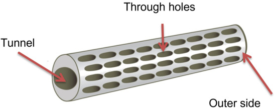
Figure 1.
Geometrical features of orthopedic implant.
While orthopedic implant must include two different criteria, it is necessary to use multi-criteria optimization. Since a satisfactory mathematical model, which comprises both the problems of proper blood flow through the implant and the implant strength in case of overloads in a knee joint has not been developed yet, then Artificial Immune Systems from heuristic algorithms class will be used for the multicriterial optimization. The goal of the multicriterial optimization is to find an optimal solution due to the given criteria.
In summary, the scientific goal of the work is to develop the methodology used for multi-criteria optimization of the geometric features of an orthopedic implant used for the reconstruction of the anterior cruciate ligament located in the knee joint. The implant should precisely fix the graft in the bone tunnel and accelerate the bone tissue ingrowth into the graft so that it can take over the role of a broken ligament.
The aim of the research is to determine the optimal geometric features of implants in terms of two criteria, which are: the best possible use of the strength properties of the implant (with the limit on allowable stresses) and optimal blood saturation of the graft.
The article describes the subject of the author’s doctoral dissertation, the Promoter of which was Prof. Wojciech Moczulski (Silesian University of Technology).
2. Materials and Methods
The methodology includes:
- 1.
- Method of developing a model of the bones of the knee joint;
- 2.
- Method of multi-criteria optimization of the geometric features of an orthopedic implant using the artificial immune system, the objective function, and the Pareto front;
- 3.
- Expert evaluation method based on forms.
2.1. Method of Developing a Model of the Bones of the Knee Joint
The method consists of creating three-dimensional models of the femur and tibia on the basis of DICOM images (Digital Imaging and Communications in Medicine) from computed tomography [10].
Computed tomography (CT) is a study that uses the absorption of X-rays in tissues and organs of the body of different density and thickness. It involves the registration of layered images from any cross-section, which allows a creation of a three-dimensional image. The results of the CT are photos of individual layers, where each pixel has a numerical value describing the radiological density, determined in Hounsfield (HU) units. In the image, these units correspond to shades in grayscale. The dependence of the Hounsfield unit on the permeation coefficient is represented by the formula:
—tissue absorption coefficient.
—water absorption coefficient.
The scale of units (HU) is 4000 degrees, from –1000 for air (dark shades in the image) to +3000 for bone (light shades), water is 0.
Specialized bioengineering software allows mapping the structure of the human organ, based on the loaded DICOM [11] images. The method of obtaining a model of the femur is shown in the Figure 2.
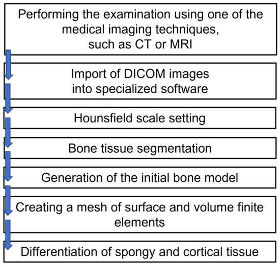
Figure 2.
The method of modeling the femur model.
Following the Figure 2, the femur and tibia were modeled with a differentiation between spongy and compact bone, which is of great importance in the strength analysis of such a system.
In the first stage, the model of the exemplary orthopedic implant was inserted into the bone model (Figure 3) and the strength analysis has been performed. The analysis has provided an answer regarding what forces and stresses act in such an implant during the load on a 50th-centile patient’s knee joint.
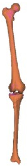
Figure 3.
Models of the femur and tibia.
In the second stage, the implant selected in the optimization process was implemented into the bone to observe what happens in the implant during the loading of the leg after reconstruction of the anterior cruciate ligament in the knee.
The Table 1 shows the selected mechanical properties of the cortical and spongy bone.

Table 1.
Mechanical properties of the bone tissue of the femur.
2.2. The Method of Multi-Criteria Optimization of the Geometric Features of an Orthopedic Implant with the Use of Artificial Immune System, the Objective Function, and the Pareto Front
Among many heuristic algorithms, e.g., genetic algorithms, immune algorithms, neural networks, swarming algorithms, and ant algorithms, were selected as the immune algorithms [12,13,14,15,16,17]. Literature research shows that these algorithms should be the fastest way to solve a problem with many conflicting criteria [12,14,17].
Artificial Immune System (AIS) is based on the principle of operation of the biological immune systems of living organisms. Their main advantages are the skills:
- Learning;
- Remembering (and forgetting);
- Maintaining population diversity;
- Adapting to new situations.
Optimal individuals are found with the help of the target function and the Pareto front. When using the target function, the best individual is selected (as a weighted sum of components determined for the strength and fluid flow criteria). On the other hand, the Pareto front is determined by dominated and non-dominated (Pareto-optimal) individuals, and then the best solution is selected from them. Finally, the methods were compared. The optimization process has been implemented in the MATLAB® environment.
2.2.1. The Method of Multi-Criteria Optimization with the Use of an Immune Algorithm
The clonal selection algorithm was selected from immune systems methods. A general algorithm of the immune system is shown in Figure 4.
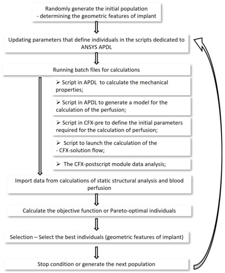
Figure 4.
General algorithm of the immune system used.
The optimization process has been implemented in the MATLAB® environment. The ANSYS APDL software was used for strength calculations, the ANSYS CFX software was used for fluid flow calculations. Each software has been prepared for fully automatic calculations. running a Matlab program, automatically running batch files for strength and fluid flow calculations, which automatically returned the results to the main function, where the immune algorithm has been continued.
Implant Concepts
The optimization process has changed the size and arrangement of the through holes (Figure 5), which regulated the rate of blood perfusion. The segment of a hollow tapered cylinder has been selected in the earlier research. When oozing blood through the implant, the described shape ensures an adequate blood supply to the transplant, with the least possible rinsing of the bone-forming cells already embedded in the graft and implant.
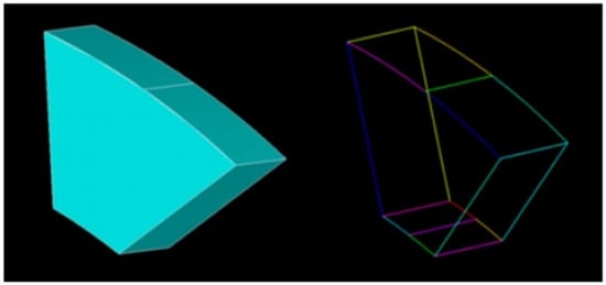
Figure 5.
Through holes in implant concepts.
The dimensions of the implant are closely related to the humans anatomical characteristic and the surgical instruments. Ultimately, a typology of geometric forms of orthopedic implants should be made, differing in the external and internal diameter of the implant and its length.
In the described work, specific size of an orthopedic implant has been selected (after consultation with a doctor):
- External diameter—11 mm;
- Internal diameter—9 mm;
- Length—40 mm.
The material that has been selected for this work is LATI Latigea B01 F1 Bio-Polymer [18].
The through-holes on the implant surface have been described by parameters that are closed in the following compartments (Figure 6):
- D—The length of the through hole along the axis on the implant surface z—D ∈ [0.5, 3] mm;
- B—Through-hole width—B ∈ [1, 1.7] mm;
- —Distance between holes— ∈ [0.1, 10] mm;
- —The angle by which the through holes in the next row are offset from the previous row— ∈ [0, 30].
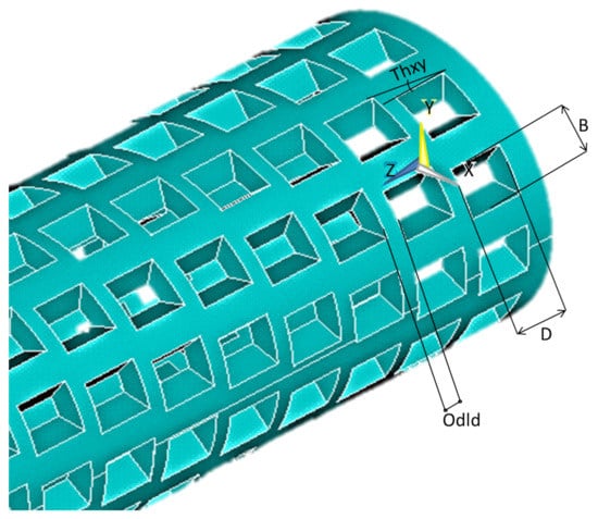
Figure 6.
Designation of parameters controlling the form and dimensions of through holes.
These ranges have been defined to maintain the feasibility of the geometrical features of the implant and the desired strength properties.
The immunological algorithm generates each individual, specifying its characteristics from the interval describing the holes on the implant surface. An exemplary individual is saved with four items Figure 7.

Figure 7.
An exemplary individual is saved with four items.
Each individual generated by the immunological algorithm is a separate set of geometrical features of the implant, the parameters of which must be transferred to the script written in APDL and the stresses occurring in it must be calculated for each individual. That is why it was so important to parameterize and automate the calculation process of strength properties.
Module that calculates the stresses in the implant
In the script for the Mechanical APDL environment for strength calculations, the following was specified:
- The process of generating geometrical features of orthopedic implants, as shown in Figure 8;
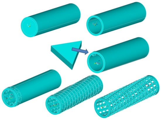 Figure 8. The process of generating geometrical features of orthopedic implants.
 - Determining the type and size of finite elements—SOLID187—1 mm (a solid element, 10-node, with 3 degrees of freedom, with translations in the direction of x, y, z, with a side length of 1 mm [19]). The size and type of the mesh have been selected prior to the optimization process and are not optimized with each new individual. FEM was selected with regard to the acceptable stress results and the simulation time Figure 9;
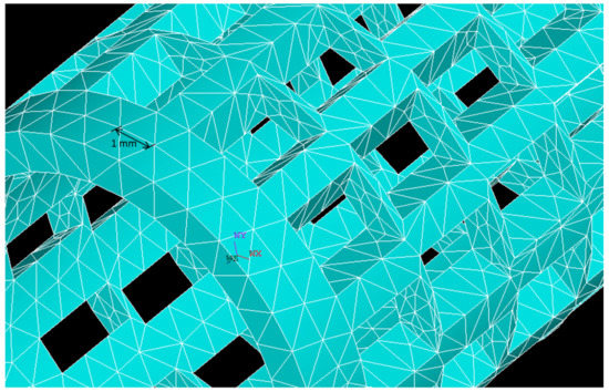 Figure 9. Defining a finite element mesh.
 - Assignment of material properties;
- Automatic extraction of a restraint plane, receiving degrees of freedom of one of the planes (Figure 10);
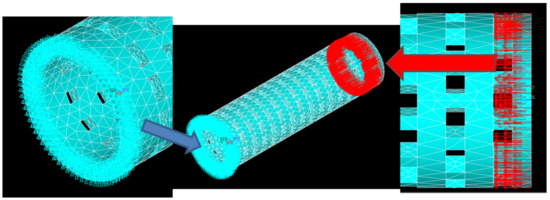 Figure 10. Fixation and force application definition.
 - Automatic extraction of a plane to which an external force of 10 N has been applied (Figure 10);
- Calculation of implant stresses;
- Save results as text and model.
Fluid flow calculating module
For blood perfusion calculations, in the Mechanical APDL language, a negative of the implant body has been made, which is a model of the volume of fluid flowing through the implant (Figure 11).
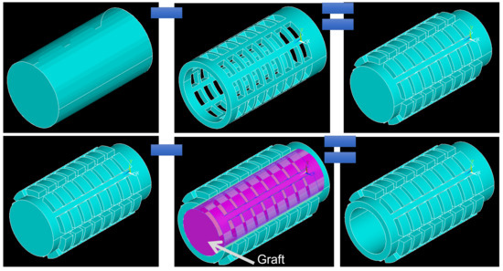
Figure 11.
Preparation of the model of the fluid volume in the implant.
The ANSYS CFX module is divided into three sections:
- CFX-Pre—define initial values (Figure 12);
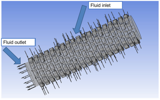 Figure 12. Determination of fluid inlet and outlet.
 - CFX-Solution—fluid flow calculation;
- CFX-Post—visualization and generation of fluid flow calculation results.
A separate script has been written for each section in a special CFX Command Language (CCL), automatically called in the MATLAB environment through batch files.
Criteria of Concept Evaluation—Strength
Strength properties have been calculated in ANSYS Mechanical APDL software (ANSYS Parametric Design Language). To get the most out of the material, a dependency was used
Since the value searched for is the minimum of the function, this relationship allows us to get closer to the optimal use of the material.
This also added dependency: If for a given individual the calculated stresses exceed stresses that are allowed, it is immediately removed and does not participate in further simulation.
Criteria of Concept Evaluation—Blood Flow
During the blood perfusion test, after analyzing many parameters such as fluid flow velocity, molecular weight or pressure at the exit of the implant tunnel, it has been decided to test the fluid pressure at the exit of the tunnel.
If the calculated pressure is less than the specified fluid pressure then:
Otherwise:
Such a dependency, during the optimization process, makes it possible to find an implant with a fluid flow pressure value close to the previously determined blood flow pressure value.
Objective Function
Objective functions have been defined.
If the calculated pressure is less than the required pressure, then:
Otherwise:
Pareto Method
For each individual, the coefficient of using the stress properties is calculated according to Formula (1) and blood perfusion—Formulas (2) or (3). Then, these values have been checked according to Formula (6).
2.3. Expert Evaluation Method Based on Forms
The expert evaluation method consists of developing and conducting surveys enabling the assessment of models of orthopedic implants among specialist engineers, who evaluate their opinion according to the possibility of producing implants and among doctors, who evaluate the product in terms of medicine. The specialists evaluating a given questionnaire formulates their assessment using the quantitative scale (only in two exceptions is the answer yes/no, classifying a given individual). This scale is included in the set 1–3 and consists of classifying individuals from the best to the worst among the presented solutions [20,21,22].
3. Results
The results of the two methods used in the study are presented and compared below. Additionally, the strength verification was made.
3.1. Simulation Results Using the Objective Function
Weights for both criteria equal 0.5.
The algorithm made it possible to find the result after 24 main iterations and ended the calculations due to the lack of significant improvement in the results in subsequent iterations. The diagram below (Figure 13) shows the direction of the optimization process in subsequent iterations.
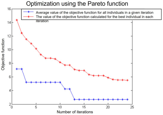
Figure 13.
Optimization using the Pareto function.
The red graph shows the mean value of the objective function computed for all individuals in each iteration, while the blue plot shows the value of the objective function computed for the best individual in each iteration.
The red graph shows no improvement in the averaged results in the last iterations, so the program has been discontinued. However, the optimal individual was found already in the 13th iteration.
The result obtained thanks to the use of immune algorithms is shown on Figure 14. This implant is characterized by densely spaced holes in the following rows.
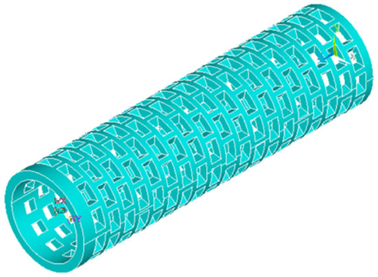
Figure 14.
Optimal geometrical characteristics of the implant selected by the immune algorithm using the objective function.
3.2. Simulation Results Using the Pareto Method
The immune algorithm using the Pareto function completed the calculations after 100 iterations (the algorithm was stopped after reaching the set number of iterations). The Pareto function returned 185 results, including 7 non-dominated individuals forming the Pareto front. On Figure 15, the dominant individuals are marked blue, while the Pareto front is marked red.
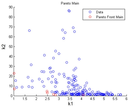
Figure 15.
Pareto-optimal individuals with Pareto front; k1—calculated value of the strength properties criterion; k2—calculated value of the blood perfusion criterion.
The figure shows the geometrical features (Figure 16).
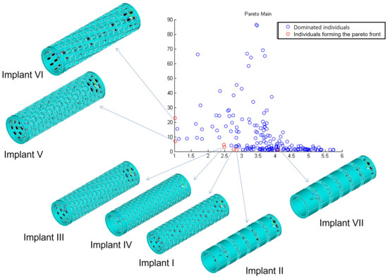
Figure 16.
Geometric features of Pareto-optimal individuals.
Analyzing the results above, implant No. III (Figure 16) was chosen as the best solution, because it combines the best strength properties and the best blood perfusion properties at the same time.
3.3. Comparison of Both the Methods
Both the methods described above allowed to obtain very similar optimization results.
A comparison below illustrates (Figure 17) the best individual selected by the target function (FC individual) and the best individual selected from the Pareto front (FPIII individual).
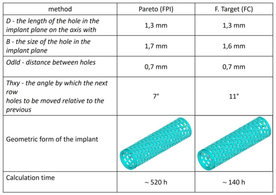
Figure 17.
Comparison of geometric features obtained with both methods for the FPI and FC implants.
In addition, among the individuals included in the Pareto front, another individual was found, which is geometrically similar to the individual found by the target function. This individual is Implant No. I (FPI subject).
3.4. Strength Verification
Strength has been verified by checking whether a specific implant will not be damaged during its implantation and normal functioning of the patient after the reconstruction of the anterior cruciate ligament.
Verification of the implantation process
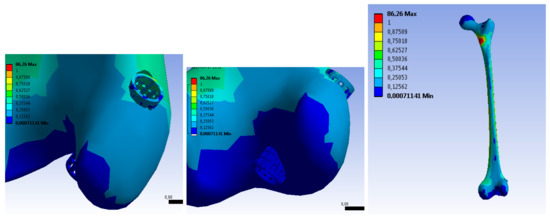
One of the most critical moments during the surgery is the moment when the graft is installed through the bone tunnel in the tibia and femur. An additional advantage of using implants is the protection of the graft during its implantation. In order to be able to estimate the value of the force required to install the graft, Prof. M. Wyleżoł developed a special device for measuring force, using a linear force meter of the FB series with a digital analyzer by AXIS [23]. The maximum force that was recorded was 400 N, and this was also the force used in the strength analysis of the implant.
During the simulation (in the ANSYS Workbench program), the force was applied (Figure 18) to the inner walls of the implant tunnel, towards the exit from the tunnel (oriented facing upwards, along the axis of the implant, which is the red area), while the implant has been fixed on its outer surface and on one of the walls of the tunnel exit (blue area). To avoid the maximum stresses accumulated at the edges of the surface, all edges were rounded.
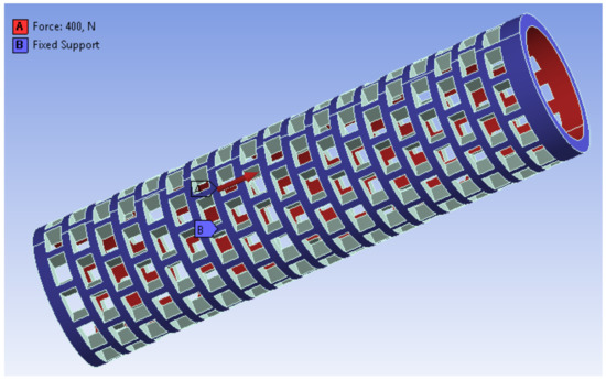
Figure 18.
Applied force and implant fixation.
The simulation results are presented in the following figures:
- Figure 19—stress results. A maximum stress of 1.66 MPa has been observed at the edge of one of the holes on the implant surface;
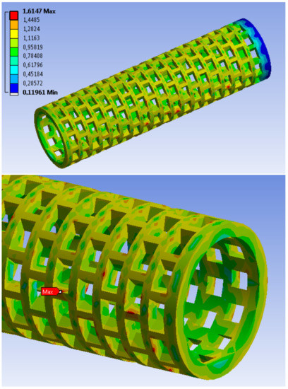 Figure 19. Stress distribution in the implant.
 - Figure 20—results of implant deformation. The maximum deformation (equal to 8.8 × 10 mm) can also be observed at the edge of one of the holes at the bottom of the implant, oriented to the knee direction.
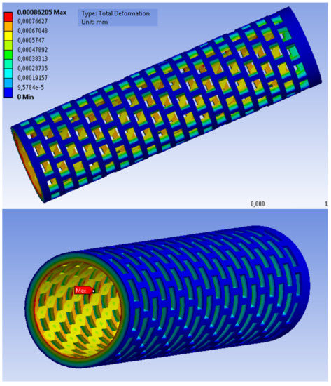 Figure 20. Distribution of deformation in the implant.
The conducted tests showed the weakest areas of the implant. They turned out to be areas around the holes on the implant surface. Despite these areas, the test implant should withstand the process of dragging the graft through it while it is anchored in the bone.
Verification of the strength of the implant in the bone
The implant obtained during optimization using the objective function was inserted into the bone model at the appropriate angle (this angle was measured on DICOM images (from MRI) of patients after anterior cruciate ligament reconstruction).
The Pauwelsa [24] model has been used to determine the load on the femur (the calculations have been based on the model of a two-arm lever realizing the loads on the femoral head while standing on one leg).
The calculated forces have been plotted on a bone model (Figure 21). A force R (211,043 N) was applied at an angle of 25° to the head of the cortical bone. A force F (155,524 N) was applied at an angle of 35° to the epiphysis of the femoral head.
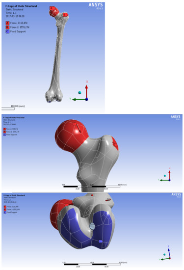
Figure 21.
Define a restraint site and apply forces to the femur.
The results of the strength simulation showed that most of the load is transferred by hard tissue, therefore the loads transmitted to the soft tissue and the implant have not been significant.
Selected simulation results have been presented in the figures below:
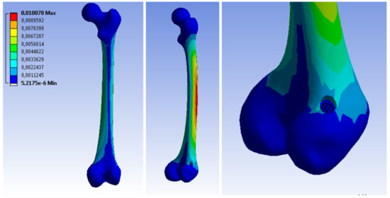
By analyzing the obtained results, it has been found that the implant would not be damaged at the first phase of the patient’s convalescence during the permitted activities.
Both the stages of the strength simulation confirmed that the implant will not be damaged.
4. Discussion
The above examples illustrate that despite the emergence of different sets of geometric features by immune algorithms, these implants are very similar to each other. This means that the best implant can be selected from the specific individuals in terms of the following criteria, such as:
- Method of production;
- Geometric form mold;
- Mold production;
- Price preparation of the implant;
- Implant manufacturing time;
- Product price;
- Method of sterilization;
- How the implant is implemented during surgery.
Examples of such criteria could be multiplied, but this is not the purpose of this work.
When comparing the obtained implants, pay attention to the simulation calculation time.
The method using the objective function is much faster.
The main advantage of this algorithm is the fact that a satisfactory result is found much faster, which is associated with the analysis of a lot smaller number of individuals. However, it must be remembered that the choice of weights in Formulas (4) and (5) is often subjective. The algorithm using the Pareto fronts has a significantly longer computation time since in each iteration there may be several or even a dozen non-dominated individuals, which multiplies the number of subsequent operations, such as cloning, which causes the number of individuals to constantly increase. Testing more individuals may have benefits such as reducing the risk of getting stuck in the local optimum and increasing the chance of approaching the global optimum.
Pareto-optimal solutions are those for which there is no other solution to improve the value for one criterion, without deteriorating the value of another criterion. The most common Pareto-optimal solutions are multiplied, creating the so-called Pareto, so at the end there is the problem of choosing one best solution [25,26].
Of the many heuristic methods, the immunological algorithms [13,16] were selected. Literature research shows that these algorithms should the fastest converge to the solution with many contradictory criteria [12,14,17].For multi-criteria optimization, Artificial immune systems were also used by de Castro and Zuben and Gong et al. [27,28].
By analyzing the examples above, satisfactory results were obtained in terms of the criteria selected by the authors. However, these results should be verified in terms of manufacturing method and cost and be consulted with surgeons and orthopedic doctors. For this purpose, two questionnaires were created, addressing to two groups of specialists—engineers and doctors.
The specialist assessing a given questionnaire formulates their assessment, primarily using the quantitative scale (only in two exceptions is the answer yes/no, classifying a given individual). This scale is included in the set 1–3 and consists of classifying individuals from the best to worst among the presented solutions [20,21,22].
The same three subjects were compared in both questionnaires. The first implant is an individual selected from the Pareto front, referred to as the IV implant (Figure 16.). The second implant also comes from the Pareto frontal algorithm, but it is an individual from the pool of dominated individuals.
The best individual selected by the target’s functions was selected as the last implant.
Engineers chose implant 2 as the best in terms of production, but it can be assumed that the differences between the presented models are small.
On the other hand, in the group of doctors, model 2, i.e., an individual dominated in the Pareto function, was rated as the worst one. In the subjective opinion of doctors, the best geometric form was captured on implant No. 3, i.e., a model obtained from multi-criteria optimization using the objective function.
In addition, in the comments in the questionnaire, it has been added that the appropriate balance between the growth of new bone tissue and the resorption of the implant would not be maintained in implant No. 2, which disqualifies it. This conclusion confirmed the proper optimization direction, as this solution was also rejected by the algorithms used.
5. Conclusions
The presented research confirms that the multi-criteria optimization using an artificial immune system, a specially defined objective function and the Pareto method allows to determine the geometrical features of the implant, which lead to fulfill optimal blood perfusion and sufficient strength properties of the implant simultaneously.
The above studies lead to the following conclusions:
- 1.
- The methodology of multi-criteria optimization of geometric features was developed with the construction of a fully automatic environment for its implementation;
- 2.
- The multi-criteria optimization process was successful and the optimal (according to the given criteria) geometric features of an orthopedic implant for the reconstruction of the anterior cruciate ligament in the knee joint were selected;
- 3.
- The implementation of the multi-criteria optimization algorithm in the MATLAB® environment significantly simplified the optimization process;
- 4.
- The use of batch files for strength calculations and blood perfusion allowed to automate the optimization process;
- 5.
- The use of the Pareto method allows for a greater selection of Pareto-optimal solutions that can be applied, but it did not produce a better result, despite searching a much larger number of solutions;
- 6.
- Optimization using the objective function allows to obtain comparable results with optimization using the Pareto method, however, the computation time in the first case is much shorter;
- 7.
- A very important step in optimization is the appropriate selection of criteria and assigning them weights;
- 8.
- Verification of the geometrical characteristics of the implant after implementation in the femur model confirmed the possibility of using such a solution;
- 9.
- Verification of the implant model has shown that it will not be damaged during implantation.
Funding
This research received no external funding.
Institutional Review Board Statement
Not applicable.
Informed Consent Statement
Not applicable.
Data Availability Statement
Not applicable.
Acknowledgments
The authors are thankful for the support from Moczulski (Department of Fundamentals of Machinery Design, Faculty of Mechanical Engineering, Silesian University of Technology), Ficek (Galen-Ortopedics) and Wyleżoł (Department of Fundamentals of Machinery Design, Faculty of Mechanical Engineering, Silesian University of Technology).
Conflicts of Interest
The author declares no conflict of interest.
Abbreviations
The following abbreviations are used in this manuscript:
| ACL | Anterior Cruciate Ligament |
| DICOM | Digital Imaging and Communications in Medicine |
| AIS | Artificial Immune System |
| ANSYS APDL | Ansys Parametric Design Language |
| ANSYS CFX | Ansys Fluid dynamics simulation |
References
- Chandrashekar, N.; Slauterbeck, J.; Hashemi, J. Sex-based differences in the anthropometric characteristics of the anterior cruciate ligament and its relation to intercon dylar notch geometry: A cadaveric study. Am. J. Sport. Med. 2005, 33, 1492–1498. [Google Scholar] [CrossRef] [PubMed]
- Ficek, K.; Rajca, J.; Stolarz, M.; Stodolak-Zych, E.; Wieczorek, J.; Muzalewska, M.; Wyleżoł, M.; Wróbel, Z.; Binkowski, M.; Błażewicz, S. Bioresorbable stent in anterior cruciate ligament reconstruction. Polymers 2019, 11, 1961. [Google Scholar] [CrossRef] [PubMed] [Green Version]
- Roberts, D.; Friden, T.; Zatterstrom, R.; Lindstr, A.; Moritz, U. Proprioception in people with anterior cruciate ligament-deficient knees: Comparison of symptomatic and asymptomatic patients. J. Orthop. Sport. Phys. Ther. 1999, 29, 587. [Google Scholar] [CrossRef] [PubMed] [Green Version]
- Rajca, J.; Gzik, M.; Ficek, K. The Influence of Bone Bruises on Bone Tunnel Enlargement Regarding ACL Rupture. Appl. Sci. 2021, 11, 2482. [Google Scholar] [CrossRef]
- Ficek, K. Implant Medyczny do Wzmacniania Wgajania Przeszczepów w Rekonstrukcji więZadeł w Tunelach Kostnych. Patent PL217967 B1, 2014. [Google Scholar]
- Stodolak-Zych, E.; Ficek, K.; Wieczorek, J.; Kajor, M.; Gryń, K.; Rapacz-Kmita, A.; Rajca, J.; Kosenyuk, Y.; Stolarz, M.; Blazewicz, S. Assessment of sheep knee joint after ACL replacement with Achilles tendon autograft and PLA-based implant. J. Mech. Behav. Biomed. Mater. 2021, 125, 104923. [Google Scholar] [CrossRef] [PubMed]
- Muzalewska, M.; Wyleżoł, M.; Ficek, K. Bioresorbowalne implanty ortopedyczne. Model. Inz. 2016, 59, 47–53. [Google Scholar]
- Wylezoł, M.; Otrebska, M.; Ficek, K. Kształt stentu do wspomagania rekonstrukcji więzadła krzyżowego przedniego (łac. Ligamentum cruciatum anterius). Protection description of the industrial design no RP.21140. Poland, 2015.
- Wylezoł, M.; Otrebska, M.; Ficek, K. Kształt stentu do wspomagania rekonstrukcji więzadła krzyżowego przedniego (łac. Ligamentum cruciatum anterius). Protection description of the industrial design no RP.21141. Poland, 2015.
- Piętka, E. Standard DICOM w archiwizacji i transmisji obrazów medycznych. In Zeszyty Naukowe Politechniki Śląskiej nr 1414: Informatyka, Proceedings of the VI Konferencja “Sieci Komputerowe”, Zakopane, Poland, 23–26 July 1999; Wydawnictwo Politechniki Śląskiej: Gliwice, Poland, 1999; pp. 651–660. [Google Scholar]
- Muzalewska, M.; Wyleżoł, M. Metodyka modelowania w inżynierii biomedycznej z użyciem inżynierii rekonstrukcyjnej. Mechanik 2015, 88, 1–12. [Google Scholar]
- Al-Anzi, F.S.; Allahverdi, A. An artificial immune system heuristic for twostage multi-machine assembly scheduling problem to minimize total completion time. J. Manuf. Syst. 2013, 32, 825–830. [Google Scholar] [CrossRef]
- De Castro, L.; Zuben, F.V. Immune and neural network models: Theoretical and empirical comparisons. Int. J. Comput. Intell. Appl. 2001, 1, 239–257. [Google Scholar] [CrossRef]
- Poteralski, A. Optymalizacja Immunologiczna Układów Mechanicznych; Silesian Technical University: Silesia, Poland, 2015. [Google Scholar]
- Przystalka, P.; Moczulski, W. Methodology of neural modelling in fault detection with the use of chaos engineering. Eng. Appl. Artif. Intell. 2015, 41, 25–40. [Google Scholar] [CrossRef]
- Wierzchoń, S.T. Sztuczne Systemy Immunologiczne: Teoria i Zastosowania; Akademicka Oficyna Wydawnicza Exit: Warszawa, Poland, 2001; p. 282. [Google Scholar]
- De Castro, L.; Zuben, F.V. Learning and optimization using the clonal selection principle. IEEE Trans. Evol. Comput. 2002, 6, 239–251. [Google Scholar] [CrossRef]
- MatWeb. Matweb Material Property Data. Available online: http://matweb.com/search/DataSheet.aspx?MatGUID=4a4781f0791445a5aff417ed6f778737&ckck=1 (accessed on 2 February 2016).
- ANSYS. ANSYS Mechanical APDL Element Reference. 2013. Available online: https://www.researchgate.net/file.PostFileLoader.html?id=567c42a25f7f71f83b8b4567&assetKey=AS%3A310263939567616%401450984095215 (accessed on 3 March 2017).
- Cholewa, W. Diagnostyczne Systemy Doradcze; IMP PAN Publishing: Gdansk, Poland, 2015. [Google Scholar]
- Cholewa, W.; Pedrycz, W. Systemy Doradcze; Silesian Technical University: Silesian, Poland, 1987. [Google Scholar]
- Moczulski, W.A. Diagnostyka Techniczna: Metody Pozyskiwania Wiedzy; Silesian Technical University: Silesia, Poland, 2002. [Google Scholar]
- Muzalewska, M.; Wyleżoł, M.; Ficek, K. Projekt wstepny bioresorbowalnych implantów ortopedycznych do wspomagania rekonstrukcji wiezadła krzyzowego przedniego. Model. Inz. 2016, 59, 47–53. [Google Scholar]
- Będziński, R. Biomechanika Inżynierska: Zagadnienia Wybrane; Oficyna Wydawnicza Politechniki Wrocławskiej: Wrocław, Poland, 1997. [Google Scholar]
- Długosz, A. Optymalizacja Wielokryterialna w Problemach pól Sprzężonych; Wydawnictwo Politechniki Śląskiej: Gliwice, Poland, 2013. [Google Scholar]
- Tarnowski, W. Optymalizacja i Polioptymalizacja w Technice; Wydawnictwo Uczelniane Politechniki Koszalinskiej: Koszalin, Poland, 2011. [Google Scholar]
- De Castro, P.; Zuben, F.V. Multi-objective feature selection using a bayesian artificial immune system. Int. J. Intell. Comput. Cybern. 2010, 3, 235–256. [Google Scholar] [CrossRef]
- Gong, M.; Liu, C.; Jiao, L.; Cheng, G. Hybrid immune algorithm with lamarckian local search for multi-objective optimization. Memet. Comput. 2010, 2, 47–67. [Google Scholar] [CrossRef]
Publisher’s Note: MDPI stays neutral with regard to jurisdictional claims in published maps and institutional affiliations. |
© 2021 by the author. Licensee MDPI, Basel, Switzerland. This article is an open access article distributed under the terms and conditions of the Creative Commons Attribution (CC BY) license (https://creativecommons.org/licenses/by/4.0/).