Abstract
Nowadays, the plastic injection molding industry is ever-growing, crucial, and its plastic products can be seen everywhere. However, the mold damage problem still frustrates operators because of its high maintenance price and time-consuming maintenance process. This damage is commonly caused by foreign bodies in mold area, and the conventional mold protection method is insufficient for high-performance injection molding machines because of the uncertainty from many setting parameters. To improve detection precision of mold protection driven by a toggle mechanism (), this paper puts forward , i.e., an extended Kalman filter () based self-adaptive mold protection method, wherein the is used in current curve optimization, and the self-adaptive method () is proposed to gain an safety range of current curve. The was verified in a 140-ton electric injection molding machine. Compared with a general method, the proposed method decreases the detected distance of mold protection by 22% under different thickness foreign bodies.
1. Introduction
Concepts of intelligent manufacturing [1], cyber-physical systems [2], etc., are widespread. Large equipment (e.g., CNC machining centers and injection molding machines) has crucial roles in these concepts, claiming many researchers’ interests [3,4,5] because of the equipment’s systematic complexity and costliness.
The injection molding machine () is a typical piece of large equipment, and the importance of has been ever-growing. produce plastic products occupying the main plastic market. Nowadays, tend toward high speed, precise control, and low energy consumption and noise. Many studies primarily focus on the control of robustness [6,7,8,9,10], trajectory planning [11,12,13], time optimization [14], and energy consumption [15,16,17]. Hence, the performance of has been enormously improved. Meanwhile, the mold protection () issue is also serious. Figure 1 provides an example, where the toggle mechanism () closes with the mold in less than two seconds and under high pressure. If there are some foreign bodies in the mold without a protection mechanism, the mold will be damaged directly. This problem always frustrates operators because of the high maintenance price and time-consuming maintenance process.
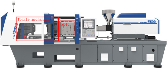
Figure 1.
Electric injection molding machine with a mold. If there are some foreign bodies in the mold without protection, the mold will be damaged when the mold closes. Generally, the mold is expensive, and the maintenance is tedious.
At present, mold protection has attracted many researchers. One research direction is based on machine vision through comparing safe and unsafe situations to detect the foreign bodies. Wang et al. [18] presented a method that applied technologies, such as near infrared illumination technology, the background updating algorithm, and the region of interest, to fulfill . Yang et al. [19] applied key technologies, including the methods for pretreatment of the cavity image, template matching of the cavity image, and cross-correlation of an abnormal cavity situation, into . Chi et al. [20] proposed a system that was able to correctly detect the unsafe in-mold status of the stuck ejectors or pieces by the two approaches of offset correction and dynamic safe range learning. However, the above methods need to add a special vision system. In some high speed cases, processing speed also becomes the issue, and for getting a good effect from image processing, much effort should also be made to implement a customized visual program.
Other improving methods are to avoid failed production based on processing data and mathematical models to reduce the possibility of the entrance of foreign bodies. Based on the monitoring data, Ribeirol et al. [21] proposed an approach for fault detection in a thermoplastic injection molding process to assure a high level of quality control over the molded parts using neural networks. The properties in injection molding can also be controlled by neural networks in [22]. A study in [23] monitored the quality of molded parts in a process from the design and processing points of view. Ribeiro et al. [24] also proposed an approach of support vector machines for quality monitoring in a plastic injection molding process to monitor in-process data and thereby the unexpected process interferences could be responded quickly. These methods are good auxiliary but not the thorough ones for .
IMM controller venders (e.g., Techmation and KEBA) also have their own methods. Those methods just compare electric current () profiles simply, which need to set many parameters (e.g., distance, upper deviation, lower deviation, left deviation, and right deviation). Using those methods, operators always take a long time adjusting parameters, and it is still possible that the mold will be damaged because of misjudgment.
To address the issue, we propose an extended Kalman filter based self-adaptive method. The contributions of this work are as follows:
- The mathematical model of the driven by servo systems () is built used for the process analysis and further researches.
- Through the mathematical model, this paper successfully proposes the , which can be applied in any driven by an .
- The proposed method was implemented in a 140-ton electric injection molding machine (), and decreased the detected distance of by 22% compared with general one.
An extended Kalman filter () linearizes with an estimate of the current mean and covariance, which is a nonlinear kind of the Kalman filter [25,26]. It is widely used in various fields. Jana et al. [27] presented a hybrid FLC-EKF scheme for temperature control of a refinery debutanizer column. Charkhgard et al. [28] used neural networks and EKF to estimate the charging state for Lithium-ion batteries. Fang et al. [29] applied an EKF-based filter fusion method in a high-efficiency motion tracking system. Paolo proposed a two-stage EKF to build an observer for a sensorless control [30]. One key point for using the EKF is the choice of the elements of the covariance matrices, which affects both the performance and the convergence [31]. Many studies [32,33,34] have provided practical approaches and accounts. More details can be found in the surveys of [35,36,37]. However, none of these studies are involved in mold protection problems.
2. Control System of the Toggle Mechanism
A typical control system of is shown in Figure 2. It consists of controller, servo driver, motor, and . The controller contained algorithms and logic programs send commands to the servo driver to drive the motor. The motor is connected to the by a belt or lead screw. We define a servo driver working with a motor as an . In some special cases, two can be used together to provide greater torque. Normally, the communication among the controller, servo driver, and motor adopts a real-time Ethernet bus (e.g., EtherCat).
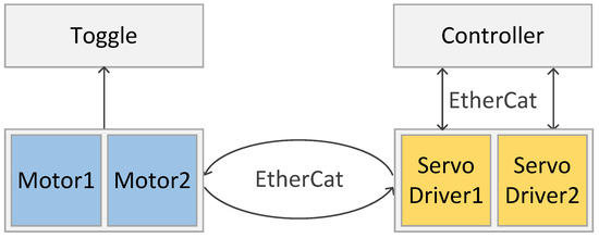
Figure 2.
Control system of a toggle mechanism (), which consists of a controller, servo driver, motor, and . The controller embedded algorithms and logic programs send commands to the servo driver to drive the motor. The motor is connected with the by a belt or lead screw.
A mold is commonly comprised of movable and fixed parts. The movable part is fastened on the . When the machine is power on, the servo system receives commands continuously form the controller to drive the forward or backward. In the servo driver, an encoder is built-in to obtain the actual position and speed. Hence, the controller can gain the feedback (e.g., position, speed, ) from the .
2.1. Mold Protection Problem
Every plastic product is molded by a specific mold. In production, an uses the mold to produce automatically, and every seamless mold close can produce a good product. However, as shown in Figure 3, there may exist a foreign body which will damage the mold. The is to detect the foreign body when a force is quickly pushing the movable mold on. As shown in Figure 3, we defined two key indicators of below.
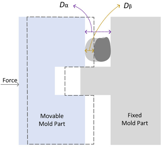
Figure 3.
Damage distance and detected distance.
Definition 1.
(Damage distance): donates the distance between the mold parts when the mold just contacts the foreign body.
Definition 2.
(Detected distance): donates the pressed distance of a foreign body when it is detected.
Hence, the intends to detect the foreign body at a smallest which also means less damage to the mold.
2.2. Servo System
is the power system to drive the . Normally, it contains three closed loops: , speed, and position closed loop. Position closed loop is based on the speed closed loop, and speed closed loop is based on the loop. turns to torque and then provides a force on the actuator. Since the fastened with the movable mold is driven by the force, the should be the key factor for the proposed . The reflects the force on foreign body in the mold and herein could be used to detect the foreign body.
3. EKF Based Model
Regarding the fluctuation of , the is used to filter the . We can obtain the theoretical setting from the user setting trajectory (prediction value), and the drive feedback current (measured value) from the .
3.1. Toggle Mechanism Model
We have shown the model in [13] and herein simply introduced it below.
From the geometry of Figure 4, we can obtain equations as follows:
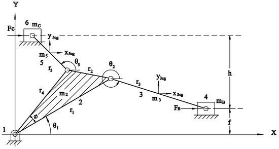
Figure 4.
The physical model of . Establish a Cartesian coordinate system and set the origin at link one. and are the force on sliders B and C, respectively. , , , , and indicate the mass of links two, three, five, and sliders B and C, respectively. , , and indicate the three-side lengths of two, and and indicate the lengths of links three and five respectively; are the angular positions of link two, three, and five; h is the height between the two horizontal guides where sliders B and C travel; and f is an offset between links two and three [13].
describes the parameter relationships in the model. Then, we can obtain
Using Hamilton’s principle, we can obtain
where is the virtual work, and are the generalized constraint reaction forces.
We use energy method to gain dynamic motion equation. The total kinetic energy of the system is described below.
where represent the kinetic energies of link two, three, five, and sliders B and C, respectively.
are calculated as follows:
where is the Lagrange multiplier.
Thus, the equation of motion for the is
Using the Equation (6) and trajectory , we can obtain , and ; for details see the previous paper [13].
3.2. Servo System Model
The model is used to obtain theoretical setting () form . The and torque can be described blew.
where is current and is stator torque constant.
The mechanical equation can be obtained as follows:
where is the force on the slider C in Figure 4, l is the lead of ball screws, and is the screw drive efficiency.
Thus, we can gain the relation between current and force on slider C:
3.3. Process of EKF
Recall that we use the as the filter target, and regard and as the prediction value and measured value, respectively. Thus, we can obtain the equations of state time propagation and state measurement propagation as follows:
where r is the process standard deviation, and q is the measurement standard deviation.
Then we can get the Jacobian matrix and .
The covariance updating equation of is described below.
where is the transpose matrix of F, Q is the process variance.
According to the setting profile and feedback current, the current optimal estimation can be obtained.
where is Kalman gain, and it can be calculated using the following equation.
where R is the measurement variance.
To keep the running until the end of the system process, the covariance updating equation of is needed.
where I is a unit matrix.
3.4. Self-Adaptive Model
The based self-adaptive method () is used to gain the safety range of the current curve. In , according to mathematical model of driven by , the setting profile is chosen as the prediction value, and the drive feedback current is chosen as the measurement value. At first, the should ensure the absence of foreign bodies, and then injection machine mold close and open automatically according to self-adaptive time n. Every current curve will be saved in a -dimensional matrix, . m is the time of sample, and the position of every sampled point is saved in a m-dimensional matrix, P. Equation (17) records the data to calculate the standard current curves.
where is one time current curve optimized by .
Then, we can get the safety range of current curve as follows.
where and are functions to get the maximum and minimum values of every sampled point, respectively. U and L are upper deviation current curve and lower deviation current curve, respectively; and the dimension of U and L is m. is true error.
Regarding Equation (18), the safety range at every position should be between the maximum and minimum currents within n self-adaptive processes. Note that is necessary because the self-adaptive time n is limited. However, because of the unknown of the true error value, the error value is calculated by the Bessel formula below.
where is the arithmetic mean of n-time curves.
When the is running in checking area, it will be checked whether the actual current curve is between the two curves. If not, the machine will stop closing and then open to protect the mold.
3.5. Process of the Self-Adaptive Method
The process of the self-adaptive method is divided two phases: training and applied phases; see Figure 5. From the perspective of the training phase, setting trajectory is executed in the system several times, which must be under the condition without MMP. Every time is put into system and our mathematical model, the can gain and to produce accurate EC. Then, the SAM uses the accurate ECs to produce safety range of current curve.
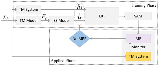
Figure 5.
Process of the self-adaptive method.
After the training, the can be used to judge whether the MMP occurs—the applied phase. In this phase, the is put into system. Meanwhile, the proposed method monitors the system as to whether any occurs or not. If no happens, the and produced can be used to update the . Otherwise, the mold will open and give tips in the human machine interface (HMI).
4. Experimental Results
Experimental equipment and the control process are shown in Figure 6. The primary facility was a 140-ton , driven by . Data analysis was done in a Dell laptop which had a clock speed of 1.7 GHz and 4 GB DDR3 RAM. The controller was KEBA CP052 implemented the Ethercat protocol, and it used 24 v to control input and output. The servo drive was a Phase AXN 70.140.4, and the motor was a Phase U31013F.15.3 N7, whose maximum speed was 3000 RPM. An encoder built in the motor was used to feed back the position. In Figure 6, an experiment with a disposable cup is shown, which verifies the effectiveness of the method intuitively. Table 1 shows the parameters of the , , and in the experiment. Based on those parameters, the following experiments were done.
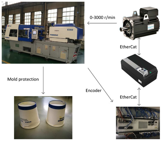
Figure 6.
Experimental facility, control process, and effect of .

Table 1.
Parameters of the , , and in the experiment.
In our experiment, the s-curve was chosen as the start and stop slope. We set the speed and acceleration of mold open and mold close to 500 mm/s and 2 m/s2, which are very fast times in real production. The displacement was set to 240 mm. In the section of , the setting profile was chosen as the prediction value, and the drive feedback current was chosen as the measurement value.
Figure 7 shows the displacement, velocity, acceleration, and force on slider C, which were calculated from the setting profile.
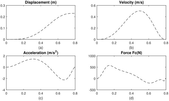
Figure 7.
(a–d) The displacement, velocity, acceleration, and force on slider C, respectively, which all change over time.
When using , the r was 0.01, q was 0.02, and protection monitor displacement was 7 mm. Then we tested the first effect of , and Figure 8 is the effect of current profile filtered by . Plus icons are measurement values. The green profile is the setting value after being calculated by our mathematical model. The blue profile is the optimized estimated value.
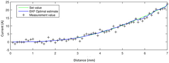
Figure 8.
The effect of a current profile filtered by .
In self-adaptive part, we set the learning time to 50. Figure 9 shows the result. The blue profiles are the 50 curves filtered by . The red profile is the upper deviation curve, and the purple one is the lower deviation curve.
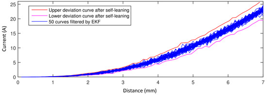
Figure 9.
Result of self-adaptive mold protection method. The blue profiles are the 50 curves filtered by . The red profile is upper deviation curve, and the purple one is the lower deviation curve.
In the next step, we took three experiments. In these experiments, we put three foreign bodies of different thicknesses into a mold individually, whose thicknesses () were 1, 0.8, and 0.5 mm, respectively. Figure 10 shows the results. In case of 1 mm, it checked out the thickness was within a 0.16 mm range after touching the foreign body; i.e., = 0.16. In cases of 0.8 mm and 0.5 mm, the were 0.12 mm and 0.10 mm, respectively.
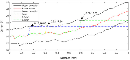
Figure 10.
Current profiles when the mold closes with foreign bodies of different thicknesses.
In the last part, we compared precision of the proposed and general methods. In the contrast experiment, the thickness of each foreign body was arbitrary, and we tested the proposed method and the general one 100 times respectively. Figure 11 shows the results. In these 100 experiments, the average of proposed method was 0.94 mm, while the general one was 1.21 mm, which is a decrease of 22%.
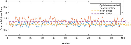
Figure 11.
Detection precision comparison of the based self-adaptive method and general one for 100 rounds. The thickness of each foreign body was arbitrary. Through 100 experiments, the average detected distance of the proposed method was 0.94 mm, while that of the general one was 1.21 mm. Namely, the detected distance of the proposed method was decreased by 22%.
5. Conclusions
The mold protection problem is bothering engineers because of the high maintenance price and time-consuming maintenance process. Vision-based methods need an additional vision system, and customized algorithms. Without a vision system, existing methods always take a lot of time for field engineers to adjust mold protection parameters. Therefore, we proposed an EKF-based self-adaptive method in this paper. We built a mathematical model for a toggle mechanism driven by servo systems. Using the rough values from the mathematical model and toggle mechanism system, we applied the EKF to obtain an accurate electric current. Then a self-adaptive method was proposed to obtain the safety current range. At last, the proposed method was implemented in a 140-ton , and the results showed that the detected distance of foreign bodies was decreased by 22% compared with the general method.
In future, a combination of the vision and proposed methods will be studied to further improve the robustness and sensitivity of the for higher speed applications.
Author Contributions
Conceptualization, B.C. and H.W.; methodology, D.S.; software, B.C.; validation, H.Z. and D.S.; formal analysis, B.C. and D.S.; investigation, B.C.; resources, H.Z.; data curation, B.C.; writing—original draft preparation, B.C. and D.S.; writing—review and editing, H.W. and H.Z.; visualization, D.S.; supervision, H.W.; project administration, H.W.; funding acquisition, H.W. All authors have read and agreed to the published version of the manuscript.
Funding
This work was supported in part by the National Natural Science Foundation of China (U1609211).
Conflicts of Interest
The authors declare no conflict of interest.
Abbreviations
The following abbreviations are used in this manuscript:
| EMP | Extended kalman filter based mold protection |
| EKF | Extended kalman filter |
| TM | TOGGLE MECHANISM |
| SAM | Self-adaptive method |
| IMM | Injection molding machine |
| SS | Servo system |
| MP | Mold protection |
| EIMM | Electric injection molding machine |
| MPP | Mold protection problem |
| EC | Electric current |
References
- Cheng, Y.; Zhang, Y.; Ji, P.; Xu, W.; Zhou, Z.; Tao, F. Cyber-physical integration for moving digital factories forward towards smart manufacturing: A survey. Int. J. Adv. Manuf. Technol. 2018, 97, 1209–1221. [Google Scholar] [CrossRef]
- Bangemann, T.; Riedl, M.; Thron, M.; Diedrich, C. Integration of classical components into industrial cyber–physical systems. Proc. IEEE 2016, 104, 947–959. [Google Scholar] [CrossRef]
- Lamarre, S.G.; Demers, V.; Chatelain, J.F. Low-pressure powder injection molding using an innovative injection press concept. Int. J. Adv. Manuf. Technol. 2017, 91, 2595–2605. [Google Scholar] [CrossRef]
- Wang, X.; Zhang, Y.; Shen, G. An improved FMECA for feed system of CNC machining center based on ICR and DEMATEL method. Int. J. Adv. Manuf. Technol. 2016, 83, 43–54. [Google Scholar] [CrossRef]
- Fuentes-Huerta, M.A.; González-González, D.S.; Cantú-Sifuentes, M.; Praga-Alejo, R.J. RCM implementation on plastic injection molding machine considering correlated failure modes and small size sample. Int. J. Adv. Manuf. Technol. 2018, 95, 3465–3473. [Google Scholar] [CrossRef]
- Fung, R.F.; Hwang, C.C.; Huang, C.S.; Chen, W.P. Inverse dynamics of a toggle mechanism. Comput. Struct. 1997, 63, 91–99. [Google Scholar] [CrossRef]
- Wai, R.; Lin, C.; Lin, F. Adaptive fuzzy neural network control for motor-toggle servomechanism. Mechatronics 2001, 11, 95–117. [Google Scholar] [CrossRef]
- Lin, F.; Fung, R.; Wang, Y. Sliding mode and fuzzy control of toggle mechanism using PM synchronous servomotor drive. IEE Proc. Control Theory Appl. 1997, 144, 393–402. [Google Scholar] [CrossRef]
- Wai, R.J. Hybrid fuzzy neural-network control for nonlinear motor-toggle servomechanism. IEEE Trans. Control Syst. Technol. 2002, 10, 519–532. [Google Scholar]
- Chuang, C.W.; Huang, M.S.; Chen, K.Y.; Fung, R.F. Adaptive vision-based control of a motor-toggle mechanism: Simulations and experiments. J. Sound Vib. 2008, 312, 848–861. [Google Scholar] [CrossRef]
- Gasparetto, A.; Zanotto, V. A new method for smooth trajectory planning of robot manipulators. Mech. Mach. Theory 2007, 42, 455–471. [Google Scholar] [CrossRef]
- Boscariol, P.; Gasparetto, A. Optimal trajectory planning for nonlinear systems: Robust and constrained solution. Robotica 2016, 34, 1243–1259. [Google Scholar] [CrossRef]
- Wu, H.; Sun, D. High precision control in PTP trajectory planning for nonlinear systems using on high-degree polynomial and cuckoo search. Optim. Control Appl. Methods 2019, 40, 43–54. [Google Scholar] [CrossRef]
- Engleder, S. Time-optimal motion planning and control of an electrohydraulically actuated toggle mechanism. Mechatronics 2007, 17, 448–456. [Google Scholar] [CrossRef]
- Chiang, M.H.; Chen, C.C.; Kuo, C.F.J. The high response and high efficiency velocity control of a hydraulic injection molding machine using a variable rotational speed electro-hydraulic pump-controlled system. Int. J. Adv. Manuf. Technol. 2009, 43, 841–851. [Google Scholar] [CrossRef]
- Hsu, Y.L.; Huang, M.S.; Fung, R.F. Energy-saving trajectory planning for a toggle mechanism driven by a PMSM. Mechatronics 2014, 24, 23–31. [Google Scholar] [CrossRef]
- Pellicciari, M.; Berselli, G.; Balugani, F.; Gadaleta, M. Increasing position accuracy and energy efficiency of servo-actuated mechanisms. In Proceedings of the 2015 IEEE International Conference on Automation Science and Engineering (CASE), Gothenburg, Sweden, 24–28 August 2015; pp. 1339–1344. [Google Scholar]
- Wang, P.J.; Xu, C.J.; Chen, J.H.; Tang, X.Q. Injecting mold protection method based on machine vision. Adv. Mater. Res. 2012, 590, 475–482. [Google Scholar]
- Ding, Y.; Wei, Y.; Yun, Z. Detection of Cavity Abnormal Situation for Injection Mold Based on Machine Vision. Eng. Plast. Appl. 2014, 4, 74–77. [Google Scholar]
- Chi, T.Y.; Huang, C.Y.; Xin, M.C. An In-Mold Monitoring and Protection System of the Injection Molding Machine Using Offset Correction and Dynamic Safe Range Learning Approach. In Proceedings of the 2015 First International Conference on Computational Intelligence Theory, Systems and Applications (CCITSA), ILan, Taiwan, 10–12 December 2015; pp. 64–68. [Google Scholar]
- Ribeiro, B. Fault detection in a thermoplastic injection molding process using neural networks. In Proceedings of the IJCNN’99 International Joint Conference on Neural Networks, Washington, DC, USA, 10–16 July 1999; Volume 5, pp. 3352–3355. [Google Scholar]
- Kenig, S.; Ben-David, A.; Omer, M.; Sadeh, A. Control of properties in injection molding by neural networks. Eng. Appl. Artif. Intell. 2001, 14, 819–823. [Google Scholar] [CrossRef]
- Min, B. A study on quality monitoring of injection-molded parts. J. Mater. Process. Technol. 2003, 136, 1–6. [Google Scholar] [CrossRef]
- Ribeiro, B. Support vector machines for quality monitoring in a plastic injection molding process. IEEE Trans. Syst. Man Cybern. Part C (Appl. Rev.) 2005, 35, 401–410. [Google Scholar] [CrossRef]
- Kalman, R.E. Contributions to the theory of optimal control. Bol. Soc. Mat. Mex. 1960, 5, 102–119. [Google Scholar]
- Kalman, R.E. A new approach to linear filtering and prediction problems. J. Basic Eng. 1960, 82, 35–45. [Google Scholar] [CrossRef]
- Jana, A.K. A hybrid FLC-EKF scheme for temperature control of a refinery debutanizer column. IEEE Trans. Ind. Inform. 2009, 6, 25–35. [Google Scholar] [CrossRef]
- Charkhgard, M.; Farrokhi, M. State-of-charge estimation for lithium-ion batteries using neural networks and EKF. IEEE Trans. Ind. Electron. 2010, 57, 4178–4187. [Google Scholar] [CrossRef]
- Fang, W.; Zheng, L.; Xu, J. Self-contained optical-inertial motion capturing for assembly planning in digital factory. Int. J. Adv. Manuf. Technol. 2017, 93, 1243–1256. [Google Scholar] [CrossRef]
- Mercorelli, P. A two-stage augmented extended Kalman filter as an observer for sensorless valve control in camless internal combustion engines. IEEE Trans. Ind. Electron. 2012, 59, 4236–4247. [Google Scholar] [CrossRef]
- Mercorelli, P. A hysteresis hybrid extended Kalman filter as an observer for sensorless valve control in camless internal combustion engines. IEEE Trans. Ind. Appl. 2012, 48, 1940–1949. [Google Scholar] [CrossRef]
- Haus, B.; Aschemann, H.; Mercorelli, P. Tracking control of a piezo-hydraulic actuator using input–output linearization and a cascaded extended kalman filter structure. J. Frankl. Inst. 2018, 355, 9298–9320. [Google Scholar] [CrossRef]
- Zarchan, P.; Musoff, H. Fundamentals of Kalman filtering: A Practical Approach; American Institute of Aeronautics and Astronautics, Inc.: Washington, DC, USA, 2013. [Google Scholar]
- Schimmack, M.; Haus, B.; Mercorelli, P. An Extended Kalman Filter as an Observer in a Control Structure for Health Monitoring of a Metal–Polymer Hybrid Soft Actuator. IEEE/ASME Trans. Mechatronics 2018, 23, 1477–1487. [Google Scholar] [CrossRef]
- Budhiraja, A.; Chen, L.; Lee, C. A survey of numerical methods for nonlinear filtering problems. Phys. D Nonlinear Phenom. 2007, 230, 27–36. [Google Scholar] [CrossRef]
- Simon, D. Kalman filtering with state constraints: A survey of linear and nonlinear algorithms. IET Control Theory Appl. 2010, 4, 1303–1318. [Google Scholar] [CrossRef]
- Chen, S. Kalman filter for robot vision: A survey. IEEE Trans. Ind. Electron. 2011, 59, 4409–4420. [Google Scholar] [CrossRef]
© 2020 by the authors. Licensee MDPI, Basel, Switzerland. This article is an open access article distributed under the terms and conditions of the Creative Commons Attribution (CC BY) license (http://creativecommons.org/licenses/by/4.0/).