Abstract
In the presence of manufacturing errors, the dynamic properties of herringbone planetary gear train (HPGT) can be altered from the originally designed properties to have undesired behavior. In this paper, by considering the herringbone gear actual structure characteristics, manufacturing eccentric errors of members (i.e., carrier and gears) and tooth profile errors of gears, time-varying meshing stiffness, bearing deformation, and gyroscopic effect, a novel lateral–torsional–axial coupling dynamic model for the herringbone planetary gear system is formulated by using the lumped-parameter method, which is able to be employed in the dynamic feature analysis of the HPGT with an arbitrary number of planets and different types of manufacturing errors. By applying the variable-step Runge–Kutta algorithm, the dynamic response of a HPGT system is studied for cases with and without planet–gear eccentric error excitations. The dynamic contact forces of gears and bearings are analyzed for the two cases in time and frequency domains, respectively. Moreover, the effect of the planet–gear eccentricity on the vibration accelerations of the HPGT system is also discussed. The obtained results indicate that manufacturing error excitations such as the planet–gear eccentricity have a pronounced influence on the dynamic behavior of the HPGT system.
1. Introduction
Owing to the characteristics of power split flow, compactness, and high torque-to-weight ratio, planetary gear train (PGT) is extensively employed in various industrial applications, such as in aerospace, automobiles, wind turbines, and nuclear power plants. In contrast to spur or helical gears, herringbone gears possess many benefits, including smoother transmission, lower axial force, and greater transmission torque. Consequently, the herringbone planetary gear system has also been used in the power train of heavy machinery such as aerospace engines, and long-wall shearers. The existence of inevitable processing errors in the manufacturing process of a drive train can significantly affect the reliability and durability of herringbone planetary gears. Nevertheless, there have been few related reports on the manufacturing error impacts on the dynamic properties of herringbone planetary gears. For the sake of achieving reliable and quiet operation, it is vital and necessary to formulate a dynamic model of herringbone planetary gears for the analysis of manufacturing error effects on dynamic properties.
There have been several investigations into the PGT dynamic properties. Lin and Parker constructed a spur PGT dynamic model to examine the modal characteristics [1,2]. Guo established an analytical model of spur PGTs with bearing backlash nonlinearity and tooth wedging [3]. Zhao and Ji proposed a nonlinear torsional model of multi-stage spur PGTs applied to a wind turbine gearbox for the analysis of nonlinear vibration characteristics [4]. Kahraman presented an analytical model for a stage of helical PGT for the study of its dynamic behavior [5]. Based on the lumped-parameter and finite element theories, Tatar et al. constructed a three-dimensional analytical model of helical planetary geared rotor sets by considering gyroscopic effects to investigate the dynamic behavior [6]. Bu incorporated journal bearings to a dynamic model of herringbone planetary gears to study their modal properties [7]. Sondkar and Kahraman investigated the free and forced vibration characteristics of double-helical planetary gears [8]. Chaari considered the eccentric and profile errors and examined the manufacturing error impacts on the spur PGT dynamic properties [9]. Xu studied the influences of pin error and stiffness in wind turbine gearbox on the PGT load distribution performance [10]. Ren et al. conducted a study of the manufacturing error effects on dynamic performance and load distribution properties for HPGT [11,12,13,14]. Zhu et al. explored the impact of meshing-frequency and run-out errors on dynamic load distribution among different planets for encased differential gear sets [15].
However, there has been no research on the impact of manufacturing errors such as the planet–gear eccentricity on the dynamic properties for herringbone planetary gears. In this paper, by considering the actual structural features of herringbone gears, a novel transverse-axial-torsional coupling dynamic analytical model for herringbone planetary gears involving manufacturing errors is formulated by applying the lumped-parameter method. The dynamic features of a HPGT system are then numerically studied, and the impacts of manufacturing errors such as the planet–gear eccentricity on the dynamic performance are examined.
2. Components and Drive Principle
The schematic of the components and drive principle of the herringbone planetary gear is shown in Figure 1, which are composed of a sun gear s, a planet–carrier c, a right ring gear r1, a left ring gear r2, and N uniform planet gears p. Here, the sun gear connects with the high-speed input shaft, while the carrier is linked with the low-speed output shaft. The sun gear is subjected to the input torque and eventually the power is transmitted to the external load by the carrier as an output. The planets and sun adopt the herringbone gears, whereas the left and right stationary ring gears use two internal helical gears possessing opposite helical angles.
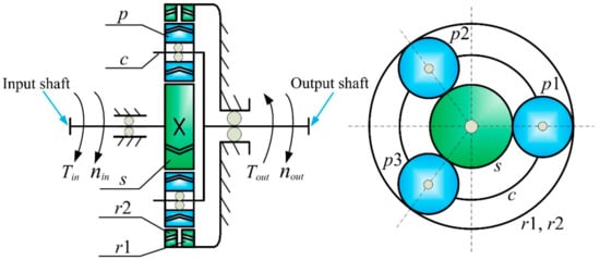
Figure 1.
Structural diagram of herringbone planetary gears.
3. Dynamic Model and Equations of Motion
3.1. Dynamic Model
Figure 2 shows the developed transverse-axial-torsional coupling dynamic model of the herringbone planetary gear set. All the gears (i.e., the sun, two rings, and planets) and the planet–carrier are considered to be rigid bodies. Bearing components are modeled by linear springs between their housings and bodies. Linear springs applied along the action line denote gear mesh interactions. The damping, gravity and friction impact are neglected, and the tilting motion is ignored. Each member possesses four degrees of freedom (DOFs), including one axial translation, two lateral translations, and one rotation. As demonstrated in Figure 2, there are three kinds of reference frames established, namely (1) the static reference frame OXYZ, (2) the dynamic reference frame Oxyz rotating around the coordinate origin O together with the carrier, and (3) the dynamic reference frame Oixiyizi rotating with the carrier, whose origin Oi is at the ith planet–gear’s center, and xi-, yi-axis are, respectively, in the radial and tangential direction.
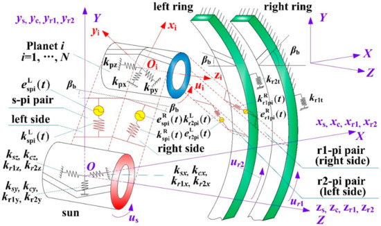
Figure 2.
Bending-torsional-axial coupling dynamic model of herringbone planetary gears taking both sides of each gear into consideration. For simplicity, only one planet–gear is exhibited and the carrier is not displayed in the figure.
Translational coordinates xi, yi, zi (i = c, r1, r2, s) are respectively assigned to the carrier, right ring gear, left ring gear, and sun gear. Rotational coordinates are given by where is the rotation; (i = r1, r2, s, 1, 2,..., N) are, respectively, the base radius for the right ring, left ring, sun and planets, and is the circle radius from the center of each planet–gear to that of the carrier. Translational coordinates xj, yj, zj (j = 1, s…, N) are assigned to the jth planet–gear, denoting the absolute radial, tangential, and axial deflections of the jth planet–gear. The vector [xs, ys, zs, us, xr1, yr1, zr1, ur1, xr2, yr2, zr2, ur2, xc, yc, zc, uc, x1, y1, z1, u1,…, xN, yN, zN, uN]T is selected as the generalized coordinates to create the lumped-parameter dynamic analytical model for the HPGT system. denotes the transverse pressure angle. e represents the static transmission error. k denotes the stiffness. represents the installation position angle of the planet i, and is assumed to be positive when anticlockwise. is the base helix angle. Symbols L and R respectively represent the left side and right side of the herringbone gears in the HPGT system. spi denotes the ith external meshing pair. r1pi and r2pi stand for the ith right- and left-side internal meshing pairs, respectively.
3.2. Component Acceleration Analysis in HPGT
To conduct the dynamic analysis, the acceleration analysis of each component for herringbone planetary gears should be first carried out. The generalized coordinates of herringbone planetary gears are established in the dynamic reference frames rotating along with the carrier. However, the accelerations of component centroids used in the dynamic analysis should be the absolute acceleration, so the absolute acceleration expressed in the dynamic coordinate systems should be derived. The relationship among the reference frames is displayed in Figure 3.
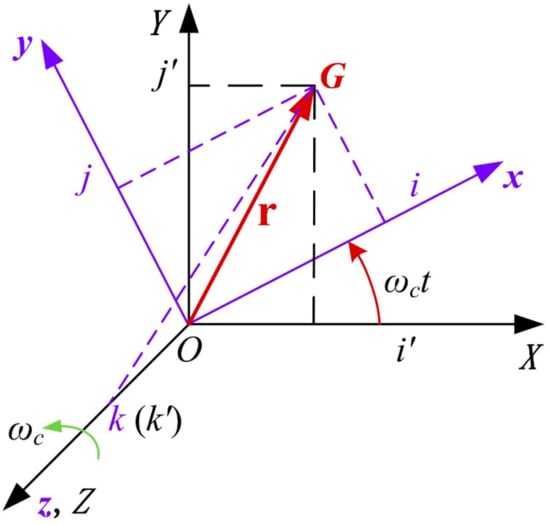
Figure 3.
Coordinate transformations.
Let G be the assumed centroid. Since the origin of the static reference frame {i’, j’, k’} and the origin of the dynamic reference frame {i, j, k} coincide at point O, the radius vectors of G are both expressed by r in these two reference frames and . The components in the dynamic reference frame of the vector r are, respectively, x·i, y·j and z·k, and those in the static reference frame are, respectively, X·i’, Y·j’ and Z·k’. From Figure 3, the radius vector can be obtained as
The absolute acceleration of G can be written as
The absolute acceleration of G in the dynamic reference frame can be derived as
where means the angular velocity of the carrier. and represent the Coriolis accelerations of G. and denote the centripetal accelerations.
3.3. Component Equivalent Displacements in HPGT
Figure 4, Figure 5 and Figure 6 respectively show the dynamic models of the external (sun-planet i) and internal (carrier-planet i) mesh pair, and carrier-planet i pair. In the derivation of the dynamic equations of the entire HPGT system, the relative displacements between the components in HPGT need to be obtained first. According to the motion and deformation relationships between components as shown in Figure 4, Figure 5 and Figure 6, the relative displacements can be deduced [16,17,18,19,20,21].
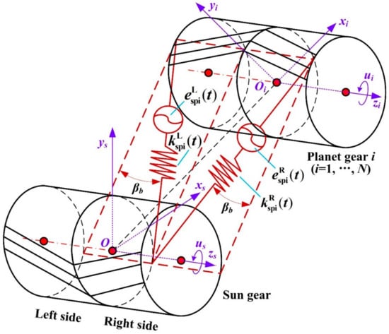
Figure 4.
Dynamic model of the ith herringbone planet-sun gear pair.
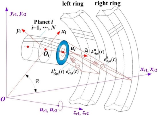
Figure 5.
Dynamic model of the ith herringbone planet-ring gear pair.
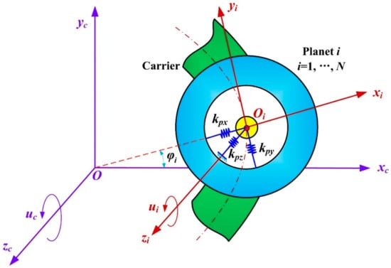
Figure 6.
Dynamic model of the ith herringbone planet–carrier pair.
- (1)
- The equivalent deformation of the ith external mesh on the left side is written as
- (2)
- The equivalent deformation of the ith external mesh on the right side is expressed as
- (3)
- The equivalent deformation of the ith left-side internal mesh is given by
- (4)
- The equivalent deformation of the ith right-side internal mesh is written as
- (5)
- The radial relative deflection between the ith planet and the carrier is determined by
- (6)
- The tangential relative deflection between the ith planet and the carrier is expressed as
- (7)
- The axial relative deflection between the ith planet and the carrier is given by
3.4. Equations of Motion
Based on the dynamic models of each mesh pair as displayed in Figure 4, Figure 5 and Figure 6, Newton’s Second Law of Motion in non-inertial coordinate frames [2] is employed to acquire the equations of motion for herringbone planetary gears. The carrier’s motion equations can be given by
In a similar manner, the equations of motion of the other components for herringbone planetary gears can be derived.
The right ring gear’s motion equations are represented by
The left ring gear’s motion equations can be expressed as
The sun gear’s motion equations are given by
The ith planet–gear’s motion equations can be derived as
where mg and Jg (g = s, p, c, r) represent the mass and rotational inertia of member g, respectively. N refers to the plane number. kn and knz are the x- or y-direction and z-direction support stiffness of member n (n = s, p, c, r1, r2), respectively. knt (n = r1, r2) respectively means the torsional support stiffness of the right and left ring gear. and stand for the meshing stiffness of the ith external and internal meshing pairs on the left and right sides, respectively.
The motion equations of the dynamic model exhibited in Figure 2 can be rewritten in matrix form as
where and respectively represent the HPGT generalized displacement, velocity and acceleration vectors and {xs, ys, zs, us, xr1, yr1, zr1, ur1, xr2, yr2, zr2, ur2, xc, yc, zc, uc, x1, y1, z1, u1,…, xN, yN, zN, uN}T. refers to the HPGT generalized mass matrix, is the bearing stiffness matrix. indicates the time-varying meshing stiffness matrix where represents the gyroscopic matrix. is the centripetal stiffness matrix. denotes the HPGT load vector including the internal exciting force vector which arises from the static transmission error due to elastic deflections and manufacturing errors. T is the HPGT external exciting force vector and T = {0, 0, 0, Ts/rs, 0, 0, 0, 0, 0, 0, 0, 0, 0, 0, 0, −Tc/rc, 0, 0, 0, 0,…, 0, 0, 0, 0}T, where Tg (g = s, c) is the external torques applied on the component g.
4. Internal Excitations
4.1. Error Excitation
This paper considers the manufacturing eccentric errors of each member (i.e., carrier and each gear) as well as tooth profile errors of each gear. These manufacturing errors are projected to the contact lines of the left-side and right-side meshing pairs of the HPGT system, respectively, and finally the cumulative meshing error gained by the superposition of eccentric and tooth profile error of components at the left- and right-side action lines can be written as [11,12].
where and represent the cumulative meshing errors for the ith left- and right-side external and internal meshing pairs, respectively; and denote the amplitudes of eccentric errors of members; and are the eccentric error initial phases of members; and are the amplitudes of profile errors for each gear pair; is the angle velocity of member g; t is time. is the system meshing angular frequency, Tm is the system meshing period.
4.2. Time-Varying Meshing Stiffness Excitation
For a HPGT system, based on the mesh stiffness formula of helical gears, the time-varying meshing stiffness for the ith left- and right-side internal and external meshing pairs of the system can be denoted as the first-order Fourier series form as described in Equation (18), respectively [11,12,22].
where and all denote the first-order Fourier coefficients, the notation represents the average meshing stiffness. Furthermore, this paper considers the relationships of planet meshing phases, which are involved in the Fourier coefficients .
5. Numerical Calculation Approach
Since the numerical integration method is widely used, which is suitable for solving any type of nonlinear differential equations, and in engineering practice, the differential equations of gear system dynamics are generally difficult to obtain accurate analytical solutions, the numerical methods have been widely applied in solving the dynamic equations of complex gear systems, where the Runge–Kutta method is the main numerical integration method.
In the present paper, the system response is solved by using the variable-step Runge–Kutta algorithm [11,12]. To apply Runge–Kutta method to solve Equation (16), first, the descending order processing of second order differential equations is needed to transform the governing Equation (16) into a state equation of first derivative form. Thus, Equation (16) can be rewritten as
Introducing the state vector
Equation (19) can be written as a matrix form of first-order ordinary differential equations
while calculating, based on the above Equation (21), the ODE solver in MATLAB is used to solve the system equation.
6. Numerical Simulations
The parameters of a herringbone planetary gear with both stationary rings and three equally spaced planets shown in Figure 1 are given in Table 1 and Table 2. The variable-step Runge–Kutta method described in Section 5 is employed for solving the system Equation (16). The dynamic responses such as the vibration accelerations of the components of the HPGT system are compared for two cases where the planet–gear eccentric error excitations are present and absent. Furthermore, the dynamic contact forces of gear and bearing for the HPGT system are also compared between the results with and without planet–gear eccentric error excitations in the time domain and frequency domain, respectively.

Table 1.
Parameters of the HPGT system.
Table 2.
HPGT stiffness parameters.
To investigate the impacts of planet–gear eccentricity Ep1 on the HPGT dynamic features, the planet–gear eccentric error is assumed to be Ep1 = 100 μm, while the other manufacturing errors are not considered. The planet–gear eccentricity is defined to be the deviation between the realistic and theoretical rotational center as depicted in Figure 7 which shows a schematic of the planet–gear eccentricity.
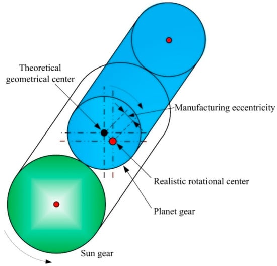
Figure 7.
Definition of the planet–gear eccentricity.
6.1. Dynamic Meshing Forces
Figure 8 illustrates the time-domain responses of the dynamic meshing force on the right-side planet-sun gear pair, which is represented as (, where and are the same as those in Equations (5) and (18)), for two cases of with and without planet–gear eccentric error. For the sake of clarity, just one side of the dynamic meshing forces of a part of the time interval for the HPGT is demonstrated in Figure 8. It can be observed from Figure 8 that because the input torque of the system Tin = 100 KN·m is constant, the dynamic meshing forces of the right-side meshing pair possess no low-frequency components for both models with and without the planet–gear eccentric error excitations. The average values of the dynamic meshing forces for the models with and without the planet–gear eccentric error excitations are approximately 57 KN as shown by the red dot-dash lines in Figure 8a,b. A comparison of Figure 8a,b indicates that the meshing force fluctuation amplitude from the model with the planet–gear eccentric error excitation Ep1 = 100 μm is obviously larger than that without error excitations. That is to say, the planet–gear eccentric error excitation increases the meshing force amplitude significantly in contrast to the model without manufacturing error excitations. The similar tendency is also able to be discovered for the meshing forces on one side of internal (planet-ring) meshing pair. In short, the planet–gear eccentric error excitation prominently increases the dynamic meshing force fluctuation amplitude for herringbone planetary gears.
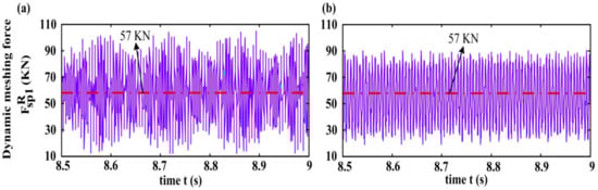
Figure 8.
Variation of the dynamic meshing force on the right-side external meshing pair with gear mesh time, expressed as . (a) the model with the planet–gear eccentric error excitation Ep1 = 100 μm, (b) the model without error excitations.
Figure 9 presents the dynamic meshing force frequency spectra on the right-side external (planet-sun) meshing pair, where (a) and (b) show the results for the model with and without the planet–gear eccentric error excitations, respectively, which are acquired using the signal processing method of fast Fourier transform (FFT) to transform the time domain response as shown in Figure 8 into the frequency domain. For the model with the planet eccentricity, it is found from Figure 9a that some main frequencies of 27.3 Hz, 133 Hz, 162 Hz, 213 Hz, 232 Hz, 507 Hz, 613 Hz, 1187 Hz, and 1523 Hz appear in the right-side dynamic meshing force frequency spectra. The peak value of frequency spectra at the frequency of 0 Hz is maximum, and it is the direct current component of . As is shown in Figure 9a, the dynamic meshing force amplitude at the frequency of 0 Hz is 57 KN, which is exactly the same as the average value of the dynamic meshing force in the time domain shown in Figure 8. In addition, at 162 Hz is associated with the 7th order natural frequency in HPGT, and the peak value of frequency spectra is the second highest. The 133 Hz, 213 Hz, 232 Hz, 507 Hz, 613 Hz, 1187 Hz, 1523 Hz, and 27.3 Hz are associated with the 5-, 8-, 9-, 14-, 16-, 22-, 26-th natural frequencies and the mesh frequency of the HPGT system, respectively. Therefore, it can be concluded that in the model with the planet eccentricity, as shown in Figure 9a, the dynamic meshing force frequency spectrum demonstrates the appearance of larger amplitudes at the meshing frequency and some natural frequencies of HPGT. The frequency spectrum characteristics of dynamic meshing force are in fairly good agreement with the results of modal analysis. Figure 9b displays the frequency spectrum from the model without error excitations. By comparing Figure 9a,b, it is noted that the variation amplitudes of dynamic mesh forces with the planet eccentricity excitation are remarkably greater than those without error excitations. Thus, the manufacturing error excitations such as the planet eccentricity enhance the meshing force fluctuation.
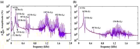
Figure 9.
Frequency spectra of the dynamic meshing force at the right-side gear pair. (a) the model with the planet–gear eccentric error excitation Ep1 = 100 μm, (b) the model without error excitations.
6.2. Dynamic Bearing Forces
Figure 10 illustrates the variation of the bearing forces of some main components involving the carrier, sun and planet in the HPGT system with gear mesh time (denoted as Fc, Fs, and Fp1, respectively). For the model with the planet–gear eccentric error excitation, as displayed in Figure 10a–c, it is observed that dynamic bearing forces for each component (carrier, sun and planet–gear) fluctuate prominently and periodically. The variation of the planet–gear dynamic bearing force is the most significant in each component of the system, and the variation of the sun gear bearing force is relatively smaller, owing to better flexible support of the sun gear. Figure 10d–f represent the dynamic bearing force from the model without manufacturing error excitations. A comparison of Figure 10d–f with Figure 10a–c shows the amplitudes of the dynamic bearing forces for each component in the presence of the planet eccentricity excitations are pronouncedly bigger than those in the absence of error excitations. In contrast to the results for the model in the absence of error excitations, the dynamic bearing forces of each component with the planet–gear eccentric error excitations have larger cyclical fluctuations; in particular, the variations of the planet–gear dynamic bearing forces are the most obvious in comparison with other components (carrier, sun gear), and the maximum amplitude of dynamic bearing forces of the planet–gear changes from 4.5 × 10⁴ N without error excitation, as shown in Figure 10f, to 7.8 × 10⁴ N with the planet–gear eccentric error excitation displayed in Figure 10c, that of the carrier from 0.25 × 10⁴ N without errors shown in Figure 10d to 1.8 × 10⁴ N with errors shown in Figure 10a, with more obvious changes, and that of the sun gear from 0.1 × 10⁴ N without error excitation shown in Figure 10e to 0.6 × 10⁴ N with error excitation shown in Figure 10b, also with more significant variations. By comparing Figure 10a–c with Figure 10d–f, it is noted that manufacturing error excitations such as the planet–gear eccentric error enhance the dynamic bearing force fluctuation for each component in HPGT system, and the dynamic bearing force fluctuation for each component shows apparent periodicity.
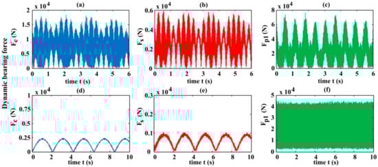
Figure 10.
Variation of the dynamic bearing forces of main components ((a,d) carrier, (b,e) sun, and (c,f) planet) with gear mesh time, which are represented as Fc, Fs, and Fp1, respectively. (a–c) the model with the planet–gear eccentric error excitation Ep1 = 100 μm; while (d–f) the model without error excitations.
6.3. Vibration Accelerations of the Components
Figure 11 illustrates the variations of the accelerations in x-, y-, z-, and u-directions for some main components of HPGT (i.e., the carrier, sun and planet) with gear mesh time (denoted as aix, aiy, aiz, aiu (i = c, s, p1), respectively), which reflect the vibrations of main system components involving the carrier, sun, and planet in the corresponding directions, respectively, for the case of the planet eccentricity Ep1 = 100 μm, while Figure 12 shows the results for the case of without error excitations. For the model with the planet–gear eccentric error excitation, the time-domain vibration accelerations at each degree of freedom of system components behave the fluctuation up and down around the horizontal zero axis; the component vibration accelerations in the z-direction (i.e., axial direction) are pronouncedly smaller than in the lateral directions (i.e., x, y-direction), induced by the symmetrical tooth structure of herringbone gear, making the axial forces of each component smaller. The carrier vibration accelerations in the horizontal, vertical, axial, and torsional directions are smaller than those in the corresponding directions of the sun and planet, possibly owing to the larger carrier inertia as given in Table 1. The vibration accelerations in x-, and y-directions of the planet–gear are larger than those in the corresponding directions of other components such as the carrier and sun gear, particularly the vibration acceleration in the y-direction (i.e., tangential direction) of the planet–gear is the greatest, due to the larger force transmitting power in the planet tangential direction. In the vibration accelerations in the torsional direction of each component, the sun acceleration is greater, with the maximal amplitude of 300 m·s−1, and that of the planet–gear is also relatively large, with great amplitude of 275 m·s−1.
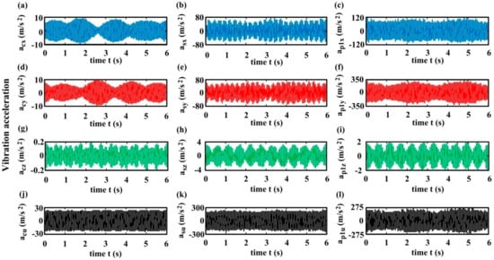
Figure 11.
Variations of the vibration accelerations of the main components from the model in the presence of the planet–gear eccentric error excitation Ep1 = 100 μm with gear mesh time. (a,d,g,j) the carrier accelerations in x-, y-, z-, and u-directions, represented as acx, acy, acz, and acu, respectively; (b,e,h,k) the sun accelerations in x-, y-, z-, and u-directions, represented as asx, asy, asz, and asu, respectively; (c,f,i,l) the planet accelerations in x-, y-, z-, and u-directions, represented as ap1x, ap1y, ap1z, and ap1u, respectively.
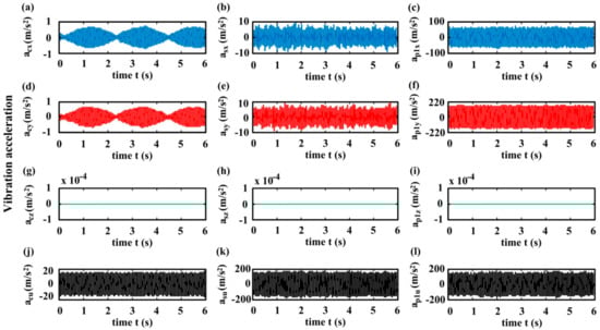
Figure 12.
Variations of the vibration accelerations of the main members from the model in the absence of error excitations with gear mesh time. (a,d,g,j) the carrier accelerations in x-, y-, z-, and u-directions, expressed as acx, acy, acz, and acu, respectively; (b,e,h,k) the sun accelerations in x-, y-, z-, and u-directions, expressed as asx, asy, asz, and asu, respectively; (c,f,i,l) the planet accelerations in x-, y-, z-, and u-directions, expressed as ap1x, ap1y, ap1z, and ap1u, respectively.
Figure 12 exhibits the variations of the accelerations for some main components of HPGT (i.e., the carrier, sun and planet) with gear mesh time (denoted as aix, aiy, aiz, aiu (i = c, s, p1), respectively), which reflect the vibrations of main system components containing the carrier, sun, and planet in the corresponding directions, respectively, for the case of the absence of manufacturing error excitations. A comparison of Figure 11a–c with Figure 12a–c indicates that in HPGT system, the vibration acceleration amplitudes in the x-direction of each component for the model without errors become evidently smaller than those for the model with the planet–gear eccentric error excitation, particularly the amplitude variation of vibration accelerations in the x-direction of the planet–gear is the most distinct in the two models with and without error excitations, on account of the planet eccentricity excitations. In the meantime, it is also seen that the vibration acceleration amplitudes in the y-direction of each member in the absence of error excitations displayed in Figure 12 are also noticeably smaller than those in the presence of the planet eccentricity excitation displayed in Figure 11, probably because of the planet–gear eccentricity excitation. The same tendency is also found for the vibration acceleration amplitudes in the u-direction (i.e., torsional direction) of each component. From Figure 11g,h,j and Figure 12g,h,j, it can be observed that for the model with the planet–gear eccentric error excitation, the vibration accelerations in the z-direction of the herringbone sun, herringbone planet, and carrier are small but nonzero; while for the model in the absence of error excitations, the z-direction vibration accelerations of the herringbone sun, planet, and carrier disappear, similar to the spur planetary gears. This means that manufacturing error excitations are the vibration source of the axial direction and directly impact the axial vibration of each member in the HPGT system.
Through comparing the results obtained from the model in the presence of the planet eccentricity shown in Figure 11 and those in the absence of the error shown in Figure 12, it is seen that manufacturing error excitations such as the planet eccentricity enhance the vibration acceleration responses in each DOF direction of each component in HPGT system, and the vibrations in the axial direction of HPGT are smaller and even vanishes similar to PGT with spur teeth when the planet–gear eccentricity is sufficiently small. In short, manufacturing error excitations such as the planet eccentricity increase the vibration acceleration responses of the herringbone planetary gears.
7. Conclusions
In this study, by considering the HPGT actual structure characteristics, manufacturing eccentric errors of components (i.e., each gear, and carrier), tooth profile errors of gears, gear tooth time-varying meshing stiffness and bearing deflections, different from the two-dimensional model, a novel and generalized three-dimensional lumped-parameter dynamic model of herringbone planetary gears has been given for studying the dynamic feature of the HPGT system in the presence of arbitrary number of planets and different types of manufacturing errors. The effects of manufacturing errors such as the planet eccentricity on the HPGT dynamic features were investigated. The main conclusions are given below.
- (1)
- Manufacturing errors such as the planet eccentricity prominently affect the HPGT dynamic features, and the manufacturing error excitations significantly increase the fluctuations of the dynamic meshing forces, dynamic bearing forces, and vibrations of components of herringbone planetary gears.
- (2)
- The fluctuations of the dynamic meshing forces and dynamic bearing forces for the model in the existence of the planet eccentricity excitation are evidently greater than those in the absence of error excitations. The amplitudes of vibration accelerations in each DOF direction of HPGT members for the model in the presence of the planet eccentricity excitation are also significantly larger than those in the absence of error excitations.
- (3)
- Manufacturing error excitations such as the planet eccentricity distinctly impact the axial vibrations of the carrier, sun, and planet of HPGT. Manufacturing error excitations are the axial vibration source in the HPGT system. For the model in the absence of error excitations, the axial forces and vibrations of the HPGT disappear, similar to spur PGT.
This investigation provides the new effective idea and methodology for the prediction and analysis of the dynamic feature of complex herringbone planetary gear systems with other type of error faults, and also offers the theoretical foundation for the error fault diagnosis and dynamic optimization of herringbone planetary gears in the next step. Our ongoing investigation will focus on the studies of the effects of system stiffness on herringbone planetary gear dynamic response.
Author Contributions
F.R. presented the HPGT system dynamic model, analyzed the results, and wrote this paper; A.L. analyzed some simulation results and reviewed the manuscript; G.S. modified the first draft of the manuscript and guided the contribution; X.W. revised the manuscript and gave some helpful and valuable suggestions; N.W. analyzed some simulation results. All authors have read and agreed to the published version of the manuscript.
Funding
This research was funded by the Science and Technology Research Project of Henan Province (Grant Nos. 202102210085, 172102210056), the Open Funding of Henan Key Laboratory of Intelligent Manufacturing of Mechanical Equipment (Grant No. IM201912), and the Doctoral Science Research Foundation of Zhengzhou University of Light Industry (Grant No. 2015BSJJ030).
Acknowledgments
The authors would like to express their gratitude to A/ Jinchen Ji in the University of Technology Sydney in Australia for helping modify the manuscript, especially polishing the language, and they are also very grateful to the editors and reviewers for their valuable comments and suggestions.
Conflicts of Interest
The authors declare no conflict of interest.
Abbreviations
| Nomenclature | |
| e | static transmission error |
| Ej | manufacturing eccentric error of the component (j = s, r1, r2, c, p1,…, pN) |
| Espi | tooth profile error in the ith sun-planet mesh (i = 1, 2,…, N) |
| Ij | moment of inertial of the component j (j = s, r1, r2, c, p1,…, pN) |
| F(t) | exciting force induced by the transmission error and time-varying mesh stiffness |
| G | gyroscopic matrix due to the rotation of the carrier |
| time-varying mesh stiffness of the right-side ith sun-planet mesh (i = 1, 2,…, N) | |
| time-varying mesh stiffness of the left-side ith sun-planet mesh (i = 1, 2,…, N) | |
| time-varying mesh stiffness of the right-side ith ring-planet mesh (i = 1, 2,…, N) | |
| time-varying mesh stiffness of the left-side ith ring-planet mesh (i = 1, 2,…, N) | |
| kj | bearing supporting stiffness of the component j (j = s, r1, r2, c, p1,…, pN) |
| kjt | tangential support stiffness of the component j (j = s, r1, r2, c) |
| Km, Kb | stiffness matrix related to gear mesh and bearing supporting |
| Kω | stiffness matrix related to the centrifugal effect of planets |
| mj | mass of the component j (j = s, r1, r2, c, p) |
| M | mass matrix of the whole system |
| N | number of planets |
| rj | base circle radius of the component j (j = s, r1, r2, p) |
| rc | radius of the circle passing through the planet centers |
| t | time |
| Tj | external torque acting on the component j (j = s, c) |
| T | external torque vector applied to the system |
| uj | torsional linear displacements of the component j (j = s, r1, r2, c, 1, …, N) |
| ωc | rational angular speed of the carrier |
| xi, yi | lateral translational displacements of the component j (j = s, r1, r2, c, 1, …, N) |
| U | system displacement vector |
| zi | axial motions of the component j (j = s, r1, r2, c, 1, …, N) |
| αt | transverse pressure angle |
| βb | base helix angle |
| planet assembly position angle | |
| relative mesh deflection of elastic elements used in the right-side and left-side sun-planet–gear mesh | |
| relative mesh deflection used in the ith ring-planet mesh spring for right and left ring gear | |
| relative deflections between the ith planet and the carrier in x-, y-, and z-direction of bearing spring | |
| Superscript | |
| L | left side |
| R | right side |
| Subscript | |
| c | carrier |
| s | sun gear |
| r | ring gear |
| r1, r2 | right and left ring gears |
| i | ith planet |
| p | planet–gear |
References
- Lin, J.; Parker, R.G. Planetary gear parametric instability caused by mesh stiffness variation. J. Sound Vib. 2002, 249, 129–145. [Google Scholar] [CrossRef]
- Lin, J.; Parker, R.G. Analytical characterization of the unique properties of planetary gear free vibration. J. Vib. Acoust. 1999, 121, 316–321. [Google Scholar] [CrossRef]
- Guo, Y.; Parker, R.G. Dynamic modeling and analysis of a spur planetary gear involving tooth wedging and bearing clearance nonlinearity. Eur. J. Mech. A-solid. 2010, 29, 1022–1033. [Google Scholar] [CrossRef]
- Zhao, M.; Ji, J. Nonlinear torsional vibrations of a wind turbine gearbox. Appl. Math. Model. 2015, 39, 4928–4950. [Google Scholar] [CrossRef]
- Kahraman, A. Planetary gear train dynamics. J. Mech. Des. 1994, 116, 713–720. [Google Scholar] [CrossRef]
- Tatar, A.; Schwingshackl, C.; Friswell, M. Dynamic behaviour of three-dimensional planetary geared rotor systems. Mech. Mach. Theory 2019, 134, 39–56. [Google Scholar] [CrossRef]
- Bu, Z.; Liu, G.; Wu, L. Modal analyses of herringbone planetary gear train with journal bearings. Mech. Mach. Theory 2012, 54, 99–115. [Google Scholar] [CrossRef]
- Sondkar, P.; Kahraman, A. A dynamic model of a double helical planetary gear set. Mech. Mach. Theory 2013, 70, 157–174. [Google Scholar] [CrossRef]
- Chaari, F.; Fakhfakh, T.; Hbaieb, R.; Louati, J.; Hadder, M. Influence of manufacturing errors on the dynamic behavior of planetary gears. Int. J. Adv. Manuf. Technol. 2006, 27, 738–746. [Google Scholar] [CrossRef]
- Xu, X.; Liu, H.; Ma, F.; Li, G. Load sharing research of planetary gear transmission system of wind turbine gearbox with flexible pins. J. Mech. Eng. 2014, 50, 43–49. [Google Scholar] [CrossRef]
- Ren, F.; Qin, D.; Lim, T.; Lyu, S. Study on dynamic characteristics and load sharing of a herringbone planetary gear with manufacturing errors. Int. J. Precis. Eng. Manuf. 2014, 15, 1925–1934. [Google Scholar] [CrossRef]
- Ren, F.; Luo, G.; Shi, G.; Wu, X.; Wang, N. Influence of manufacturing errors on dynamic floating characteristics for herringbone planetary gears. Nonlinear Dyn. 2018, 93, 361–372. [Google Scholar] [CrossRef]
- Ren, F.; Qin, D.; Wu, X. Load sharing performances of herringbone planetary gears considering manufacturing errors. J. Cent. South Univ. (Sci. Technol.) 2016, 47, 474–481. [Google Scholar]
- Qin, D.; Ren, F.; Wu, X. Effect of sun gear manufacturing eccentric errors on dynamic performances of herringbone planetary gear train. J. Northeast Univ. (Nat. Sci. Ed.) 2015, 36, 709–714. [Google Scholar]
- Zhu, Z.; Zhu, R.; Bao, H.; Jin, G. Impact of run-out and meshing-frequency errors on dynamic load sharing for encased differential herringbone train. J. Aerosp. Eng. 2011, 26, 2601–2609. [Google Scholar]
- Apuzzo, A.; Barretta, R.; Faghidian, S.A.; Luciano, R.; De Sciarra, F.M. Free vibrations of elastic beams by modified nonlocal strain gradient theory. Int. J. Eng. Sci. 2018, 133, 99–108. [Google Scholar] [CrossRef]
- Hu, J.; Mei, B.; Peng, H.; Jiang, X. Optimization design and analysis for a single motor hybrid powertrain configuration with dual planetary gears. Appl. Sci. 2019, 9, 707. [Google Scholar] [CrossRef]
- Zhang, R.; Xi, G.; Gu, F.; Wang, T.; Ball, A. Gear wear process monitoring using a sideband estimator based on modulation signal bispectrum. Appl. Sci. 2017, 7, 274. [Google Scholar] [CrossRef]
- Li, X.; Li, J.; Qu, Y.; He, D. Gear pitting fault diagnosis using integrated CNN and GRU network with both vibration and acoustic emission signals. Appl. Sci. 2019, 9, 768. [Google Scholar] [CrossRef]
- Lou, Z.; Xue, P.; Zheng, Y.; Fan, K. An analysis of angular indexing error of a gear measuring machine. Appl. Sci. 2018, 8, 169. [Google Scholar] [CrossRef]
- Faghidian, S.A.; Goudar, D.; Farrahi, G.H.; Smith, D.J. Measurement, analysis and reconstruction of residual stresses. J. Strain Anal. Eng. 2012, 47, 254–264. [Google Scholar] [CrossRef]
- Maatar, M.; Velex, P. An analytical expression for the time-varying contact length in perfect cylindrical gears: Some possible applications in gear dynamics. J. Mech. Des. 1996, 118, 586–589. [Google Scholar] [CrossRef]
© 2020 by the authors. Licensee MDPI, Basel, Switzerland. This article is an open access article distributed under the terms and conditions of the Creative Commons Attribution (CC BY) license (http://creativecommons.org/licenses/by/4.0/).