Abstract
The authors developed two types of block systems consisting only of main block and key block without joint mortar to improve the seismic performances and to enhance the workability. Two types of block systems have different key block shapes: one is the peanut shape, and the other is the dumbbell shape. The proposed block systems have a half-height difference between the main block and the key block to significantly improve seismic performance compared to typical masonry walls with joint mortar. In this study, in order to evaluate the in-plane seismic performance of the proposed block systems, two types of block walls are experimentally investigated, including the typical block wall. In the tests, three full-scale, single-story specimens are tested under in-plane cyclic loading, and failure patterns and cracks are carefully observed. In this paper, the in-plane loading bearing capacity, energy dissipate capacity and reuse ratios of block walls are discussed in detail. As a result, the deformability, energy absorption capacity and reuse ratio of the proposed block systems were considerably higher than those of a typical block system.
1. Introduction
Unreinforced masonry (URM) buildings are the most representative construction system since the early ages of mankind. Most of them are constructed without the consideration of earthquake design requirements or reference to any particular design code. It is common for the total or partial collapse of URM buildings to occur during an earthquake due to the poor quality of the materials and construction technology, as shown in Figure 1 and Figure 2, e.g., [1,2,3,4,5,6]. The low tensile strength, low ductility and low ability to dissipate energy are the main reasons for limiting the use of URM in middle- and high-seismicity regions. On the other hand, masonry has several advantages as a structural material, such as thermal and acoustic efficiency, economy, simple construction technology, excellent fire behavior and, usually, low embodied energy. Masonry has good durability and adequate performance with respect to healthy indoor environment, and can be effectively considered as an alternative low-cost construction solution for low- to medium-rise residential buildings.
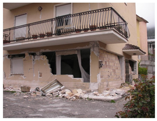
Figure 1.
Masonry wall damage of L’Aquila earthquake, Italy (2009).
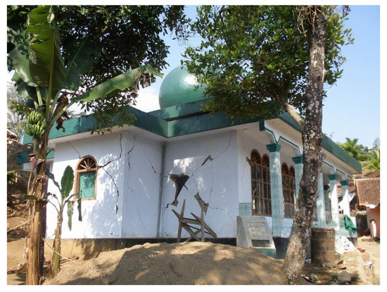
Figure 2.
Masonry wall damage of West Java earthquake, Indonesia (2009).
The increasing interest in this construction technique in the last few decades has resulted in many experimental tests on URM sub-assemblages [7,8,9,10,11] and on complete URM buildings [12,13,14,15,16,17,18]. These studies have provided significantly valuable insights into the seismic performance of URM buildings. However, many characteristics of URM buildings are yet to be fully understood, and URM buildings are always severely damaged when an earthquake occurs [13,14,16,17,18].
On the other hand, some studies on mortar-free masonry units considering the interlocking mechanism have been conducted, e.g., [19,20,21,22]. However, most of the studies are on brick units with unevenness, and there is no study targeting block units as in this study.
Under these backgrounds, the authors developed two types of new masonry wall systems for high seismic performance, including loading bearing capacity, deformability and energy dissipation capacity, convenience of construction and reliability of construction. The proposed masonry wall system only has a main block and a key block, without joint mortar. Two types of block systems have different key block shapes: one is the peanut shape, and the other is the dumbbell shape. It is expected that the proposed masonry wall system will be applied mainly to low-rise masonry houses, masonry fences and infilled masonry walls in developing countries.
In this study, the proposed two types of concrete block walls, as well as a typical concrete block wall, were experimentally investigated to evaluate their in-plane seismic performance. In the tests, full-scale, single-story specimens were tested under static cyclic in-plane loading, and failure patterns and cracks were carefully observed.
In this paper, the in-plane loading bearing capacity, energy dissipation capacity and reuse ratio of block walls are discussed in detail.
2. Outline of the Experiment
2.1. Proposed Block Systems
The authors developed two types of concrete blocks to improve the seismic performance of both in- and out-of-plane directions and to enhance the workability without the joint mortar [23]. The two types of concrete blocks only consist of main blocks and key blocks, and they have different key block shapes: one is the peanut shape and the other is the dumbbell shape, as shown in Figure 3.
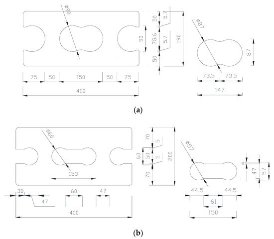
Figure 3.
Two types of concrete block systems (unit: mm): (a) Peanut shape concrete block; (b) Dumbbell shape concrete block.
Since the masonry unit may expand in the process of demolding and curing, a gap of 1.5 mm was inserted between the main block and the key block in consideration of these production errors, as shown in Figure 3. As can be seen in Figure 4 and Figure 5, the proposed block systems have a half-height difference between the main block and the key block. The main blocks on both sides of the wall have half-sized key blocks, as shown in Figure 5. Although the behavior of the masonry wall in the in-plane direction and the out-of-plane direction are different, a high seismic performance in both directions can be expected because of the height difference forms in the interlocking mechanism.
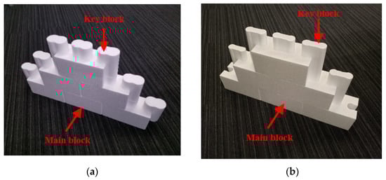
Figure 4.
Construction of the proposed block walls: (a) Peanut shape; (b) Dumbbell shape.
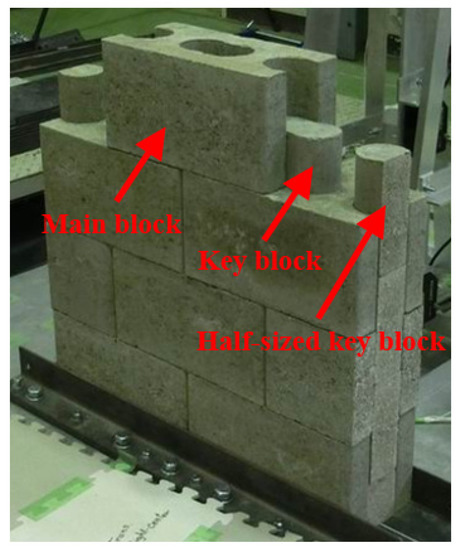
Figure 5.
Construction of the peanut-shaped concrete block wall.
2.2. Material Characteristics
Each concrete block’s material test results are shown in Table 1 (the average values of three samples are shown in the table). The typical concrete block and peanut-shaped concrete block were made with the normal cement-to-sand ratio of 1:3 used in Korea. However, since the dumbbell-shaped concrete block has a higher cement ratio, the compressive strength is the highest value among the three concrete blocks, as shown in Table 1. The typical concrete block has three hollows inside and a half-sized hollow on both ends. On the other hand, the peanut-shaped concrete block has the key blocks in hollow parts of the main block. Therefore, the compressive strength of the peanut-shaped concrete block is higher than that of the typical concrete block, because it is divided by the whole area, including the hollow parts (=390 mm × 190 mm), and not the net area excluding the hollow parts, as shown in Table 1. The weights of the typical concrete block, the peanut-shaped concrete block and the dumbbell-shaped concrete block including the key blocks are 0.2, 0.3 and 0.36 kN, respectively.

Table 1.
Mechanical properties of each concrete block.
2.3. Test Specimens
In this study, three full-scale, single-story specimens were designed and fabricated supposing a single-story storage building: (1) typical concrete block wall specimen with joint mortar (Specimen CB); (2) seismic block wall with a peanut-shaped key block without joint mortar (Specimen PS); (3) seismic block wall with a dumbbell-shaped key block without joint mortar (Specimen DS). The specimen’s size is 2.0 m by 1.4 m, as shown in Figure 6. The joint mortar with the cement-to-sand-to-water ratio of 1:3:0.5 is placed horizontally and vertically between the concrete block units. The average compressive strength of the joint mortar is 32 N/mm2.
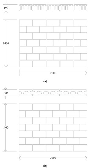
Figure 6.
Details of typical and proposed concrete block wall specimens (unit: mm): (a) Specimen CB; (b) Specimen PS.
The typical concrete block wall can resist only the friction force to the horizontal load after losing the adhesive force between the concrete block and the joint mortar. On the other hand, the proposed concrete block wall systems can expect a higher deformability due to the interlocking mechanism between the main blocks and the key blocks.
2.4. Test Program
A loading system for the static cyclic in-plane tests is shown in Figure 7. Lateral loads in the positive and negative directions were applied to the left end of the upper beam with hydraulic actuators. As mentioned above, since the reference building of this study is a single-story storage building, the axial load was considered as the weight of the upper beam (13.7 kN, axial stress, σ0 = 0.04 N/mm2). Figure 8 shows a lateral loading protocol that was controlled by a drift angle R, defined as a lateral drift Δ at the top-center of the specimen divided by the height from the bottom of the specimen, H, as shown in Figure 7. As shown in Figure 8, the peak drift angles of 0.0005, 0.001, 0.002, 0.004, 0.0067, 0.01, 0.015, 0.02, 0.03, 0.04 and 0.05 rad., that is, 0.05, 0.1, 0.2, 0.4, 0.67, 1.0, 1.5, 2.0, 3.0, 4.0 and 5.0% rad., were planned, and two cycles for each peak drift were imposed. After severe damage was found, the specimen was pushed over to collapse.
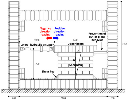
Figure 7.
Loading system (unit: mm).
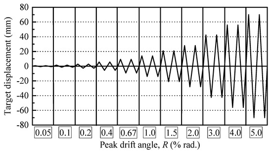
Figure 8.
Lateral loading protocol.
The measurement system is shown in Figure 9. As shown in Figure 9, 14 displacement transducers were used: one relative lateral displacement transducer, five lateral displacement transducers at each layer of wall, two vertical displacement transducers of both ends of the specimen, four sliding displacement transducers of both ends of the top and bottom, and two diagonal deformation transducers of the wall. The 3-axis strain gauges for calculation of the principal strain were attached on all blocks of the only Specimen PS, but the strain data were not measured because of the trouble of the measuring equipment. Furthermore, the maximum crack widths at peak loads and residual crack widths at unloaded stages were carefully measured.
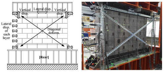
Figure 9.
Measurement system.
3. Experimental Results
3.1. Failure Patterns and Lateral Force—Drift Angle Relationships
Figure 10 and Figure 11 show the damage patterns after final loading and the lateral force–drift angle relationships of all specimens, respectively. The behavior of each specimen to failure is summarized below.
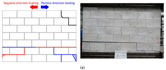
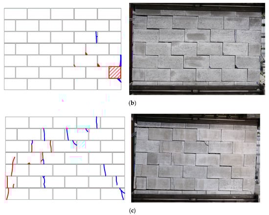
Figure 10.
Final crack patterns (blue line: Positive direction loading, red line: Negative direction loading, black line: initial cracks, hatched: crushing): (a) Specimen CB; (b) Specimen PS; (c) Specimen DS.
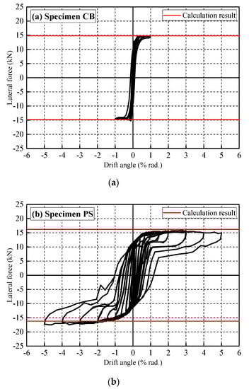
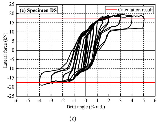
Figure 11.
Lateral force - drift angle relationships of each specimen: (a) Specimen CB; (b) Specimen PS; (c) Specimen DS.
3.1.1. Specimen CB
During the first loading drift, R, of 0.05% rad., the cracks were observed in the entire bed joint (horizontal joint), causing slippage between the second and third joint interfaces. Since the shear crack in the bottom of the compression side occurred during R = 0.67% rad. and the crushing in the bottom of the compression side occurred during R = 1.0% rad., as shown in Figure 10a, the test was terminated at R = 1.0% rad. Until the final loading, this specimen showed a rocking behavior between the second and third layers. The maximum strength of 14.7 kN was recorded at R = 0.67% rad., and no remarkable strength deterioration was found until R = 1.0% rad.
3.1.2. Specimen PS
The small width crack occurred on the main block of the right-bottom end at R = 0.25% rad. This specimen also showed a rocking behavior until the final loading because of the low axial force according to the single-story storage building. Since the crushing and spalling off of the main block at the rightmost side of the second layer occurred at R = −5.0% rad., the experiment was terminated after R = 5.0% rad. The maximum strength of −17.5 kN was recorded at R = −2.0% rad., and no remarkable strength deterioration was found until the final loading.
3.1.3. Specimen DS
This specimen had more vertical cracks on the main blocks than Specimen PS. The small width cracks occurred on the main blocks of both bottom ends at R = 0.1% rad. This specimen also showed a rocking behavior. Since the crushing and spalling off of the main block at both ends of the second layer occurred at R = 5.0% rad., the experiment was terminated after R = 5.0% rad. The maximum strength of 19.7 kN was recorded at R = 3.0% rad., and no remarkable strength deterioration was found until the final loading.
3.2. Comparison of the In-Plane Seismic Performance of Each Specimen
3.2.1. Lateral Force—Drift Angle Relationships
Figure 12 shows the backbone curves of each specimen. For the backbone curves, the values of the new first loading drift angle were adopted. As shown in Figure 12, the in-plane seismic performances of Specimens PS and DS were much higher than that of Specimen CB. In particular, the deformability of the proposed system improved remarkably due to the interlocking mechanism between the main blocks and the key blocks.
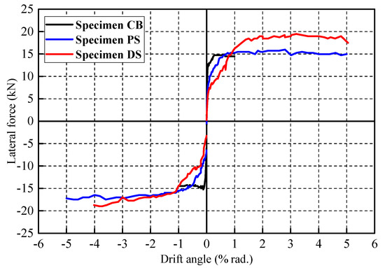
Figure 12.
Backbone curves of each specimen.
In this study, the additional simple monotonic loading tests were carried out for verifying the rocking behavior, as shown in Figure 13. The three-layered specimens with typical, peanut-shaped and dumbbell-shaped concrete blocks, respectively, were used in the tests. As shown in Figure 14, the axial loads were considered as the sum of the weight of the upper loading beam (N1 = 3.7 kN) and the self-weight of the specimen (N2 = 0.4 kN, 0.6 kN and 0.72 kN of typical, peanut- and dumbbell-shaped three-layered specimens, respectively). The calculated lateral loads are shown in Figure 15, with the test results. As can be seen in the figure, the calculated lateral loads agreed well with the experimental results. Among the test results, the increased lateral force of the typical block specimen may result from the adhesive force by the joint mortar.
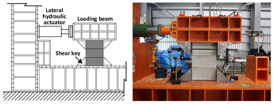
Figure 13.
Loading system for verifying rocking behavior.
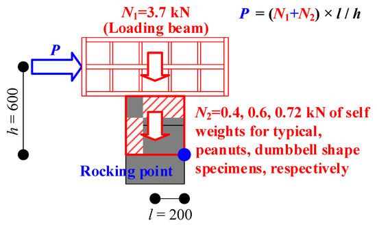
Figure 14.
Lateral load P due to rocking behavior.
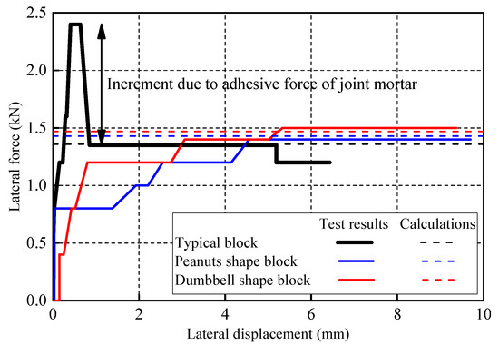
Figure 15.
Monotonic loading tests vs. calculation results.
The lateral loads of Specimens CB, PS and DS were calculated in the same manner, as mentioned above. Figure 16 shows the rocking mechanism of Specimens CB, PS and DS. As can be seen in the figure, the axial loads were considered as the sum of the weight of the upper beam (N1 = 13.7 kN) and the self-weight of the specimen (N2 = 6.0 kN, 9.0 kN and 10.8 kN of Specimens CB, PS and DS, respectively). The calculated lateral loads were shown in Figure 11. As shown in the figure, the calculated lateral loads exhibit a good agreement with the experimental results.
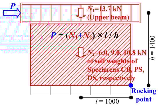
Figure 16.
Lateral load p due to the rocking mechanism.
3.2.2. Equivalent Viscous Damping Ratios
In order to compare the energy dissipation capacities of all specimens, the equivalent viscous damping ratios were calculated, as shown in Figure 17. As shown in Figure 18, the values of the proposed systems were distributed higher than those of Specimen CB because friction force was generated between the main block and the key block of the proposed systems, as shown in Figure 10. Furthermore, the remarkable deterioration of the ratios of the proposed systems were not found until the final loading. As shown in the Figure 10, Figure 11, Figure 12 and Figure 18, the gap of 1.5 mm between the main block and the key block did not adversely affect the in-plane seismic performance. However, the gap size has to be judged or modified comprehensively, including the results of out-of-plane shaking table experiments.
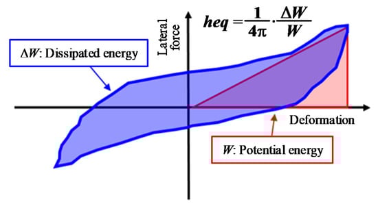
Figure 17.
Equivalent viscous damping ratios of each specimen.
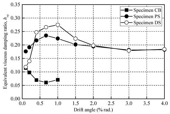
Figure 18.
Equivalent viscous damping ratios of each specimen.
3.2.3. Reuse Ratios of Specimens PS and DS
The typical concrete block and cement brick are generally not reusable because of the joint mortar. On the other hand, the proposed systems consisted of only main and key blocks without joint mortar can reuse. In this study, the reuse ratio is defined as the ratio of no damage main blocks to all main blocks. Figure 19 shows the reuse ratio of Specimens PS and DS. As can be found in the figure, the proposed seismic block systems can reuse more than 70% after R = 5.0% rad. This result implies that the proposed concrete block wall systems are economical and eco-friendly.
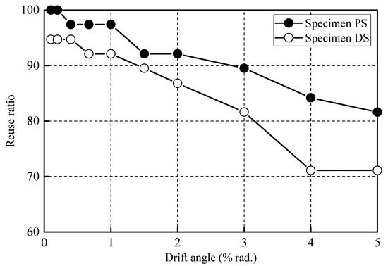
Figure 19.
Monotonic loading tests vs. calculation results.
4. Conclusions
The current paper presented the experimental tests of two types of new concrete block walls as well as a typical block wall and investigated their in-plane behavior, loading bearing capacity, energy dissipation capacity and reuse ratio. The following major findings were obtained:
- [1]
- The in-plane seismic performances of Specimens PS and DS were much higher than that of Specimen CB. In particular, the deformability of the proposed system has improved remarkably due to the interlocking mechanism between the main blocks and the key blocks.
- [2]
- The calculated lateral loads based on the simple rocking mechanism agreed well with the experimental results.
- [3]
- The energy dissipation capacities of the proposed systems were considerably superior to that of Specimen CB. Furthermore, the remarkable deterioration of the ratios of the proposed systems were not found until the final loading.
- [4]
- The proposed seismic block systems can reuse more than 70% after the final loading. This result implies that the proposed concrete block wall systems are economical and eco-friendly.
The current paper focused only on the in-plane experimental behavior. If the proposed system is established as one of the masonry systems in the future, it will improve the seismic performance, convenience of construction and reliability of construction, and thus the earthquake damage of masonry buildings will be reduced. Although the gap of 1.5 mm between the main block and the key block did not adversely affect the in-plane seismic performance, its size needs to be comprehensively examined, including the results of out-of-plane shaking table experiments. For these purposes, the experimental data should be investigated from numerical perspectives, and the out-of-plane experimental and numerical behaviors should be carried out in future studies.
Author Contributions
All authors have contributed to the development of the research and in the elaboration of this article. Particularly, H.C. contributed to the methodology and the experimental research, and K.-S.L. contributed the methodology and edited the manuscript. All authors have read and agreed to the published version of the manuscript.
Funding
This research received no external funding.
Acknowledgments
This research was supported by a grant (2020-MOIS31-012) of the Fundamental Technology Development program for Extreme Disaster Response, funded by Ministry of Interior and Safety (MOIS, Korea).
Conflicts of Interest
The authors declare no competing interests.
Data
All datasets generated in this study are available from the corresponding author upon reasonable request.
References
- Abrams, D.P.; Shah, N. Cyclic Load Testing of Unreinforced Masonry Walls; Advanced Construction Technology Centre Report No. 92-26-10; University of Illinois at Urbana Champaign: Champaign, IL, USA, 1992. [Google Scholar]
- Magenes, G.; Calvi, G.M. Shaking Table Tests on Brick Masonry Walls. Proceedings of 10th European Conference on Earthquake Engineering 1995, Vienna, Austria, 28 August–2 September 1995; pp. 2419–2424. [Google Scholar]
- Doherty, K.T. An Investigation of the Weak Links in the Seismic Load Path of Unreinforced Masonry Buildings. Ph.D. Thesis, Faculty of Engineering, University of Adelaide, Adelaide, Australia, 2000. [Google Scholar]
- Griffith, M.C.; Vaculik, J.; Lam, T.K.; Wilson, J.; Lumntarna, E. Cyclic Testing of Unreinforced Walls in Two-way Bending. Earthq. Eng. Struct. Dyn. 2006, 36, 801–821. [Google Scholar] [CrossRef]
- Simsir, C.; Aschheim, M.; Abrams, D. Influence of Diaphragm Flexibility on the Out-of-plane Response of Unreinforced Masonry Bearing Walls. In Proceedings of the 9th North American Masonry Conference 2002, Clemson, SC, USA, 28 February 2002. [Google Scholar]
- Tomazevic, M. Dynamic Modelling of Masonry Buildings: Storey Mechanism as a Simple Alternative. Earthq. Eng. Struct. Dyn. 1987, 15, 731–749. [Google Scholar] [CrossRef]
- Qamaruddin, M.; Chandra, B. Behaviour of Unreinforced Masonry Buildings Subjected to Earthquakes. Prof. J. Mason. Soc. USA 1991, 9, 47–55. [Google Scholar]
- Calvi, G.M.; Pavese, A. Application of Dynamic Identification Techniques to a Brick Masonry Building Prototype. In Proceedings of the 10th European Conference on Earthquake Engineering 1995, Vienna, Austria, 28 August–2 September 1995; pp. 2413–2418. [Google Scholar]
- Tomazevic, M. Seismic Upgrading of Old Brick-Masonry Urban Houses: Tying of Walls with Steel Ties. Earthq. Spectra 1996, 12, 599–622. [Google Scholar] [CrossRef]
- Costley, A.C.; Abrams, S.P. Dynamic Response of Unreinforced Masonry Buildings with Flexible Diaphragm; Technical Report No. MCEER-96-0001; MCEER: Washington, DC, USA, 1996. [Google Scholar]
- Benedetti, D.; Carydis, P.; Pezzoli, P. Shaking Table Test on 24 Masonry Buildings. Earthq. Eng. Struct. Dyn. 1998, 27, 67–90. [Google Scholar] [CrossRef]
- Yi, T.; Moon, F.L.; Leon, R.T.; Kahn, L.F. Lateral Load Tests on a Two-story Unreinforced Masonry Building. ASCE J. Struct. Eng. 2006, 132, 643–652. [Google Scholar] [CrossRef]
- Architectural Institute of Japan (AIJ). Report on the Damage Investigation of the 1999 Chi-Chi Earthquake; Architectural Institute of Japan: Tokyo, Japan, 2000. [Google Scholar]
- Architectural Institute of Japan (AIJ). Report on the Damage Investigation of the 2006 Central Java Earthquake; Architectural Institute of Japan: Tokyo, Japan, 2007. [Google Scholar]
- Manafpour, A.R. Bam Earthquake, Iran: Lessons on the Seismic Behavior of Building Structures. In Proceedings of the 14th World Conference on Earthquake Engineering, Beijing, China, 12–17 October 2008. [Google Scholar]
- Sanada, Y.; Kishimoto, I.; Kuroki, M.; Sakashita, M.; Choi, H.; Tani, M.; Hosono, Y.; Fauzan, M.S.; Farida, F. Preliminary Report on Damage to Buildings due to the September 2 and 30, 2009 Earthquakes in Indonesia. In Proceedings of the Eleventh Taiwan-Korea-Japan Joint Seminar on Earthquake Engineering for Building Structures, Kyoto, Japan, 2–3 November 2009; pp. 297–306. [Google Scholar]
- Choi, H.; Sanada, Y.; Kuroki, M.; Sakashita, M.; Tani, M.; Hosono, Y.; Musalamah, S.; Farida, F. Comparing Damage to Building Structures Due to the 2009 West Java Earthquake in Indonesia. In Proceedings of the 2nd International Conference on Earthquake Engineering and Disaster Mitigation, Surabaya, Indonesia, 19–20 July 2011. [Google Scholar]
- Architectural Institute of Japan (AIJ). Reconnaissance Report on the 2015 Nepal Gorkha Earthquake; Architectural Institute of Japan: Tokyo, Japan, 2016. [Google Scholar]
- Amin, A.; Bashar, S.M.; Fadhil, N.; Ehsan, N. Development of Interlocking Masonry Bricks and its’ Structural Behaviour: A Review Paper. IOP Conf. Ser. Earth Environ. Sci. 2018, 140, 012127. [Google Scholar]
- Hossain, M.A.; Totoev, Y.Z.; Masia, M.J. Experimental assessment of large displacement cyclic in-plane shear behaviour of semi-interlocking masonry panels. Int. J. Mason. Res. Innov. 2019, 4, 378–399. [Google Scholar] [CrossRef]
- Liu, H.; Liu, P.; Lin, K.; Zhao, S. Cyclic Behavior of Mortarless Brick Joints with Different Interlocking Shapes. Materials 2016, 9, 166. [Google Scholar] [CrossRef] [PubMed]
- Majid, A.; Romain, B.; Nawawi, C. Dynamic response of mortar-free interlocking structures. Constr. Build. Mater. 2013, 42, 168–189. [Google Scholar]
- Choi, H.; Jin, K.W.; Jeong, J.C.; Kim, B.S.; Hwang, E.J.; Jin, C. Feasibility Study on Seismic Block without Joint Mortar, Part1 Shape Determination Using Finite Element Analysis, Summaries of Technical Papers of Annual Meeting; Architectural Institute of Japan: Tokyo, Japan, 2019; Volume 4, pp. 977–978. [Google Scholar]
Publisher’s Note: MDPI stays neutral with regard to jurisdictional claims in published maps and institutional affiliations. |
© 2020 by the authors. Licensee MDPI, Basel, Switzerland. This article is an open access article distributed under the terms and conditions of the Creative Commons Attribution (CC BY) license (http://creativecommons.org/licenses/by/4.0/).