Abstract
This study proposed a calligraphy brush trajectory model for the behavior of brush movements and provided the three-dimensional handle coordinates for a robotic arm to write calligraphy. This study dealt with basic footprints and bent lines of calligraphy and proceeded as follows. The shape of brush footprints on paper was measured, which provided the positions of the brush relative to its handle. These brush footprints were scanned and corrected for skew using the Direct Linear Transformation. The outer frame of each basic footprint was characterized using Bézier curves. Bent lines were drawn to derive the brush trajectory model, and it was used to derive the relationship between the trajectories of the brush and handle. By characterizing the changes in the footprints with handle displacement, we obtained the relationship between the handle coordinates and the position and shape of the brush footprints. The written characters were evaluated based on their size, position, and stroke balance, with a maximum score of 100 in each category. The average score of the “Yong” character written using our brush trajectory model was approximately 94 points; when the handle coordinates were fixed to the center of each footprint, the average score was only 88 points.
1. Introduction
Chinese calligraphy is generally taught and learned by the lintie or motie approaches. In the lintie approach, a copybook is placed on the side, and the learner imitates the characters in the copybook. In the motie approach, the copybook is placed under a sheet of paper, and the learner learns how to write by “filling” the shape of the word on said sheet of paper. In this work, we will employ a motie-like approach. First, the character models are digitalized and binarized, and the brush’s trajectory are then manually drawn up according to these models. We then converted the coordinates of this trajectory into handle coordinates according to the footprints’ sizes, which are then transferred to the robotic arm. The aim of this study is to imitate copybook models and allow the users of this system to write arbitrary Chinese characters using a robotic arm. This system can be used to aid teaching of calligraphy.
When writing calligraphy, the brush tip will first be moved to a position where it first makes contact with the paper, and then the handle of the brush pen will be moved. Finally, the handle will be raised so that the tip leaves the paper, thus completing a stroke. Chinese characters are formed either by one stroke or a combination of strokes. To facilitate the subsequent discussions in this paper, we have defined six terms based on information about the processes of calligraphy writing:
- Anbi: The pen is moved straight down so that the tip just touches the paper.
- Dunbi: The pen is pressed downwards and then made to move horizontally.
- Tibi: The pen is moved upwards and then made to move horizontally.
- Xingbi: The pen is made to move horizontally while being fixed at a certain height.
- Shoubi: The pen is moved vertically upwards so that the tip leaves the paper.
- Yunbi: The process in which a stroke is written (Anbi → (dunbi, xingbi, tibi) → Shoubi).
The characteristics of every brush are different. For example, brushes with different cross-sectional diameters and lengths will produce different footprint widths, even with the same handle height. The elasticity coefficient of a brush also depends on the material it is made from, and this will cause the curvature of the brush’s spine to vary from one brush to another. Consequently, the position of the footprints produced by each brush will differ. Furthermore, if the maximum ink content of the brush is different, the “dryness” and “wetness” of each stroke will also differ. There are then eight variables that must be defined for each brush: the brush’s length, maximum diameter, elasticity coefficient, ink content, and friction against paper [1,2,3,4], as well as the handle’s slope [2,5], speed of motion [2,4], and turning angle [2,4]. Although some of these variables can be measured (like the diameter and length of the brush) or estimated via indirect methods (e.g., the elasticity coefficient of the brush), troublingly, there are a few variables that must be assumed (e.g., maximum ink content).
In the past, studies about the computerization of Chinese calligraphy generally employed one of two approaches: the characters were either displayed on a digital display, or written by a robotic arm. Some of the studies that employed the first approach are described below. Miura et al. [6] used a haptic interface to control a brush in a motion-reproduction system. Then a robot reproduced the taught motion to write calligraphy. Baxter et al. [1] also used a haptic interface to control a virtual brush, which models the bristles of the brush with a spring-mass particle system skeleton and a subdivision surface, thus allowing the brush to deform upon contact with the paper. The virtual brush could then be controlled in an intuitive manner, which makes it easy for an artist to paint or write on a digital display.
In [7], the brush’s spine was modeled as a connected sequence of line segments to simulate the brush’s deformations, and the cross-section of the brush was approximated by an ellipse. Furthermore, the brush’s deformations were modeled by constrained energy minimization, with the cross-sectional area of the brush being an invariant. Their 3D brush model also mimics the spread of ink. In this way, they were able to produce 3D calligraphy that strongly resembles real calligraphy. In [2], the brush’s pressure on paper was used to estimate the relative motions of the brush’s handle and tip. The parameters that affect brush pressure were also given in this work, and they include the curvature of the brush’s spine, the brush’s velocity, the angle between brush direction and curvature, brush elasticity, and the paper’s roughness. However, other than the speed of the brush, all of these parameters are difficult to measure.
In [8], each Chinese character was systematically decomposed into six layers (layers 0–5), which makes it easier to analyze and segment Chinese characters; this is especially useful for writing in regular script. In this method, constructive ellipses were used to construct the zeroth layer. The trajectory taken by the brush’s tip varies with that of its handle, and the movements taken by the tip will gradually become the same as those of the handle. In [9], the angle of the next brush tip position was obtained by averaging the angles between the movement of the brush’s handle and current position of the brush’s tip, and the rotational center of the brush footprint’s tip was always kept inside the brush footprint. In [3], the deformations of the brush’s spine were modeled by a computer, and the authors used the “equilibrium bend energy” to calculate the relative positions of the brush’s tip and handle when the brush pen was moving.
Some researchers have also proposed methods where the shape or trajectory of the brush footprints are measured directly instead of being simulated by computational means. For example, Okabe et al. [10] constructed an apparatus to directly capture brush footprints using a camera; the features of the brush footprints were then extracted to train a Hidden Markov Model (HMM). In [5], each basic brush footprint was represented by eight sampling points, and their shape was approximated by a droplet-like shape. The outer frame of each footprint (which includes the footprint’s width) was described by the inclination and height of the handle, and basic strokes were formed by searching for a suitable set of continuous basic footprints based on stroke width.
Numerous studies have also been performed on robotic calligraphy. For example, Mueller et al. [11] made a robotic arm write calligraphy by sending the 3D coordinates of continuous basic footprints to the robotic arm. A camera was then used to photograph the drawing area and the saved images were then compared to a reference image to determine the corrections required by the brush footprints; the coordinates of the brush footprints were thus iteratively corrected until the strokes drawn by the robotic arm resembled those of the model character. In [4], the Learning from Demonstration (LfD) method was used to transfer human calligraphy skills to a robotic arm. Each stroke was represented by five parameters, and these parameters were used as inputs for their learning algorithm, whose outputs are the coordinates and orientations of the end-effector (brush tip). In this method, the stroke parameters are supplied to the system, and a likelihood function is used to search for the most probable outputs; after the trajectories of every joint have been solved via inverse kinematics, the robotic arm is then able to write new strokes. Ma and Su [12] extracted calligraphic features like the position, width, length, inclination, and center of gravity of each stroke, and then passed these parameters to a robotic arm to make it write calligraphy. A camera was then used to photograph the resulting brush strokes, which were fed back to an aesthetics evaluation mechanism to adjust the robotic arm’s parameters. This mechanism used coordination, balance, and distribution indices to evaluate the aesthetics of each stroke. In [13], it was observed that the positions of a brush’s handle and footprint are different. To measure the relationship between these variables, a robotic arm was used to draw lines and arcs using a hairy brush. The authors then measured brush lag and the relationship between Z-axis depth and footprint width.
The novelty of this work lies in our use of basic brush footprint measurements, like in [5,10,13], and a droplet-like shape to approximate the outer frame of brush footprints, to perform robotic calligraphy. A robotic arm was used to precisely draw basic footprints, which are then scanned. The scanned images were corrected for skew using the direct linear transformation (DLT), and the outer frame of the basic footprints was represented by Bézier curves. The footprints produced by making the handle move in a bent trajectory were then used to measure the relative positions of the handle and brush tip. Based on these procedures, we were able to obtain the footprints that correspond to the handle’s movements. This approach forgoes the need for additional equipment to measure the brush pen’s position and footprints (like in [7,10]), and it also sidesteps the need to consider the variations in the brush’s spine (like in [3]). The quality of the characters written by the robotic arm was evaluated using the scoring algorithm provided by [14], and these characters were also compared to model characters in terms of their size, position, and stroke balance. Finally, the similarity between the written and model characters was calculated.
The contents of each section are as follows. Section 2 describes the problem addressed by this study and the architecture of our system, while Section 3 describes the methods proposed in this paper, including the method for extracting the parameters of the brush footprints and the brush trajectory model. Section 4 describes the experimental results of this work, and Section 5 provides a discussion on these results and the conclusion of this paper.
2. Problem Description and System Architecture
2.1. Problem Description
During the writing of each stroke, the brush tip will touch or leave the paper, and the brush’s spine will also tilt to a side, which results in a gap between the handle and brush, as shown in Figure 1a. This is the so-called “footprint lag”, which is defined in Figure 1b. Figure 1b also shows that the footprint left by the brush on the paper resembles a water droplet in shape. Figure 1a has a 3D coordinate system, and the brush is assumed to move along the X-axis, whereas Figure 1b has a 2D coordinate system that exists on a horizontal plane (the paper). The mapping between the location terms in Figure 1a,b is shown in Table 1.
Figure 1.
Relationship between handle position, the brush’s curvature and the brush footprint. (a) The curvature of the spin causes the projection of the handle’s base to be different from the brush footprint. (b) The footprint left by the brush on the paper.
Table 1.
Mapping between the location terms for the handle/brush and footprint.
As calligraphy strokes are assumed to consist of trajectories traversed by droplet-shaped footprints, each trajectory can be decomposed into a series of droplet-shaped footprints, as shown in Figure 2a. The greyed areas of this figure are the model character. For purposes of clarity, only a few representative droplet-shaped footprints are shown in Figure 2b. In Figure 1b, it is shown that there is a lag between the footprints and handle base, like in the shu (vertical) stroke shown in Figure 2b. Figure 3 shows the handle positions of each footprint, which are represented by small circles in this figure.
Figure 2.
Calligraphy strokes represented by droplet-shaped footprints. (a) Calligraphy strokes represented by a series of droplet-shaped footprints. (b) Calligraphy strokes represented by a few representative droplet-shaped footprints.
Figure 3.
Droplet-shaped footprints and their corresponding handle positions.
As the robotic arm only has direct control over the handle and not the position of the brush on the paper (i.e., the footprints), the footprint’s size, lag, and angle () will vary with the handle’s coordinates (Figure 4). In this paper, we used the footprint’s size, lag, and angle () as the factors of the brush trajectory model and studied whether the brush’s handle had a relationship with these factors. If there existed the relationship, we were able to use the brush’s handle to control the brush trajectory. Since this work was an experimental study to show whether the brush’s handle position was possible to control the brush trajectory, we did not further explore the control principles in different brush pens. To obtain the relationship between the positions of the brush’s handle and footprints, the robotic arm was made to draw a few basic footprints by sending known handle coordinates to the robotic arm. A set of images where the footprints’ outer frames and positions may be measured was thus produced. By analyzing these images, we obtained a mechanism that allows the robotic arm to write calligraphy by receiving handle coordinates, i.e., the “brush trajectory model” (Figure 5a). Figure 5b illustrates the process by which the brush trajectory model was used to guide users in finding a suitable set of handle coordinates to write a complete character using the robotic arm.
Figure 4.
Positional relationship between a brush’s base and its footprint.
Figure 5.
Brush trajectory model. (a) Obtaining the brush trajectory model from experimental measurements. (b) Using the brush trajectory model to obtain the outer frames and positions of the brush footprints.
The outer frame, lag, and of the footprints are the three factors that make up the brush trajectory model. The aim of this study is to analyze these factors (with the guidance of a model character) to find a set of handle coordinates that will allow the footprints’ trajectory to resemble the model character. The robotic arm will then write calligraphy using these coordinates.
We are only able to control the trajectory of the handle, but the strokes are produced by the brush’s trajectory rather than that of the handle. Furthermore, the handle and brush trajectories cannot overlap with each other, unless the brush tip is made to stay in contact with the paper at all times. However, this would eliminate all variations in stroke fineness, which are crucial for aesthetic quality. Therefore, we have divided this problem into two sub-problems: the first problem pertains to the shape of the brush area that is in contact with the paper when the handle is pressed downwards, and the second problem is about the movement of the brush when the handle is moved. The outer frames of the basic footprints will be obtained by measuring the footprints, and the footprints and handle coordinates are then selected to produce the appropriate stroke width. These 3D coordinates are then transferred to the robotic arm to make it write the desired Chinese character.
2.2. System Architecture
The process flow diagram by which our system writes calligraphy using a brush pen is shown in Figure 6. As the robotic arm can only control the position of handle’s base, we have decomposed the brush trajectories into line segments, to simplify the problem of brush deformations. The brush is assumed to be a “time invariant” device, and the handle is always perpendicular to the paper during the writing process. We then estimated the outer frames and trajectories of the footprints by using measurements of the footprints’ outer frames in conjunction with the brush trajectory model. The process for producing the 3D handle coordinates is as follows:
Figure 6.
Process flow for writing calligraphy using our system.
3. The Proposed Method
3.1. Extracting the Parameters of Basic Footprints
3.1.1. Direct Linear Transformation (DLT)
In robotic calligraphy, the handle’s movements and changes in height will alter the shape of the footprint. Therefore, the brush footprints were scanned into images. The images were corrected for skew using the Direct Linear Transformation (DLT), which also ensures that all of the model character images and calligraphy scans are the same size (2000 × 2000 pixels). The derivation of the DLT is shown below:
Let (u, v) and (x, y) be the raw and corrected image coordinates, respectively. These coordinates are related by
By using four reference points, (, ), (, ), (, ), and (, ) and their corresponding (, ), (, ), (, ), and (, ) coordinates, the eight unknowns in Equation (1), –, may then be solved, which gives the relationship between (u, v) and (x, y).
DLT was used to correct the skew in the scanned images. To perform the DLT, there must be four corresponding reference points in the raw image coordinates and corrected image coordinates. The raw image coordinates are (, ), (, ), (, ) and (, ), which correspond to (, ), (, ), (, ) and (, ) in the corrected image. As these image coordinates must be selected manually, the corrected image will be distorted in various ways if mistakes were made during the selection of these coordinates.
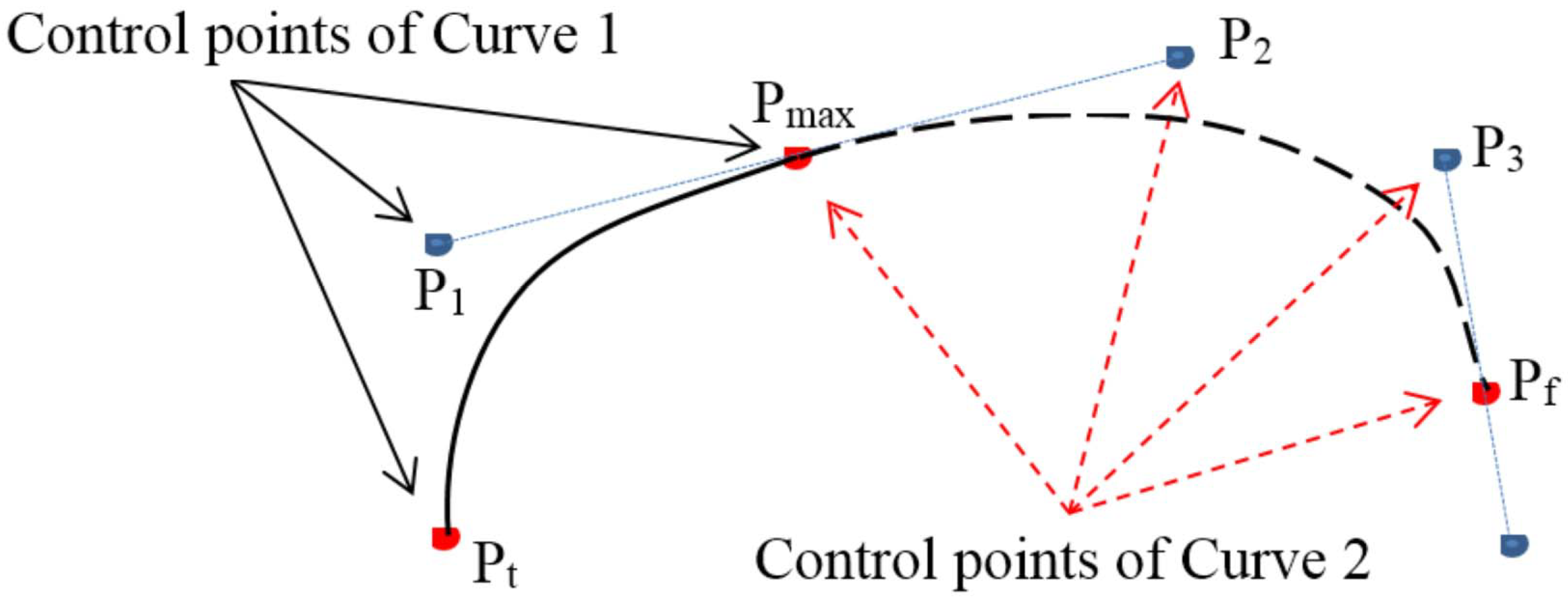
3.1.2. Describing the Basic Footprints’ Outer Frames Using Bézier Curves
As Bézier curves can be used to link discrete points by a smooth line, this approach can be used to describe the outer frame of each basic footprint. If the Bézier curve lies on an XY-plane, the parametric equation for the Bézier curves may be formulated as
where are the control points.
The outer frame of each basic footprint was divided into four Bézier curves. The four sampling points (see Figure 7) are the tip of the footprint ( = (0, 0)), front-most end of the footprint ( = (, )), highest point of the footprint ( = (, )), and lowest point of the footprint ( = (, )). To allow a smooth curve to pass through these four points, to and to were linked by two quadratic Bézier curves, whereas to and to were linked by two cubic Bézier curves. In addition, a few more control points (–) were added to smoothen the Bézier curves, as shown in Figure 7. The control points for the outer frame of a basic footprint are then , , , , , , , , , , , and , , . The computation of the Bézier curves is described below, and we have used the -to- and -to- curves shown in Figure 8 as examples to illustrate this process.
Figure 7.
Additional control points.
Figure 8.
Control points of the Bézier curve.
When in Equation (2), the quadratic Bézier curve for -to- may be expanded as follows
If and are the endpoints of these curves, the gradients of the quadratic Bézier curve between these endpoints are
Likewise, the gradients of the cubic Bézier curve between these endpoints are
Given that the quadratic and cubic Bézier curves share an endpoint (, as shown in Figure 8), the gradient of Curves 1 and 2 at are
If Curves 1 and 2 are to be connected to each other at , the curve at can only be differentiable if
Therefore, , , and must lie on the same line.
3.2. Brush Trajectory Model
The shape and position of the brush’s footprint on the paper will vary with the handle’s coordinates. In this section, we will describe the changes in the brush’s position with handle position in further detail. Baxter et al. [3] computationally modeled the changes in the brush spine during writing processes. Based on this idea, we will calculate the changes in the angle between the horizontal projections of the handle and tip. As the distance between the horizontal projections of the handle and tip, r, will change with the height of the handle, z, we have replaced r with the effective radius, , and assumed that the handle, front of the footprint, and tip of the footprint lie on the same line.
Figure 9 shows the effects of L (the movement distance of the handle’s projection) on the angle between the trajectories of the handle and brush. Let and be the effective distances between the horizontal projections of the handle and tip, and and the angles between the trajectories of the tip and handle. and are parallel to each other. Assuming where is a function of z; if z is fixed, will decrease as the displacement of the handle, L, increases.
Figure 9.
Changes in the angle between the handle and tip of the brush.
is obtained from measurements. As is directly related to z, and it is much easier to control z than to measure r, we simply measured the correlation between and . To simplify the model’s parameters, was only measured for values of 1, 2, and 3 mm. Figure 10 gives the relationship between the displacement of the handle and its angle to the front of the footprint, with being fixed to 0.2.
Figure 10.
Relationship between handle displacement and the angle between the trajectories of the handle and front of the footprint.
Each Chinese character can be decomposed into one or multiple strokes, and the writing of each stroke involves the anbi, dunbi, xingbi, tibi, and shoubi processes. Suppose that each stroke requires N of these actions; the pseudocode for the brush trajectory model is Algorithm 1:
| Algorithm 1 Brush trajectory model. |
|
4. Experimental Results
4.1. Configuration of the Experimental System
The configuration of our experimental system is shown in Figure 11, and the specifications of this system are as follows: (1) Personal computer: Calculates the coordinates of the handle and passes these coordinates to the robotic arm. (2) Robotic arm: DOBOT ARM 2.0, which has a repeatability of 0.2 mm. The robotic arm was controlled using Python 3.X code. (3) Brush pen: Two refillable brush pens with the same brush-spine length (8.5 mm) but different brush diameters (Figure 12). The brush pen on the top is Brush Pen #1, while the brush on the bottom is Brush Pen #2. (4) A4 paper: Ordinary printing paper. (5) Scanner: A 600 DPI scanner was used to scan the written characters, and the scans were then stored on a PC for analysis.
Figure 11.
Hardware architecture of the experimental system.
Figure 12.
Refillable brush pens.
4.2. Experimental Procedures
The planning, writing, scanning, and measurement processes require a few known coordinates as reference points for measurement. In this work, the corners of a 20 × 20 mm square were used as reference points. On each A4 sheet, 6 × 3 of these squares were drawn to indicate the working area for the robotic arm. Therefore, each piece of paper only needed to be moved or replaced after 18 operations. The process flow of this experiment is shown in Figure 13. This flow can be divided into two parts: “building the brush trajectory model” and “calligraphy writing”. This experiment involves a total of 14 steps, as shown below.
Figure 13.
Process flow of the experiment.
4.2.1. Building the Brush Trajectory Model
The image measurement process can be divided into two parts: (1) Measuring the basic footprints that correspond to changes in the outer frame of the brush footprints and (2) measuring the footprint trajectories that correspond to different angles between the trajectories of the brush and handle. These measurements have been described below.
- (I)
- Basic footprints:
The marks made by a brush will change with the motions and z-axis height of the handle. Figure 14 is a DLT-corrected image of brush footprints, and there are seven basic footprints on the left side of this figure. In these footprints, the handle was pressed downwards from mm to mm and horizontally displaced by 1 to 7 mm. The left end of each footprint is the position of the brush tip at , and the + symbol represents the (x, y) coordinates of the handle when mm. The seven little dots at the top left of this figure are reference points for determining the coordinates of the handle, and the smooth curve around the boundaries of each footprint were formed by drawing four Bézier curves through the footprint’s feature points. The seven basic footprints on the right side of Figure 14 are the same as those on the left, except that the handle was pressed from to mm instead of mm.
Figure 14.
Measurement of basic footprints (Brush Pen #1).
Figure 15a represents the , , , and coordinates of 18 footprints that were produced by displacing the handle by 1 mm downwards (to z = 1 mm) and 3 mm horizontally. Likewise, Figure 15b also shows the , , and coordinates of 18 footprints, but with the handle being horizontally displaced by 4 mm instead of 3 mm.
Figure 15.
Parameters of the basic footprints. (a) Horizontal handle displacement of 3 mm. (b) Horizontal handle displacement of 4 mm.
Two phenomena may be observed in Figure 14. First, given a constant z-value, the width of the footprint will narrow as the handle’s horizontal displacement increases, until a certain distance is reached. Secondly, an increase in handle displacement also increases the distance between and the handle until a certain distance is reached. During the writing of a stroke, each new brush tip position will be covered by the front of the previous footprint. To measure the outer frame of the brush, one may employ a platform like that in [10]. In this work, we used diagrams like Figure 14 to chart out the variations in the basic footprint, and the data provided by these diagrams were organized to illustrate how the parameters of the brush footprints vary with the horizontal and vertical displacements of the handle, as shown in Figure 16. Here, it is shown that the outer frame of the footprint stabilizes after horizontal displacements of 3, 5, and 6 mm when z = 1, 2, and 3 mm. Therefore, the footprint database contains 3 + 5 + 6 = 14 basic footprints.
Figure 16.
Relationship between the horizontal handle displacement and footprint width/lag. (a) Width for Brush Pen #1. (b) Lag for Brush Pen #1. (c) Width for Brush Pen #2. (d) Lag for Brush Pen #2.
- (II)
- Footprint trajectories:
A bent line was drawn by the system (Figure 17) so that information about the relationship between the horizontal projection of the handle and the brush could be obtained. The sequence of coordinates for the handle is as follows:
Figure 17.
Measurement of footprints for a bent line where m represents the coordinate of the projection of the handle. (a) Raw image (580 × 587). (b) Corrected image (2100 × 2500).
In this sequence, was configured so that the tip of the brush just touches the paper, and was used as the reference point for height. The projection of the handle’s trajectory on the horizontal plane is indicated by the blue arrows in Figure 17a. Figure 17b is the DLT-corrected version of this image. Some blank space was reserved outside of the 2000 × 2000 square to allow the parameters to be recorded on the sheet. As each image is produced via the adjustment of various parameters, the experimental parameters of each image were written in a two-out-of-five code on the sheet itself to facilitate manual perusal. These data were also stored as ASCII codes in the blank parts of the image to facilitate batch extraction by a computer program.
In this experiment, the parameters were , , and . Therefore, there were a total of 3 × 2 × 4 = 24 combinations of parameters, and 18 samples were obtained for each combination. is a random value. The length parameters are in units of 0.01 mm, and is the angle between the handle’s trajectory and the x-axis. It is positive (negative) in the counterclockwise (clockwise) direction from the handle’s trajectory. is during most of this stroke, and during the last part of the stroke. In Figure 17, to show the positions where the brush pen was moved, turned and raised for , and the two-out-of-five code for , , and is 7-4-2-1-0.
In Figure 17b, mm, and the intersection between and is the center of a circle, C, while the intersection between and is the turning point of the handle trajectory, P. The footprint that is closest to C is F (the front of the footprint), and . Figure 18 illustrates the change in with L. Suppose that a straight line can be drawn through the handle, front end of the footprint, and brush tip. It is then possible to (a) obtain the angle of the footprint’s front end, , from Figure 18 and (b) obtain the footprint lag and outer frame of the footprint from Figure 16. After , the footprint lag and the outer frame of the footprint have been obtained, the trajectory of the footprint’s movements may then be computationally modeled using the brush trajectory model.
Figure 18.
Dependence of the angle between the trajectories of the handle and front end of the footprint, , on the handle displacement distance. (a) Brush Pen #1, mm. (b) Brush Pen #2, mm.
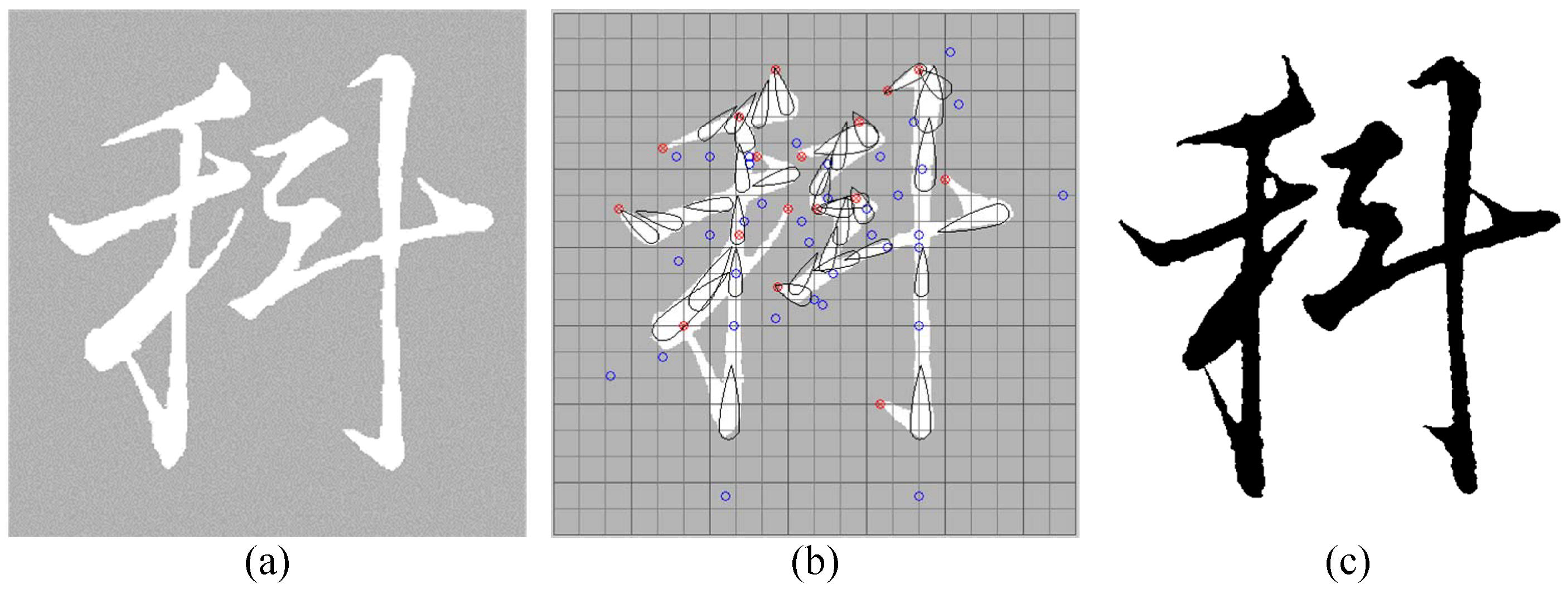
4.2.2. Writing Calligraphy
The result of writing “Ke” with our system is shown in Figure 19. The character in this figure was written by using a model character to determine the coordinates of the handle. If the footprint image that was obtained by calculating the size and positions of the footprints from the statistical chart and handle coordinates is excessively different from the model character, the handle coordinates will then be readjusted. In Figure 19b, the red circles are the handle coordinates where the tip first touches the paper, while the blue circles are the handle coordinates where the handle was pressed downwards. The droplets are the brush footprints, and their sizes and positions were calculated using the brush trajectory model.
Figure 19.
Planning of the calligraphy writing process and the result. (a) Model character from the internet. (b) Differences between the planned trajectory and model character. (c) Character written by the robotic arm.
4.3. Evaluation of the Written Characters
The written characters were evaluated using the methods proposed in [14]. Figure 20 shows the outer frame and intersection points of any two strokes of the character "Yong" where represent the intersection points of any two strokes of the sample and test characters and represent the points on the outer frame of the sample and test characters. and are the shortest and longest distances from to any corner, respectively and and are the shortest and longest distances from to any corner, respectively. To increase the sensitivity of this method to changes in the characters, was changed to . The mathematical equations for the evaluation of character quality are shown below (Equations (9)–(13)).
where and represent the area of the outer frame in test and sample data, respectively. The sample character is used as a reference for quality evaluation.
where and are the X and Y coordinates of the points on the outer frame of the sample and test characters, respectively and and are the X and Y coordinates of the intersection points of any two strokes of the sample and test characters, respectively.
Figure 20.
Outer frame and intersection points of any two strokes of "Yong" character where represent the intersection points of any two strokes of the sample and test characters and represent the points on the outer frame of the sample and test characters.
The s, p, and r parameters were changed to S, P, and R as follows:
Each parameter has a maximum score of 100. The higher the score, the better the quality of the character in that particular aspect.
In Figure 21a, the greyed area is the model character, and the center of each footprint is assumed to be the projected position of the handle. The footprints have been modeled as circles, and the planned trajectory for the footprints in this instance is the arrangement of circles inside the model character. In Figure 21b, the brush trajectory model was used to simulate the footprints and obtain the relative positions of the handle and center of each footprint. In this case, the planned trajectory for the footprints is the arrangement of droplet-like shapes inside the model character. In this study, it was assumed that each calligraphic character consists of trajectories traversed by droplet-shaped footprints. Therefore, these trajectories can be decomposed into a series of droplet-shaped footprints. For purposes of clarity, only a few representative droplet-shaped footprints are shown in Figure 21b.
Figure 21.
Trajectories that model the movement of brush footprints. (a) Footprints modeled by circles. (b) Footprints modeled by the brush trajectory model (Brush Pen #1).
Figure 22 shows the aesthetics evaluation scores of the “Yong” character that was written by the robotic arm using Brush Pen #1 when the handle coordinates were obtained by modeling the brush footprints as circles. Equations (9)–(13) were used to compare this character to the model character in terms of size, position and stroke balance. The differences between the written character and model character were thus quantified in terms of these parameters. Figure 23 shows the aesthetic evaluation scores of the “Yong” character that was written by the robotic arm using Brush Pen #1 when the footprints were modeled using the brush trajectory model to obtain the handle coordinates. Figure 24 shows the aesthetic evaluation scores of the “Yong” using Brush Pen #2 when the handle coordinates were obtained by modeling the footprints using the brush trajectory model.
Figure 22.
Aesthetics evaluation scores of the character that was modeled using circles and written using Brush Pen #1 by the robotic arm. (a) Size: 85.02. (b) Position: 88.60. (c) Stroke balance: 91.98.
Figure 23.
Aesthetics evaluation scores of the character that was modeled using the brush trajectory model and written using Brush Pen #1 by the robotic arm. (a) Size: 93.24. (b) Position: 92.23 (c) Stroke balance: 98.48.
Figure 24.
Aesthetics evaluation scores of the character that was modeled using the brush trajectory model and written using Brush Pen #2 by the robotic arm. (a) Size: 97.98. (b) Position: 89.28 (c) Stroke balance: 97.25.
Figure 22 and Figure 23 were written using Brush Pen #1, and it is intuitively apparent that Figure 23 is superior to Figure 22. This is supported by their scores, which show that Figure 23 is indeed better than Figure 22. Therefore, we have demonstrated that the use of a brush trajectory model improves the quality of robotic calligraphy. Figure 23 and Figure 24 were written using different brush pens, and it is shown in Figure 12 that the brush of Brush Pen #2 has a larger cross-sectional area than that of Brush Pen #1. One may observe that the last stroke of the “Yong” character, a Na stroke, is completely different in Figure 23 and Figure 24. Therefore, the characters written by a brush pen are also affected by the shape of the brush.
5. Discussion and Conclusions
5.1. Discussion
Our experiments have demonstrated that the brush trajectory model can be used to visually guide users in the determination of handle coordinates, which then allow the robotic arm to write calligraphic characters, like the “Sin” character shown in Figure 25. As the writing process is clearly illustrated by the handle coordinates, this approach can be used as an aid in the teaching of calligraphy.
Figure 25.
Effects of different calligraphic techniques on the character. (a) A zuogou stroke that was made without lifting the brush pen. (b) A zuogou stroke made by lifting the brush pen for a brief instant.
Figure 14 shows that the shape of the footprints is highly sensitive to handle height, as different handle heights will alter the width of the footprints’ outer frame and footprint lag. These variations in width and lag will significantly affect the shape and quality of the written character. For example, the first stroke of “Sin” (a dian stroke) will change slightly due to errors in the z-value, even if the same parameters are supplied to the robotic arm. Therefore, for a user to freely write calligraphy using the robotic arm, the robotic arm must have a reasonably high level of precision and accuracy, and the operator must also have an understanding of basic calligraphy techniques.
5.2. Conclusions
The primary objective of this study was to obtain the handle coordinates that will allow a robotic arm to write calligraphic characters by using a brush trajectory model in conjunction with model character coordinates. Our system allows the calligraphy writing process to be digitalized and recorded clearly, which makes it a valuable aid in the teaching of calligraphy. The brush trajectory model was created by leveraging the precision of robotic calligraphy to gain insight about the characteristics of different brush pens and calligraphic techniques, which then allow the handle’s coordinates to be correlated to footprint positions. This was performed by using DLT-corrected images of brush footprints drawn by the robotic arm, and by describing the outer frame of these footprints with Bézier curves. With this approach, we are able to freely vary the character written by the robotic arm, as well as the character’s size and position; the robotic arm may then write any Chinese character by using the appropriate brush pen. Since brush trajectories depend on the brush characteristics such as brush thickness, brush material, and brush hardness, the brush trajectory model is nonlinear and highly complicated. Thus, it is suitable for us to use machine-learning methods to investigate the intractable brush trajectory model from different brushes in the future work. According to the findings of this research, the footprint’s size, lag, and angle are the important factors of the brush trajectory model. Thus, artificial neural networks or decision trees are considered as the regression methods to study the mapping from the horizontal brush handle displacement and the brush handle height to the footprint width, lag, and angle. To prevent overfitting of the machine-learning models, we will collect enough data from different brush sizes and stratify them to build several brush trajectory models for different brush sizes.
Author Contributions
Conceptualization, H.-I.L. and T.-T.L.; methodology, H.-I.L. and T.-T.L.; software, T.-T.L.; validation, H.-I.L. and T.-T.L.; formal analysis, H.-I.L. and T.-T.L.; investigation, H.-I.L. and T.-T.L.; resources, H.-I.L. and X.C.; data curation, T.-T.L.; writing–original draft preparation, H.-I.L.; writing–review and editing, H.-I.L. and X.C.; visualization, H.-I.L.; supervision, H.-I.L. and X.C.; project administration, H.-I.L. and X.C.; funding acquisition, H.-I.L. and X.C. All authors have read and agreed to the published version of the manuscript.
Funding
This research was funded by NTUT-BIT joint research program (grant number NTUT-BIT-104-1).
Conflicts of Interest
The authors declare no conflict of interest.
References
- Baxter, B.; Scheib, V.; Lin, M.C.; Manocha, D. DAB: Interactive haptic painting with 3D virtual brushes. In Proceedings of the SIGGRAPH, Los Angeles, CA, USA, 12–17 August 2001; pp. 461–468. [Google Scholar]
- Girshick, R.B. Simulating Chinese brush painting: The parametric hairy brush. In Proceedings of the SIGGRAPH Poster, Los Angeles, CA, USA, 8–12 August 2004; p. 22. [Google Scholar]
- Baxter, W.; Govindaraju, N. Simple data-driven modeling of brushes. In Proceedings of the 2010 ACM SIGGRAPH Symposium on Interactive 3D Graphics and Games, Washington, DC, USA, 19–21 February 2010; pp. 135–142. [Google Scholar]
- Sun, Y.; Qian, H.; Xu, Y. Robot learns Chinese calligraphy from demonstrations. In Proceedings of the 2014 IEEE/RSJ International Conference on Intelligent Robots and Systems, Chicago, IL, USA, 14–18 September 2014; pp. 4408–4413. [Google Scholar]
- Lam, J.H.; Yam, Y. Stroke trajectory generation experiment for a robotic Chinese calligrapher using a geometric brush footprint model. In Proceedings of the 2009 IEEE/RSJ International Conference on Intelligent Robots and Systems, St. Louis, MO, USA, 10–15 October 2009; pp. 2315–2320. [Google Scholar]
- Miura, K.; Matsui, A.; Katsura, S. Synthesis of motion-reproduction systems based on motion-copying system considering control stiffness. IEEE/ASME Trans. Mechatron. 2015, 21, 1015–1023. [Google Scholar] [CrossRef]
- Chu, N.H.; Tai, C.L. An efficient brush model for physically-based 3D painting. In Proceedings of the 10th Pacific Conference on Computer Graphics and Applications, Beijing, China, 9–11 October 2002; pp. 413–421. [Google Scholar]
- Xu, S.; Lau, F.C.; Cheung, W.K.; Pan, Y. Automatic generation of artistic Chinese calligraphy. IEEE Intell. Syst. 2005, 20, 32–39. [Google Scholar]
- Hira, T.; Iida, K. A study of calligraphic skill by virtual brush-writing with haptic device: Hidden Markov modeling of writing strokes. In Proceedings of the ICCAS 2010, Gyeonggi-do, Korea, 27–30 October 2010; pp. 1751–1754. [Google Scholar]
- Okabe, Y.; Saito, S.; Nakajima, M. Paintbrush rendering of lines using HMMs. In Proceedings of the 3rd International Conference on Computer Graphics and Interactive Techniques in Australasia and South East Asia, Dunedin, New Zealand, 29 November–2 December 2005; pp. 91–98. [Google Scholar]
- Mueller, S.; Huebel, N.; Waibel, M.; D’Andrea, R. Robotic calligraphy—Learning how to write single strokes of Chinese and Japanese characters. In Proceedings of the 2013 IEEE/RSJ International Conference on Intelligent Robots and Systems, Tokyo, Japan, 3–8 November 2013; pp. 1734–1739. [Google Scholar]
- Ma, Z.; Su, J. Aesthetics evaluation for robotic Chinese calligraphy. IEEE Trans. Cogn. Dev. Syst. 2016, 9, 80–90. [Google Scholar] [CrossRef]
- Fan, K.; Li, J.; Li, S. Fine grained control of robotic calligraphy. In Proceedings of the 2018 33rd Youth Academic Annual Conference of Chinese Association of Automation (YAC), Nanjing, China, 18–20 May 2018; pp. 1089–1093. [Google Scholar]
- Nonami, J.; Takegawa, Y. Construction of a support system for learning character balance in transcription for beginners. In Proceedings of the 2014 IEEE 3rd Global Conference on Consumer Electronics (GCCE), Tokyo, Japan, 7–10 October 2014; pp. 26–30. [Google Scholar]
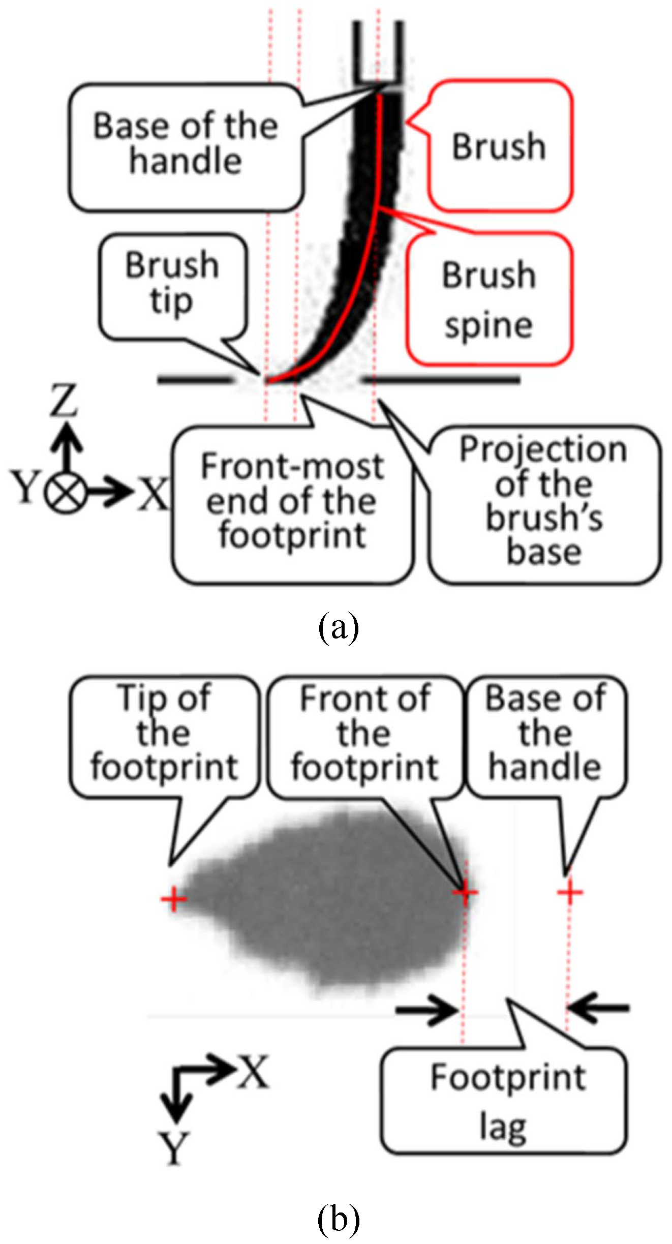
Publisher’s Note: MDPI stays neutral with regard to jurisdictional claims in published maps and institutional affiliations. |
© 2020 by the authors. Licensee MDPI, Basel, Switzerland. This article is an open access article distributed under the terms and conditions of the Creative Commons Attribution (CC BY) license (http://creativecommons.org/licenses/by/4.0/).