1. Introduction
Distributed fiber Raman amplifiers (FRAs) have been regarded as a key technique to achieve high-speed, high-capacity, and long-haul optical transmission systems, owing to their lower noise figures, weaker fiber nonlinear effects, and wider range of amplification characteristics, when compared with Erbium-doped fiber amplifiers (EDFAs) [
1,
2,
3,
4]. Distributed FRAs have also been extensively applied in long-reach unrepeated transmission to provide a cost-effective solution capable of transmitting a high capacity over distances of several hundred kilometers without any in-line active elements [
5,
6]. Raman amplification plays an important role in random feedback fiber lasers [
7] and ultra-long-reach distributed sensing [
8].
Although Raman amplification has promising applications and superior performances, distributed FRA systems have not been prevalent in commercial use, to the best of our knowledge, whereas lumped amplifier systems with EDFAs have widely proliferated [
3]. One of the main challenges for distributed FRAs is the presence of randomly distributed noises, such as spontaneous Raman scattering (SpRS) noise, double Rayleigh backscattering (DRB) noise, and relative intensity noise (RIN) transfer between the pump and the signal lights [
9,
10,
11,
12,
13]. The interactions between the signal and these noises with nonlinear effects are also more complex than those of lumped EDFA systems. The randomness of the noise distributions and the nonlinear interactions make it difficult to model the Raman channel precisely, which limits the applications and the commercial use of distributed FRA systems.
A Raman channel model with an economical computation cost is significant for expanding the applications of distributed FRAs. There are three main types of Raman channel model. The most accurate channel model is used to solve the coupled nonlinear Schrödinger equation (NLSE) of the pump and signal lights [
14,
15,
16]. Unfortunately, there is no general solution for the coupled NLSEs governing different pump architectures. The numerical methods to solve the coupled NLSEs have an extremely high computation cost. When we neglect the pump depletion, the coupled NLSE can be simplified to a simplified NLSE of the signal light. With the equation, we can analyze phenomena such as self-phase modulation (SPM), RIN transfer, and cross-phase modulation (XPM) from the pump lights to the signal lights [
17]. However, pump depletion cannot always be neglected, and it will induce dominant errors in the system with high pump power and high Raman gain. The third type of Raman channel model, which refers to the coupled intensity equations of Raman scattering, is a convenient and widely used tool to analyze the change of signal and pump power along the fiber [
14,
15,
18]. However, the coupled intensity equations cannot describe the change of signal optical fields, which is disabled to analyze the performance of high-order modulation format communication systems with distributed FRAs.
In this paper, referring to the simplified NLSE neglecting pump depletion and the coupled intensity equations of Raman scattering, we propose a novel modified Raman channel model, which describes the propagation of optical signals in fibers governed by a multitude of simultaneous linear and nonlinear phenomena. In our model, we took almost physical processes of distributed FRA into account and employed fewer approximations, which led to a higher accuracy than that of the simplified NLSE neglecting pump depletion and the coupled intensity equations of Raman scattering. When compared with the coupled NLSEs, our model could be solved with an acceptable computation cost. Then, with the experiments, we verified that our model could effectively describe the fiber communication systems employing distributed FRAs. This indicated that our method was more capable of modeling the distributed noise, especially when the latter interacted severely with the signal due to the nonlinear effects.
The remainder of the paper is organized as follows:
Section 2 gives a detailed description of the principle underlying the introduction of our method,
Section 3 describes the experimental setup and the analysis of the results, and
Section 4 draws the conclusions.
2. Principle
The propagation of optical pulses in single-mode communication fibers is typically modeled with the generalized nonlinear Schrödinger equation by [
14]:
In Equation (1), denotes the slowly varying field envelope of the optical signal, and is the propagation distance. Equation (1) is valid in the frame of reference of the pulse traveling with signal group velocity . Using the relation between the retarded time and the present time , Equation (1) can be transformed into the laboratory frame of reference. The parameter models the linear signal loss, and are the coefficients of second- and third-order dispersion, and is the fiber’s nonlinear parameter. Parameters and govern the effects of self-steepening and the Raman response.
For pulses of width
, the last two terms in Equation (1) can be neglected, because the effects of self-steepening and the Raman response are not obvious [
14]. As the contribution of the third-order dispersion term is also quite small for such pulses (as long as the carrier wavelength is not too close to the zero dispersion wavelength), we can employ the simplified equation [
14]:
In the optical fiber communication system with distributed FRAs, taking into account the Raman amplification effects, the simplified NLSE can be written as:
where
is the Raman gain factor with the unit (1/km). However, the accuracy of the model based on Equation (3) is not high enough to allow for the simulation of the performance of the FRA system. To model the systems with FRAs more precisely, we should take into account not only the Raman amplification but also the distributed noise and the XPM between the signal and the pump lights when employing the NLSE.
One of the limiting factors of the FRA system is the distributed noise, mainly induced by the SpRS and DRB.
Figure 1 presents the schematic diagram of a bidirectional pumped distributed FRA system and the DRB noise generation process in the system. Two pump waves coupled at the beginning and the end of the fiber link led to distributed Raman gain in the fiber. The signal light was transmitted along the forward direction of the fiber and scattered randomly. A little part of the backscattered guided photons would generate the single Rayleigh backscattering (SRB) light. The SRB light was amplified by the Raman pump lights and backscattered randomly again to produce DRB light. The amplified DRB light was partially coherent with the signal light and could interfere with the signal light. The DRB noise was the summary of a mass of lights with different time delays when compared with the signal light, which can be regarded as the stochastic multi-path interference (MPI) noise [
11]. The MPI noise can be negligible in the long-haul multi-span fiber system but can impact the performance of the long-reach unrepeated system and the distributed random feedback lasers. In addition, when the two pump waves were transmitted along the fiber, the SpRS photons were generated, and the forward-guided photons were also amplified [
9,
10]. Besides, the intensities of the Raman pump lights varied with time, and the variety of pump intensities could change the Raman gain and the intensity of the signal light, referred to as the RIN transfer [
13]. The RIN transfer and the XPM were dependent on the group delay between the signal and the pump lights [
17].
Generally, the Raman pump sources are broadband continuous wave lasers. We can thus modify the loss parameter to model the amplification. Then, the SpRS and DRB noises can be regarded as bandlimited additive noises. The RIN transfer can be modeled by the variety of the Raman gain [
13,
17]. Therefore, Equation (2) can be modified as:
In Equation (4), the first term at the right side refers to the effects of fiber attenuation and Raman gain. We recorded the Raman gain changes with time in order to model the RIN transfer. The second term describes the impact of the second-order dispersion, while the third and fourth terms refer to the SPM of the signal light and the XPM between the signal and the pump lights. We modeled the RIN of the pump laser as 1/(f^ν) of the frequency noise [
19]. Since the FRAs are independent from polarization, we should induce the factor 2/3 to describe the influence of the polarization effects on the XPM [
14,
17]. The last term,
, is used to model the bandlimited additive distributed noise in the FRA systems, such as the SpRS and DRB noises.
To obtain the influence of the RIN transfer, we should solve the dynamic coupled intensity equations of the bidirectional Raman amplification regarding location and time, but the required computational cost is too high. As an alternative solution, we can solve the static coupled intensity equations in different time periods to acquire a series of
. To reflect the influence of the group delay between the signal and the pump lights, the time variable
is induced. In the forward-pumped FRA system,
and in the backward-pumped FRA system,
The static value of the parameter
can be calculated using the coupled intensity equations of Raman scattering [
15,
18]:
In Equation (7), + and − denote the forward and backward propagation of lights in the fiber, respectively; and represent the pump power at frequency and the power of the amplified signal light at frequency ; and are the attenuation coefficients for the pump light and the signal light; is the Raman gain factor from the pump light to the signal light; the term represents the spontaneous Raman emission in the signal band; is the bandwidth of the signal light or the generated spontaneous radiation; and and are the Rayleigh scattering coefficients for the pump light and the signal light. The fibers in our experiments were standard single-mode fibers (SSMF, SMF-28e).
Then, the parameter
can be expressed as:
In Equation (4), the influence on signal transmissions of the RIN transfer is described by . In the numerical method, the difference between and can be modeled by the variable elements shift.
In Equation (4), the distributed noise
mainly includes the SpRS noise and DRB noise in the distributed FRA systems. The power of the SpRS noise within a segment can be expressed as:
Based on the power of the SpRS noise, we generated a complex Gaussian noise sequence as the optical field of the SpRS .
According to the generating progress of the DRB noise, we took the Raman gain and the two-times Rayleigh backward scatterings into account to get the optical field of the DRB noise. Assuming that the once and twice back reflection locations are
and
, respectively, the slowly varying field envelope of the DRB noise can be expressed as follows:
In Equation (10),
is the Rayleigh backscattering (RB) coefficient with the unit (1/km), which can be modeled as a complex white Gaussian zero-mean process.
is the transform function of the electrical field amplitude when the DRB field propagates along the fiber from
to
. Neglecting the influence of the nonlinear effects and the dispersion on the DRB field propagation,
can be expressed as:
and are the signal powers at and , which can be calculated using Equation (7).
Therefore, the field of additive distributed noise generated in one fiber can be written as:
Except for the SpRS and DRB noises, the ASE noise of the EDFA at the transmitter was regarded as the centralized additive complex Gauss noise. The complex Gauss noise was added to the link at the positions of the EDFAs.
3. Experiments
To verify our model, we simulated different types of fiber systems with FRA, employing our modified NLSE in Equation (4) and the simplified NLSE in Equation (3). In the simulations, we employed the split-step Fourier method (SSFM) to simulate the performance of the fiber system, and the number of steps was always 1000. The computation cost of the SSFM was obtained from the FFT/IFFT operation. With the same number of steps, both our model and the simplified NLSE required 1000 pairs of FFT/IFFT operations. The computation cost of our model and the simplified NLSE in the SSFM were almost the same. The increased computation was due to the noise calculation by Equations (7) to (12). Therefore, the computation cost was acceptable.
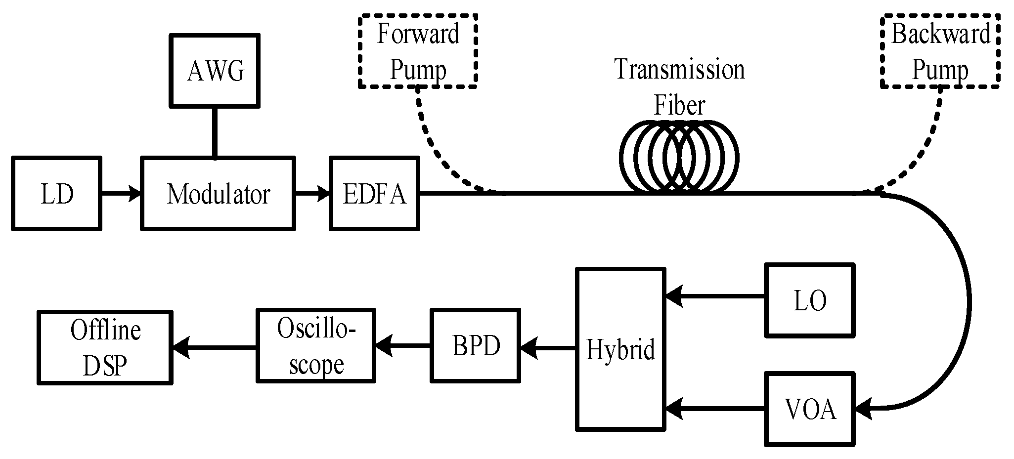
Then, we compared the simulating results with the experiments. The system architecture of our experiments and simulations is shown in
Figure 2.
At the transmitter, a 1550 nm wavelength laser with 100 kHz linewidth and an IQ modulator were used for optical modulation. A pseudo-random binary sequence (PRBS) of length 2
24 was generated by the software. After serial-to-parallel conversion and constellation mapping, the data of the I/Q channels were written to an arbitrary waveform generator (AWG). The raw data were mapped using 16 QAM in our experiments and simulations. The baud rate of the symbol was 10 GBaud/s, and the working AWG was at a 10 GS/s sampling rate with 8-bit resolution. The output signal of the AWG in the two channels was sent to the IQ modulator through radio-frequency amplifiers. The modulated optical signal was fed into an EDFA to adjust the optical launch power. Then, the optical signal was transported through the fiber link and reached the receiver. At the receiving end, we employed a variable optical attenuator (VOA) to control the input optical power of the balanced photonics detector (BPD). The two output electrical signals of the BPD were acquired by a digital sampling oscilloscope with a 40 GS/s sampling rate. Subsequently, the offline digital signal processing (DSP) was employed to recover the data carried by the light. The offline DSP included electrical dispersion compensation (EDC), IQ orthogonalization, carrier recovery, and error–vector magnitude (EVM) calculation. The EVM was defined as follows:
where
is the normalized symbol in the stream of received symbols,
is the corresponding ideal normalized constellation point,
is the number of symbols in the received stream, and
is the absolute value of the longest ideal normalized constellation vector.
We measured the signal under different circumstances, including the 180 km link with only backward-pumped FRA and the 250 km link with both forward- and backward-pumped FRA. The efficient gains of the forward- and backward-pumped FRA were 10 dB and 16 dB, respectively. We also measured the 6-span 480 km fiber link, in which each span included an 80 km fiber, a backward-pumped FRA with 16 dB gain, and a VOA to adjust the optical launch power. The received optical power at the BPD was fixed at −25 dBm by adjusting the VOA. In the three circumstances, we changed the optical launch power to obtain the variation of EVM.
Figure 3a illustrates the simulating results and the experimental results of the 180 km fiber link with only backward-pumped FRA. The black diamonds are the experimental results, and the red and blue curves are the simulating results of the simplified NLSE and our model, respectively. In the single-span system with only backward-pumped FRA, both the simplified NLSE and our model could simulate the system precisely. The root mean squared error (RMSE) between the EVM of the simplified NLSE and the experimental results was 0.490%; the RMSE between the EVM of our model and the experimental results was 0.431%.
Figure 3b showed the simulating results and the experimental results of the 250 km fiber link with both forward- and backward-pumped FRA. In
Figure 3b, the simulating results of our model were obviously different from those of the simplified NLSE. The RMSE between the EVM of the simplified NLSE and the experimental results was 0.889%; the RMSE between the EVM of our model and the experimental results was 0.492%. In particular, when the launch power was about 4 dBm, the EVM curve simulated through the simplified NLSE began to increase. However, in the simulating results of our model, the EVM curve increased when the launch power was higher than 5 dBm and increased more slowly than that of the simplified NLSE. Compared with the experimental results, our model could obtain the optimal launch power more adequately.
The simulating results and the experimental results of the 6-span 480 km fiber link are shown in
Figure 3c. The fiber link included six spans, each with an 80 km fiber, a 16 dB-gain back-pumped FRA, and a VOA. In the experiments, we adjusted the VOA to keep the launch power of each span the same. In the multi-span fiber link, the optimal launch power was much lower than that of the single-span system, because of the more apparent nonlinear effects. In
Figure 3c, when the signal launch power was higher than −5 dBm, it was obvious that the simulation results based on our model fit better with the experiments than those of the simplified NLSE. When the signal launch power was lower than −5 dBm, the performances of our model and the simplified NLSE were not sufficiently different. Another remarkable difference between our results and those of the simplified NLSE was the different optimal launch power. In simulations based on our model, the optimal launch power was about −7 dBm, but the optical launch power obtained by the simplified NLSE was about −4.5 dBm. In the experiments, the optimal launch power was in the range of −5 dBm to −6 dBm. The simplified NLSE model had a higher accuracy on the simulation of the optimal launch power. The RMSE between the EVM of the simplified NLSE and the experimental results was 7.396%; the RMSE between the EVM of our model and the experimental results was 1.299%.
4. Discussion
In the experiments, we compared the simulation results of our model and the simplified NLSE with the experimental results of the fiber systems with only backward-pumped FRA (system A), both forward- and backward-pumped FRA (system B), and a 6-span 80 km fiber with a 16 dB-gain back-pumped FRA (system C).
In system A, there was only a small difference between the two models. When the optical launch power was higher than 9 dBm, the EVM in our model increased a little more sharply than that of the simplified NLSE. This might have been caused by the influence of the RIN transfer between the pump light and the signal light. In the simplified NLSE, all noise was regarded as the centralized additive white Gaussian noise (AWGN) and added to the signal field at the receiver. However, the RIN had a distributive impact on the signal in our model, which was more sensitive to the fiber transmission. Since there was little difference, in the experiments, between the errors of our model and those of the simplified NLSE, we could not tell which model was better.
For system B, in the system with forward-pumped FRA, the RIN and SpRS noises were more severe. Since the signal power was high, the distributed noise could interact with the signal for the nonlinear effects. Therefore, the distributed noise could not be regarded as centralized AWGN at the high launch power.
In system C, the simulating results of our model fit better with the experimental measurements, which confirmed that our model could effectively describe the multi-span system with backward-pumped FRA.
In summary, our modified model had a better performance with regard to the simulation of the fiber system with forward FRA and high nonlinear effects, whereas the simplified NLSE model was suited to the conventional fiber systems with EDFA and the single-span fiber system with only backward FRA.
5. Conclusions
In this paper, we proposed a modified Raman channel model, which described the propagation of optical signals in fibers governed by a multitude of simultaneous linear and nonlinear phenomena. In our model, we took almost physical processes of distributed Raman amplification into account, such as the distributed Raman gain, the RIN transfer from pump lights to the signal light, the distributed SpRS and DRB noises, the centralized ASE noise, and the XPM between the signal and the pump lights. Given that fewer approximations were employed, our model achieved a higher accuracy than that of the simplified NLSE.
Then, with the experiments, we verified that our model could effectively describe the fiber communication systems employing distributed FRAs. With the comparisons of the EVM curves, our model displayed lower errors in the experimental results regarding the bidirectional pumped FRA single-span fiber systems and multi-span systems with backward-pumped FRAs. This indicated that our method was more capable of modeling the distributed noise, especially when the latter interacted severely with the signal due to the nonlinear effects.


