Abstract
A new replaceable hysteretic damper to better control seismic building damage, consisting of two or more adjacent steel vertical elements connected to each other with continuous mild/low strength steel shear links, is proposed and investigated in this paper. New Dampers, called Dissipative Columns (DC), continuously linked with X-shaped steel plates, provide additional stiffness and damping to a lateral system by using a basic and minimally invasive construction element: the column. Working in a way similar to coupled shear walls, the proposed element behavior is theoretically analyzed at linear and non-linear ranges. In fact, considering different restrained cases, a parametric analysis is developed in order both to evaluate the effect of the main geometrical and structural parameters and to provide the design capacity curves of this new damper. The DC can be considered a new damping device, easy to install in new as well as existing buildings in order to protect them from seismic damage.
1. Introduction
Strong earthquakes have shown that a large percentage of buildings in the affected areas, even if properly built and designed according to the most advanced codes, suffer such severe damages that they need to be demolished after the quake, since they would be expensive to repair. As is known, the acceptance of such level of damage due to severe earthquakes is related to the ductility-based design criteria that assume design seismic actions decrease by reduction factors. This approach may lead to high social and economic costs to the affected communities, and to a long recovery time for essential services and production activities. Inspired by new performance criteria, there is a growing belief that code design criteria are not sustainable for the high level of accepted damage, are impossible to repair, and that common buildings should be designed with a higher performance level. At the beginning of this century, performance based engineering [1] introduced new principles with the scope to select more articulated targets better corresponding to different building roles and use, defining a variety and complex subdivision of performance objectives for seismic events with different intensities and frequencies of occurrence. The “Direct Displacement Based Design” philosophy [2] relates the specified performance level to the strain or drift limits for a specified seismic intensity.
With the scope of minimizing structural damage, several dampers [3,4] as well as new strategies and integrated design approaches [5,6] have been developed in order to dissipate seismic input energy outside of the primary structure and new replaceable hybrid composite steel devices [7,8] have been recently proposed. Dampers can absorb a significant portion of the input energy reducing the hysteretic energy demand to the primary structural elements.
The damage in the main structural members can be prevented or minimized by connecting beams and columns with hinges, and by employing lateral-load resisting members to withstand lateral seismic load. In this case, most of the energy dissipation and structural damages caused by an earthquake will be concentrated on the lateral-load resisting members, and the main members will remain elastic. After the earthquake, the damaged lateral-load resisting members can be replaced easily at reasonable cost. The energy dissipation or damage prevention capacity of a steel framed structure can be greatly enhanced by employing buckling-restrained braces (BRBs). The structure system is composed of a hinge-connected main structure, which is designed to remain elastic under seismic load, and BRBs resisting all lateral loads. The BRBs dissipate most of the vibration energy through inelastic deformation while the other structural members remain elastic and undamaged. During a seismic event, the BRBs dissipate dynamic energy through stable hysteretic behavior [9].
In [10] Low Yielding Strength (LYS) steel is investigated for improving the ductility capacity of box-shaped steel bridge piers and experimental work is carried out for four specimens having different thickness and sectional configurations for cyclic loading test. The test results reveal that the LYS steel portion with longitudinal stiffeners greatly improves the strength and ductility capacity of box columns and it is observed that LYS steel has a great cyclic strain-hardening characteristic. The advantage of use of LYS steel is that it can effectively use large plastic deformation in component plates and the failure of column is concentrated at the LYS steel segment and the energy dissipation occurs far beyond the yield point.
The aim of this paper is to propose and investigate a new replaceable hysteretic damper having a basic form of the art of building, minimally architecturally invasive, consisting of two or more dissipative steel columns directly connected to two consecutive floors linked to each other with X-shaped low/mild steel plates. It will be shown that the new element is able to add significant stiffness and damping to the structural system to reduce seismic response and damage in primary structural members under severe earthquakes. The Dissipative Columns (DC) element will be investigated through non-linear pushover analyses useful to design the yielding properties of the proposed damper depending both on the characteristics of the primary structure and the expected performance as discussed by [11].
2. The Dissipative Column Concept
The proposed Dissipative Column models are shown in Figure 1 for two different configurations (models A and B). The elements can be considered as a sort of framed bi-pendulum with height equal to H, connected in parallel to the primary structure, able to react to the story drift Δ with a lateral force QD adding stiffness, strength and damping. The design concept of the DC element aims to obtain a lever mechanism by which a small inter-story drift provides an amplified vertical drift in the X-plate ends reacting with shear forces as shown in Figure 2. The X-shaped steel plates made of mild or Low Yielding Strength (LYS) steel, having length a, thickness t, width at the ends b and vertical distance i, are also used as shear links between coupled elements.
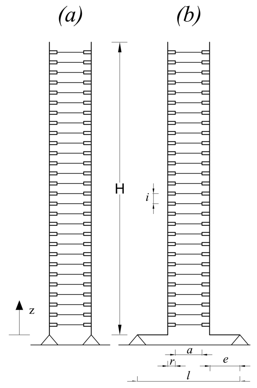
Figure 1.
Dissipative Column Model: (a) Model A: Hinged at the ends; (b) Model B: Eccentrically Hinged at the base.
As for the model B, each lever arm is characterized by an eccentricity e. In both models, r is the rigid element representing half section of each column (Figure 1 and Figure 2).
The top ends of the two models are linked to the upper floor through slotted bolted connections to allow large vertical displacements. As is known, well designed hysteretic dampers in framed structures should dissipate large rates of seismic input energy to control inter-story drift and damage in the primary structure.
By yielding a large volume of steel, the shear devices dissipate substantial input energy during earthquakes or strong winds, while also increasing damping in the entire system with the aim to reduce the damage in the primary system. With reference to reinforced concrete structures, the limit values of Inter-Story Drift Angle (ISDA) corresponding to different structural performance levels are suggested by Ghobarah [12].
The great advantages of DC elements, if compared with classical steel dissipative braces [9], are the reduced architectural invasiveness, so that they are able to be integrated in any building, the ease of installation everywhere, replacement after earthquakes and the stable behavior in cyclic reversal deformation. Axial forces should be designed in order to be transferred locally to a proper structural element.

Figure 2.
Eccentric Dissipative Column Model: Dissipative amplified mechanism.
3. Simplified Non-Linear Analysis of Doubly-Hinged DC
The vertical drift δ between the ends of generic shear link in the elastic range, being the curvature χ constant along each half plate, is related to shear force Vd developed by each X shaped plate, as:
where a, t, b, E are, respectively, the X-plate length, thickness, width at the ends and E is Young’s modulus of steel plates. The axis x represents the barycentric axis of a generic steel plate. Hence, the single X-plate vertical stiffness is equal to:
With reference to the model A, a simplified analysis of the DC behavior subjected to relative displacement can be easily carried out assuming that the column flexural deformation is negligible in respect to the one of flexible inextensible links. An inter-story drift produces a shear drift angle γ and vertical drifts δ along the X-shaped steel plate. Under such simplified assumptions, the top-base relative displacement Δ of a DC element with height H is related to the drift angle γ as:
Therefore, each X-plate undergoes a vertical drift equal to:
where l represents pin axes distance (Figure 2).
Therefore, the uniform distributed vertical load due to the shear drift angle γ applies:
where i represents the plates vertical distance.
The term (l − a)/2 = r represents a small lever arm that can be amplified using eccentricity e between the vertical axis and the supports as will be shown in the following. The axial force at the base of each column is equal to:
For the equilibrium, lateral force-displacement relationship is expressed as:
where KD represents the lateral stiffness of the Dissipative Column given by:
According to experimental tests [13,14], the load-deformation curve of the X-shaped mild steel plates can be idealized as a bilinear curve with a ratio of post yielding stiffness to the initial one equal to 0.03 and available displacement ductility ratio μ = δ/δy in the range between 3 and 5 [15]. Since yielding strength fy is reached almost uniformly along the device, the yielding vertical load py can also be expressed as:
while the relative yielding displacement of each link can be written as:
Therefore, the lateral yield strength of the doubly hinged DC element can be evaluated as:
and the yielding displacement applies:
The bending moment along each column under a lateral force QD results:
where z represents the vertical axis having origin in the hinge (Figure 1).
The dimensionless theoretical force-displacement relationship of a DC element consisting of two HE220 steel columns with H = 3.5 m linked to each other through X-shaped mild steel plates having a = 200 mm, b = 200 mm, t = 10 mm, i = 50 mm, l = 480 mm, is plotted in Figure 3.
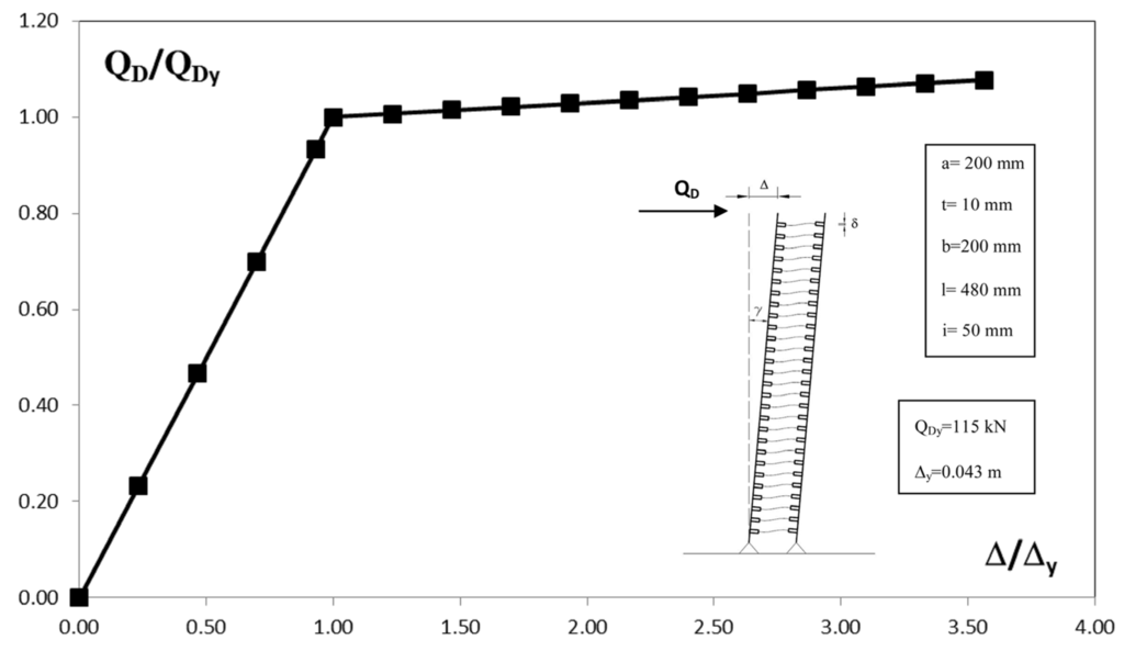
Figure 3.
Model A: Theoretical force-displacement relationship.
Considering X-shaped LYS steel plates having yield strength 97.9 MPa at 0.2% offset strain with Young’s modulus equal to 200 GPa, a parametric analysis of the DC element is developed in order to evaluate the effect of the flexible devices for different values of i and t. The results of the parametric analysis, illustrated in Figure 4, show that lateral stiffness and strength increase with greater values of t and with lower values of i.

Figure 4.
Model A: parametric analysis for different values of i and t.
Differently to the previous case, in presence of a significant eccentricity the column flexural deformation should not be neglected, therefore, the top-base relative displacement Δ of the DC element results being:
and each X-plate undergoes a vertical drift δ (z):
where E, Ic, Ie and (l − a) = 2(e + r) are, respectively, Young’s modulus, inertia of each column, lever arm and the lever arm with the eccentricity e.
The uniform distributed vertical load applies:
The axial force at the base of each column is equal to:
For the equilibrium, lateral force can be expressed as:
4. Results of Non Linear Pushover Analyses
The responses of the DC elements have been analyzed by static pushover analyses using SAP2000 software [16]. The displacement-controlled pushover analyses have been performed until to reach 150 mm in terms of relative displacement modeling the non-linear response of the steel plates through the Ramberg-Osgood (RO) curve with a ratio of post yielding stiffness over the initial one equal to 0.03. The analyzed dampers are composed of two steel columns with different X-plates varying width, thickness and yield stress. Mechanical and geometrical properties of the tested models (models A and B) are shown in Table 1.

Table 1.
Geometrical and structural properties of the Dissipative Column (DC) elements.
| Model | Plate Thickness t (mm) | Height H (mm) | Plate Length a (mm) | Plate Distance i (mm) | Plate Width b (mm) | Plate Yield Stress fy (N/mm2) | Column Distance l (mm) | Eccentricity e (mm) | Column Profile |
|---|---|---|---|---|---|---|---|---|---|
| A_1 | 5 | 3500 | 200 | 50 | 200 | 240 | 480 | 0 | HE220B S235 |
| A_2 | 10 | ||||||||
| A_3 | 15 | ||||||||
| A_4 | 20 | ||||||||
| B_1 B_2 B_3 | 5 10 15 | 3500 | 200 | 50 | 150 | 100 | 360 | 0 | HE160B S460 |
| 560 | 100 | ||||||||
| 760 | 200 | ||||||||
| 960 | 300 |
With reference to model A, the displacement-controlled pushover curves of the DC models until to reach 150 mm for different thickness values are illustrated in Figure 5.
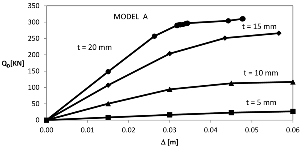
Figure 5.
Model A: Pushover curves for different plate thickness.
The diagrams of the column bending moment, axial force, link bending moment related to model A_2 (t = 10 mm) are represented in Figure 6. The column bending moment is characterized by discontinuities in correspondence of each shear link due to the bending moments developed on each plate, as shown in Figure 6a. The axial force distribution along the columns is linear, in a manner consistent with the simplified assumptions previously examined, as shown in Figure 6b. Both columns remain quite far from their elastic limits (Figure 7) [17], while shear links immediately enter the plastic range as the lateral force increases. In particular, the steel plates located lower are able to dissipate more energy than the ones located higher, as shown in Figure 6c.
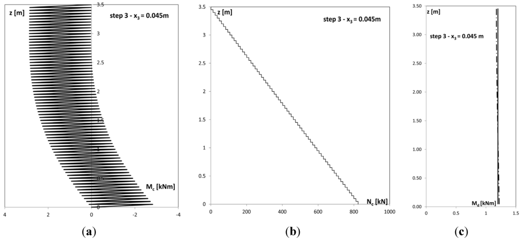
Figure 6.
Model A_2: (a) Column Bending Moment; (b) Axial Force; (c) Link Bending Moment.
The model A_4 collapses before due to excess of non-linear deformations as demonstrated in Figure 7.

Figure 7.
Model A_2: Stress Points on MN Domain at last pushover step.
Comparisons between theoretical and numerical DC behavior of model A are plotted in Figure 8 and Figure 9. Force-displacement relationships result comparable and consistent with the assumption that the column deformation can be considered as a rigid neglecting the small curvature respect to the shear links’ one. The maximum ductility factor μ = δ/δy demanded to model A X-plates, at the last considered step (150 mm), lower than the values suggested by [15], is shown in Figure 10.

Figure 8.
Model A_2: Theoretical vs. pushover analysis force displacement relationship.
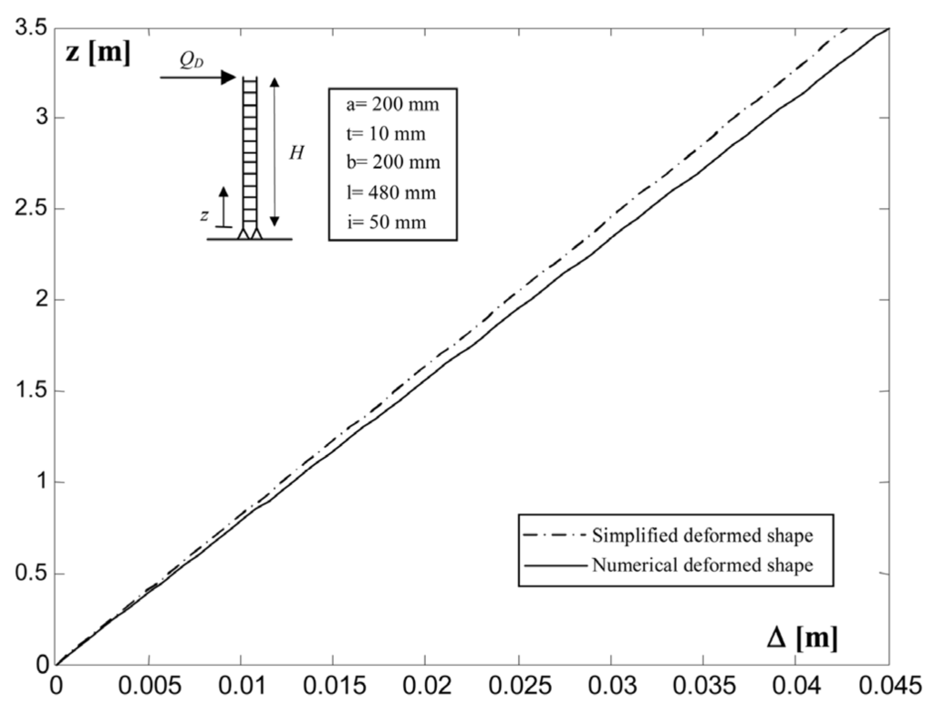
Figure 9.
Model A_2: Simplified vs. numerical deformed shapes.

Figure 10.
Model A: Displacement ductility requirements for steel plates at the last step.
With reference to model B, with eccentricity, the pushover curves for different X-plate thickness and eccentricity values, are shown in Figure 11a–c.

Figure 11.
Model B: Pushover curves for different eccentricity e and plate thickness t: (a) t = 5 mm; (b) t = 10 mm; (c) t = 15mm.
Results show that the higher value of eccentricity produces an increase in both stiffness and lateral strength, while X steel plates yield lower displacement Δ. It follows that the DC element with significant eccentricity is able to add more stiffness and lateral strength to the primary structure and dissipate more energy than the small eccentricity case under the same displacement Δ. Figure 12 shows the displacement ductility factor along the height of the model B_2, required at displacement Δ equal to 0.045 m for different values of eccentricity. Figure 12 also shows that the steel plates located higher are able to dissipate more energy than the previous configuration presenting higher values of the demanded ductility factor and confirming the effectiveness of the eccentric DC element.

Figure 12.
Model B_2: Displacement ductility requirements for steel plates at 4th step.
5. Multi-Bay Dissipative Columns
With reference to double-hinged model, in several cases it is possible to adopt multi-bay dissipative columns organized as represented in Figure 13. Let us consider the case of an assembled n DC elements, assuming the same simplified hypothesis used for the two adjacent columns case. The assembled system story drift is related to the shear drift angle γ as:

Figure 13.
Multi-bay dissipative columns.
The i-th bay transmits to the column a uniformly distributed load pi given by:
Therefore, the internal columns are not subjected to axial force while only the two external ones reach, at the base, the axial force expressed by:
The n-bays assembled dissipative columns react through a shear force given by:
where KD is the sum the lateral stiffness developed by the links of each bay. Similarly, the post yield stiffness of the multi-bay element is equal to the sum of the single-bay one.
The responses of some multi-bay DC elements have been investigated through static pushover analyses. Adopting X-shape plates made of LYS steel, the yielding displacement and lateral strength obviously decrease as well as the axial force in both columns.
Multi-bay dissipative columns equipped with X-shape plates made of LYS steel represent a design solution to obtain higher lateral stiffness and low strength. Figure 14 comparatively shows the response curves for the case of 6-bays and 1-bay DC elements equipped with LYS steel X-shape plates between S235 HE220 steel columns having properties reported in Table 2.
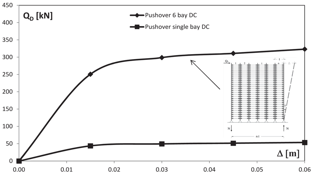
Figure 14.
Six bays vs. single bay DC pushover curves.
Table 2.
Geometrical and structural properties of the n-bay DC elements with Low Yielding Strength (LYS) steel plate.
| Model | Height H (mm) | Column Distance l (mm) | Plate Length a (mm) | Plate Thickness t (mm) | Plate Distance i (mm) | Plate Width b (mm) | Plate Yield Stress fy (N/mm2) | Restrains |
|---|---|---|---|---|---|---|---|---|
| 1-bay DC | 3500 | 480 | 200 | 10 | 50 | 20 | 100 | model A |
| 6-bays DC | 3500 | 480 | 200 | 10 | 50 | 20 | 100 | model A |
Then a parametric analysis has been carried out in order to define the force-displacement relationship of the model for different values of the thickness t, number of bays and plates distance i (Figure 15).

Figure 15.
Parametric analysis of the force-displacement relationships of the model for different values of the thickness t, number of bays and plates distance i.
As shown in Figure 15, adopting X-shape plate made of LYS steel, the lateral stiffness and strength of the Multi-bay dissipative columns increase for lower values of i and for more bays. The yielding displacement decreases as device thickness increases.
6. Conclusions
A new replaceable hysteretic steel damper to control seismic building damage consisting of two or more adjacent steel Dissipative Columns (DC) connected to each other with continuous mild/low strength steel X-shaped plates, has been proposed and investigated.
The behavior of the proposed DC element with two different configurations has been investigated at linear and non-linear ranges, developing several parametric analyses in order to evaluate the hysteretic performances.
Numerical tests showed that doubly-hinged DC elements with low eccentricity can fully yield along their length while columns are subjected to axial strain and so, small bending moments can be neglected flexural deformation.
In the presence of significant eccentricity, large bending moments have been observed that affect the section size. Eccentricity acts as a mechanical lever arm in order to amplify energy dissipation increasing plate vertical drift producing easier yielding conditions in hysteretic dampers.
In any case, lateral stiffness increases for greater values of the X-shaped plate thickness and for lower values of their distance, and for greater eccentricities between bearings and column axes. For greater values of the device thickness, the yielding displacement decreases as well as for lower values of link steel strength. Strongly coupling dissipative affects can be obtained by using a mechanical lever to amplify the X-plate drift. The greater is the eccentricity, the higher the bending moment.
Multi-bay dissipative columns with X-shape plate made of LYS steel represent a design solution to obtain higher lateral stiffness and lower strength, while also strongly reducing the axial force in the internal columns. The number of DC elements should be designed for the buildings where they are to be installed.
The DC elements can be considered as new low-yield, ductile replaceable and minimally invasive dampers easy to install to new as well as to existing buildings, providing significant additional stiffness, strength and damping to a structural system potentially capable to reduce building seismic response and damage in primary structural members under severe earthquakes.
Author Contributions
Bruno Palazzo, Paolo Castaldo and Ivana Marino conceived the idea and designed the numerical analyses; Paolo Castaldo and Ivana Marino performed the numerical analyses; Bruno Palazzo, Paolo Castaldo and Ivana Marino analyzed the data; Bruno Palazzo, Paolo Castaldo and Ivana Marino wrote the paper.
Conflicts of Interest
The authors declare no conflict of interest.
References
- California Office of Emergency Services (OES). Vision 2000: Performance Based Seismic Engineering of Buildings; Structural Engineers Association of California: Sacramento, CA, USA, 1995.
- Priestley, M.J.N. Myths and fallacies in earthquake engineering-conflicts between design and reality. Bull. NZNSEE 1993, 26, 329–341. [Google Scholar]
- Symans, M.D.; Charney, F.A.; Whittaker, A.S.; Constantinou, M.C.; Kicher, C.A.; Johnson, M.W.; McNamara, R.J. Energy dissipation system for seismic applications: Current practise and recent developments. J. Struct. Eng. 2008, 134, 3–21. [Google Scholar] [CrossRef]
- Wada, A.; Watanabe, A.; Connor, J.; Kawai, H.; Iwata, M. Damage Tolerant Structures. In Proceeding of the Fifth U.S.-Japan Workshop on the Improvement of Building Structural Design and Construction Procedures, ATC-15, San Diego, CA, USA, 8–10 September 1992.
- Castaldo, P. Integrated Seismic Design of Structure and Control Systems; Springer International Publishing: New York, NY, USA, 2014. [Google Scholar]
- Castaldo, P.; de Iuliis, M. Optimal integrated seismic design of structural and viscoelastic bracing-damper systems. Earthq. Engng Struct. Dyn. 2014, 43, 1809–1827. [Google Scholar]
- Pampanin, S. Emerging solutions for high seismic performance of precast-prestressed concrete buildings. J. Adv. Concr. Technol. 2005, 3, 202–222. [Google Scholar] [CrossRef]
- Pampanin, S. Reality-Check and Renewed Challenges in Earthquake Engineering: Implementing Low-Damage Structural Systems-From Theory to Practice. In Proceeding of the 15WCEE, Lisbon, Portugal, 24–28 September 2013.
- Kim, J.; Seo, Y. Seismic design of low-rise steel frames with buckling-restrained Braces. Eng. Struct. 2004, 26, 543–551. [Google Scholar] [CrossRef]
- Susantha, K.A.S.; Aoki, T.; Kumano, T.; Yamamoto, K. Application of Low-Yield Strength Steel in Steel Bridge Piers. In Proceeding of the 13th WCEE, Vancouver, Canada, 1–6 August 2004.
- Oviedo, A.J.A.; Midorikawa, M.; Asari, T. Earthquake response of ten-story story-drift-controlled reinforced concrete frames with hysteretic dampers. Eng. Struct. 2010, 32, 1735–1746. [Google Scholar] [CrossRef]
- Ghobarah, A. On Drift Limits Associated with Different Damage Levels. In Proceedings of the International Workshop on Performance-Based Seismic Design, Department of Civil Engineering, McMaster University, Bled, Slovenia, 28 June–1 July 2004.
- Aiken, I.; Nims, D.; Whittaker, A.; Kelly, J. Testing of passive energy dissipation systems. Earthq. Spectra 1993, 9, 335–370. [Google Scholar] [CrossRef]
- Whittaker, A.; Bertero, V.; Alonso, J.; Thompson, C. Earthquake Simulator Testing of Steel Plate Added Damping and Stiffness Elements; Report No. UCB/EERC-89/02; Earthquake Engineering Research Center, University of California: Berkeley, CA, USA, 1989. [Google Scholar]
- Whittaker, A.S.; Bertero, V.V.; Thompson, C.L.; Alonso, L.J. Seismic testing of steel plate energy dissipation devices. Earthq. Spectra 1991, 7, 563–604. [Google Scholar] [CrossRef]
- SAP2000 vers; Computers Structures Inc.: Berkeley, CA, USA, 2010.
- European Committee for Standardization (CEN). Eurocode 8 Part 1: General Rules, Seismic Actions and Rules for Buildings; CEN: Brussels, Belgium, 2005. [Google Scholar]
© 2015 by the authors; licensee MDPI, Basel, Switzerland. This article is an open access article distributed under the terms and conditions of the Creative Commons Attribution license (http://creativecommons.org/licenses/by/4.0/).