Article

Hysteretic Behavior of Traditional Chinese Wooden Joints Reinforced with Nitrile Butadiene Rubber-Based Viscoelastic Dampers: Experimental Study and Simplified Simulation Method


1
College of Civil Engineering, Nanjing Forestry University, Nanjing 210037, China
2
Faculty of Architecture and Civil Engineering, Huaian University, Huaian 223003, China
*
Author to whom correspondence should be addressed.
Buildings 2026, 16(11), 2183; https://doi.org/10.3390/buildings16112183
Submission received: 9 May 2026 / Revised: 26 May 2026 / Accepted: 28 May 2026 / Published: 29 May 2026
(This article belongs to the Special Issue Performance and Analysis Methods of Timber Structures)

Abstract

The nitrile butadiene rubber-based viscoelastic damper (NVED) has been proven effective in improving the seismic performance of various types of structures. This study proposes to enhance the hysteretic behavior of traditional Chinese wooden joints using the NVED. The cyclic tests on the NVED are first conducted to derive their mechanical properties. Secondly, two configurations of the mortise-tenon joints are selected as the prototype models to fabricate four specimens, and the hysteretic loading tests are conducted on the specimens to derive their hysteretic behaviors. Comparisons are made between the models with and without the NVED to clarify its reinforcing effects. On the basis of the test results of the mortise-tenon joints and the NVED, a simplified simulation method is proposed to represent the joints with the NVED. The test results show that the installation of the NVED can remarkably improve the hysteretic performance of mortise-tenon joints throughout the entire loading process. Compared with the unreinforced joints, the bearing capacity and energy dissipation of the NVED-reinforced specimens can increase by approximately 40%, particularly under large deformation conditions. The proposed simplified simulation method, which adopts zero-length elements to simulate the rotational response of the joints and the NVED, can adequately capture the pinching effect as well as the stiffness and strength degradation of the NVED-reinforced mortise-tenon joint models.

1. Introduction

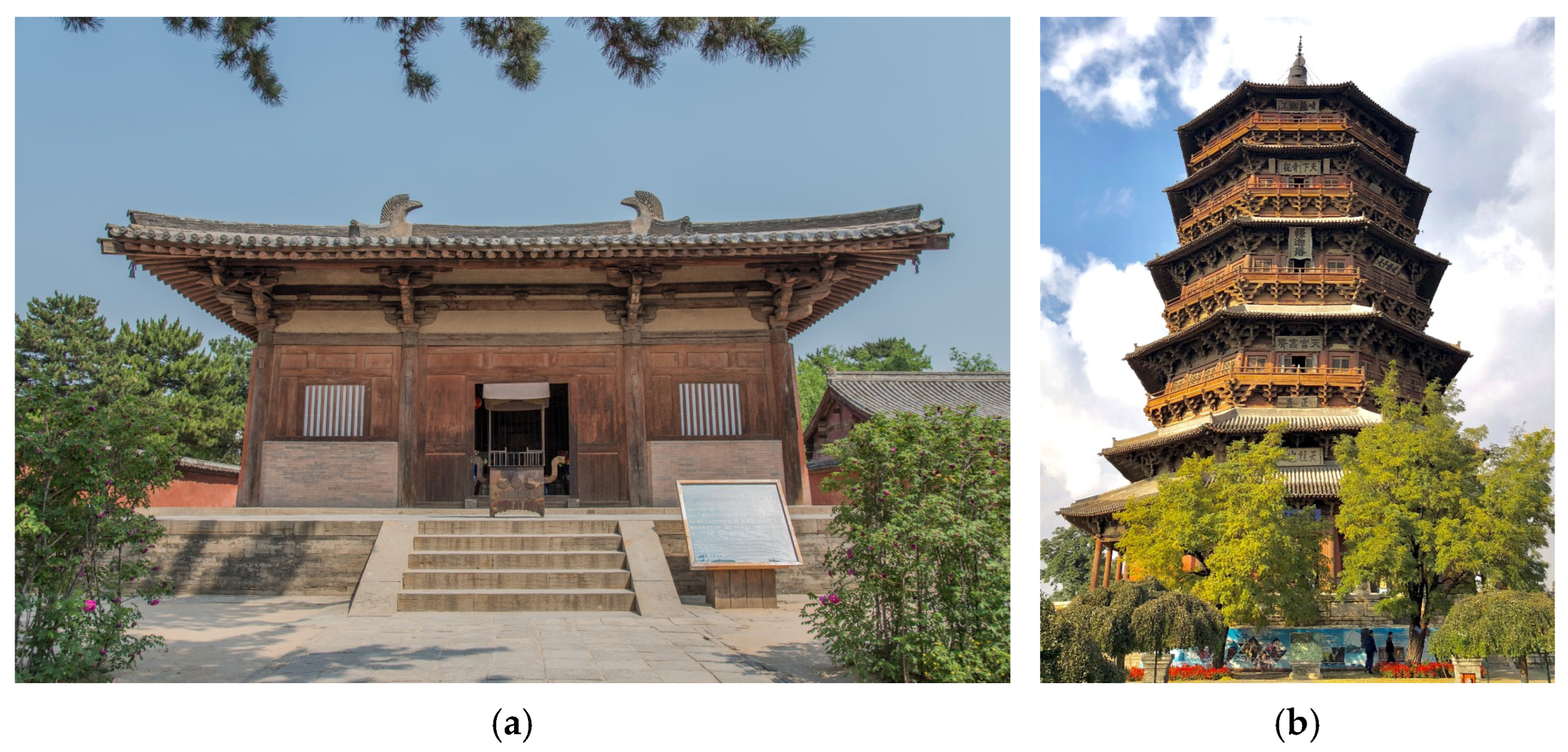
Ancient wooden structures, as an indispensable part of ancient architectural heritage, are endowed with a long evolutionary history, profound cultural connotations and sophisticated construction techniques and are therefore of important scientific, historical and cultural significance. Two representative historic ancient wooden structures, namely the Main Hall of the Nanchan Temple and the Yingxian Wooden Pagoda, are presented in Figure 1. The Yingxian Wooden Pagoda has a history of 970 years. It has been subjected to multiple earthquakes and wartime damage, resulting in inclination of the columns on the second floor and cracking and other defects in some structural components [1,2,3]. Nevertheless, the pagoda is still well preserved and remains standing, by which the prominent mechanical performance of ancient wooden buildings is adequately demonstrated.
The components of the ancient wooden structures can be classified into bracket sets (often known as dougong in Chinese) and wooden frames according to their structural composition. As a unique structural form of Chinese ancient wooden buildings, bracket sets are employed to support the loads of upper overhanging eaves and floor slabs, while wooden frames are integrated into the main architectural space through the connection of beams, columns and other members via mortise-tenon joints. Regarding the functional performance of bracket sets and wooden frames in ancient wooden structures, especially their seismic resistance capacity, comprehensive investigations have been widely conducted through model tests and numerical simulations [1,4,5,6,7,8]. It is indicated that in composite ancient wooden structures, small horizontal deformation is generated in bracket sets owing to their high horizontal stiffness, whereas greater deformation is induced in wooden frames, and structural damage is primarily concentrated at the mortise-tenon joints of wooden frames. Accordingly, the seismic performance of ancient wooden structures is significantly dominated by wooden frames assembled with beam-column mortise-tenon joints.
To reveal the hysteretic behavior of the mortise-tenon joints, many researchers have conducted various cyclic loading experiments on different types of joints and have derived their damage patterns and the inherent load-bearing mechanism [9,10,11,12,13]. The gap between the mortise and the tenon induced by the shrinkage of the wood after hundreds of years of service has negative effects on structural safety and has also been widely investigated in recent years [14,15,16,17,18]. In addition, in the traditional residential dwellings, the influence of infilled masonry or wooden walls on the seismic behavior of the frame with mortise-tenon joints has been studied through experiments [19,20,21].
Based on the test experiments of the mortise-tenon joints, some researchers have theoretically derived the hysteretic curves of the joints with considerations of their complicated loading states, nonlinear material properties and mutual contact status, and the theoretical curves can capture the main nonlinear mechanical characteristics of the joints well [16,22,23,24,25]. The finite element model with the solid element mesh can accurately depict the nonlinear behavior of the material and the geometrical morphology of each component of the mortise-tenon joints [26,27], but the computational cost needs to be reduced and the non-convergence problems should be overcome, especially for the complicated models. Therefore, some simplified models have also been proposed to simulate the performance of the mortise-tenon joints under lateral cyclic loadings, and the output results are in good agreement with the test results [28,29]. In addition, to calibrate the mechanical parameters in the hysteretic models, the support vector regression method and optimization algorithm have been validated [30,31].
During decades or even centuries of service, mortise-tenon joints of the wooden structures have been subjected to various forms of damage, such as insect infestation and corrosion, resulting in severe degradation of their mechanical performance. Accordingly, scholars have proposed a variety of reinforcement measures, including wooden insertion [32], steel jacket [33,34], self-tapping screw [35,36], shape memory alloy wires [37,38], friction dampers [39,40], etc. Moreover, the viscoelastic damper (VED) is another effective device that can prominently enhance the seismic performance of the mortise-tenon joints, and its multiple structural configurations can adapt to the spatial and installation limitations of different joints [41,42,43,44]. The matrix material of the VED is key to its mechanical properties. Nitrile butadiene rubber is a high-quality damping material, and the nitrile butadiene rubber-based viscoelastic damper (NVED) has been proven effective in enhancing the seismic resilience of the structures [45,46,47,48]. On this basis, the influence of the NVED on the cyclic behavior of the mortise-tenon joints is crucial to its engineering application and has therefore been investigated in this study.
In this study, the NVED is proposed to enhance the hysteretic behavior of the traditional Chinese mortise-tenon joints with two types of configurations, i.e., with and without the shear key. The mechanical performance of the NVED was tested considering the influence of the loading amplitude and the loading frequency. Then, four mortise-tenon joint specimens, two of which were reinforced with the NVED, were tested under cyclic loading to obtain their hysteretic behaviors and clarify the strengthening effect of the NVED. Based on the test results, a simplified simulation method for both the joint and the NVED was proposed and proved to be accurate. The proposed simplified simulation method can be used in the establishment of the numerical model of whole wooden structures to analyze their lateral performance when subjected to earthquakes, and therefore the reinforcing effect of the NVED can be investigated based on the seismic performance of whole structures.

2. Test Model and Program

2.1. Test Model

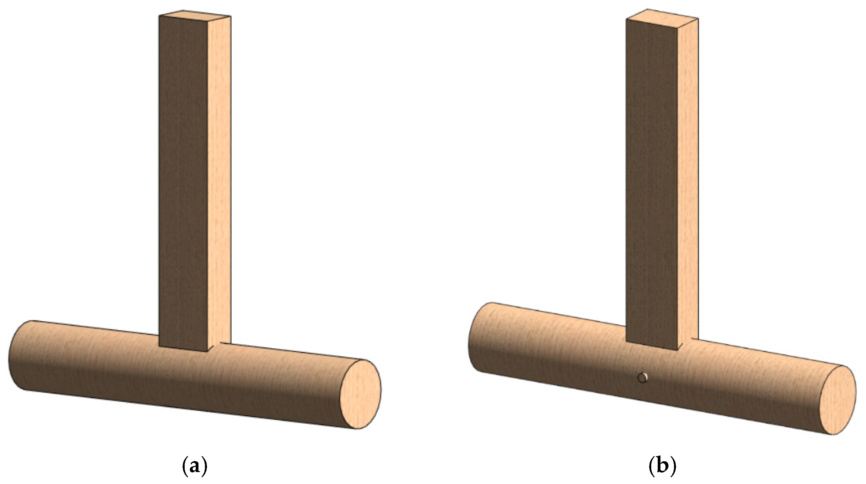
To conduct the experiments of the mortise-tenon joint with and without the installation of the NVED, a prototype mortise-tenon joint is selected from the ancient building code yingzafashi [49], which covers the specifications of wooden structures in the Song dynasty (960–1279 AD). The configurations of the selected mortise-tenon joint are presented in Figure 2, which are composed of a column with a circular cross-section and a beam with a rectangular cross-section. In Figure 2b, a round rod is inserted through the mortise of the column and the tenon of the beam serving as a shear key, which is commonly used in ancient buildings to tighten mortise-tenon joints. Therefore, this mortise-tenon joint with the shear key could be firmer than that without the shear key in Figure 2a. For simplicity, the joint model in Figure 2a is termed JM1 in the following content, while the joint model with the shear key in Figure 2b is labeled as JM2, and the only difference between these two models is the existence of the shear key.
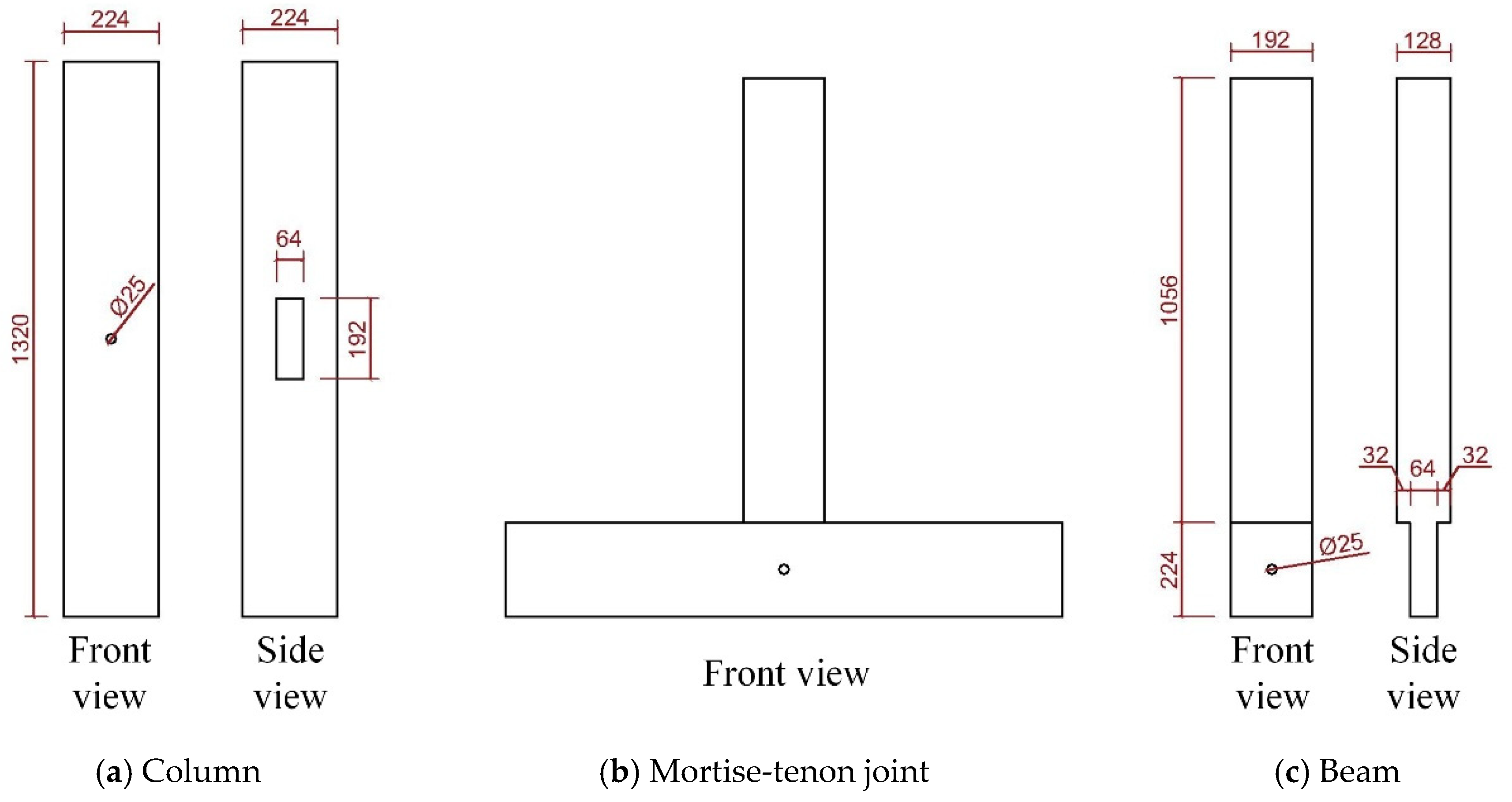
The dimensions of the two models are identical, including the mortise and the tenon, and are presented in Figure 3. The column has a length of 1320 mm and a circular cross-section with a radius of 112 mm, while the beam is 1280 mm in length and its rectangular cross-section has dimensions of 192 mm × 128 mm. The width of the tenon is half that of the beam, namely 64 mm, while its height is identical to that of the beam. A hole with a diameter of 25 mm is at the same position on both the beam and the column accommodating the installation of the shear key.

2.2. Material Properties

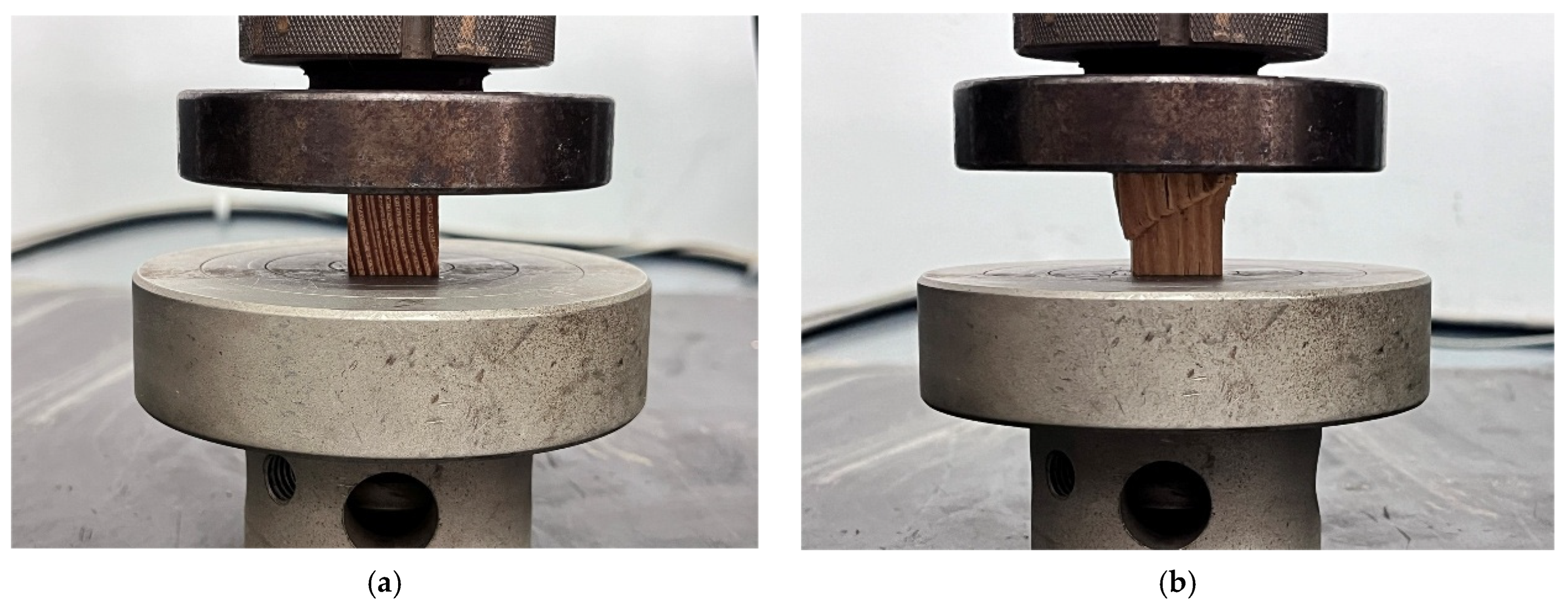
The selected mortise-tenon joint specimens were fabricated from Larix gmelinii, which was widely used in the construction of ancient wooden buildings in North China. In accordance with Chinese national test standards [50], the compressive mechanical properties of wood in three mutually perpendicular directions, namely longitudinal, radial and tangential, were measured, as presented in Figure 4. As summarized in Table 1, the longitudinal compressive elastic modulus parallel to the grain reaches 2980 MPa, while the elastic moduli in the two transverse directions are similar, with an average value of approximately 500 MPa. The corresponding compressive strengths in the longitudinal, radial and tangential directions are 70.3 MPa, 6.1 MPa and 13.6 MPa, respectively. Evidently, the longitudinal compressive strength is the highest among the three directions, and the radial compressive strength is roughly half of the tangential counterpart.

2.3. Mechanical Behavior of the NVED

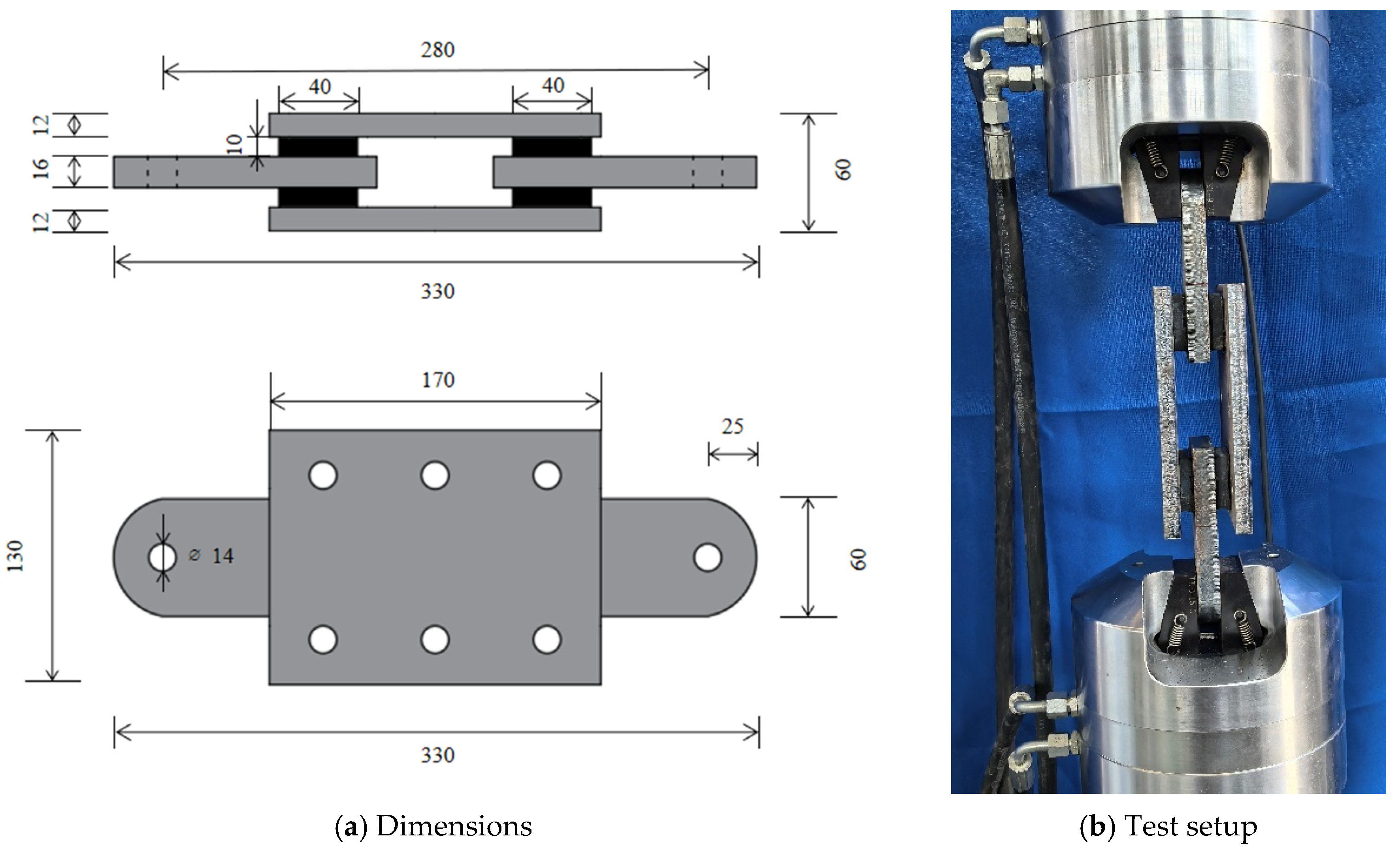
The NVED adopts the configuration illustrated in Figure 5a. Each damper consists of two inner steel plates, two outer steel plates and four identical rubber sheets. The two inner steel plates are arranged in a straight line. Two rubber sheets are bonded to both sides of each inner plate, and the outer sides of the rubber sheets are connected to the outer steel plates. Each rubber sheet has a planar dimension of 50 mm × 40 mm and a thickness of 10 mm, while the two outer steel plates are 170 mm × 130 mm in size with a thickness of 12 mm. The inner steel plates, with a thickness of 16 mm, feature a circular arc at one end and are drilled with a 14 mm diameter bolt hole for the fixation of the NVED. The length between the two bolt holes of the two inner steel plates is 280 mm.
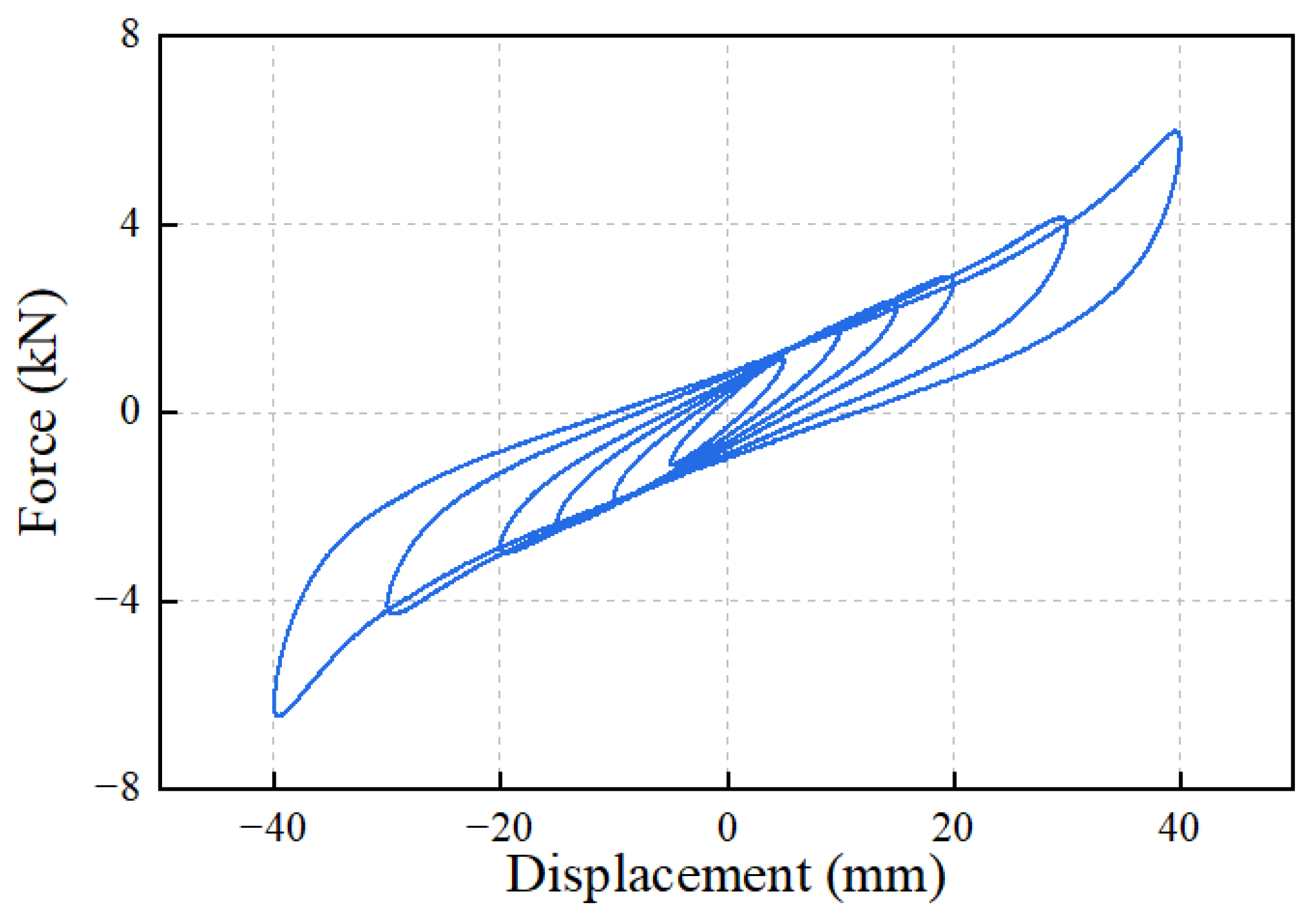
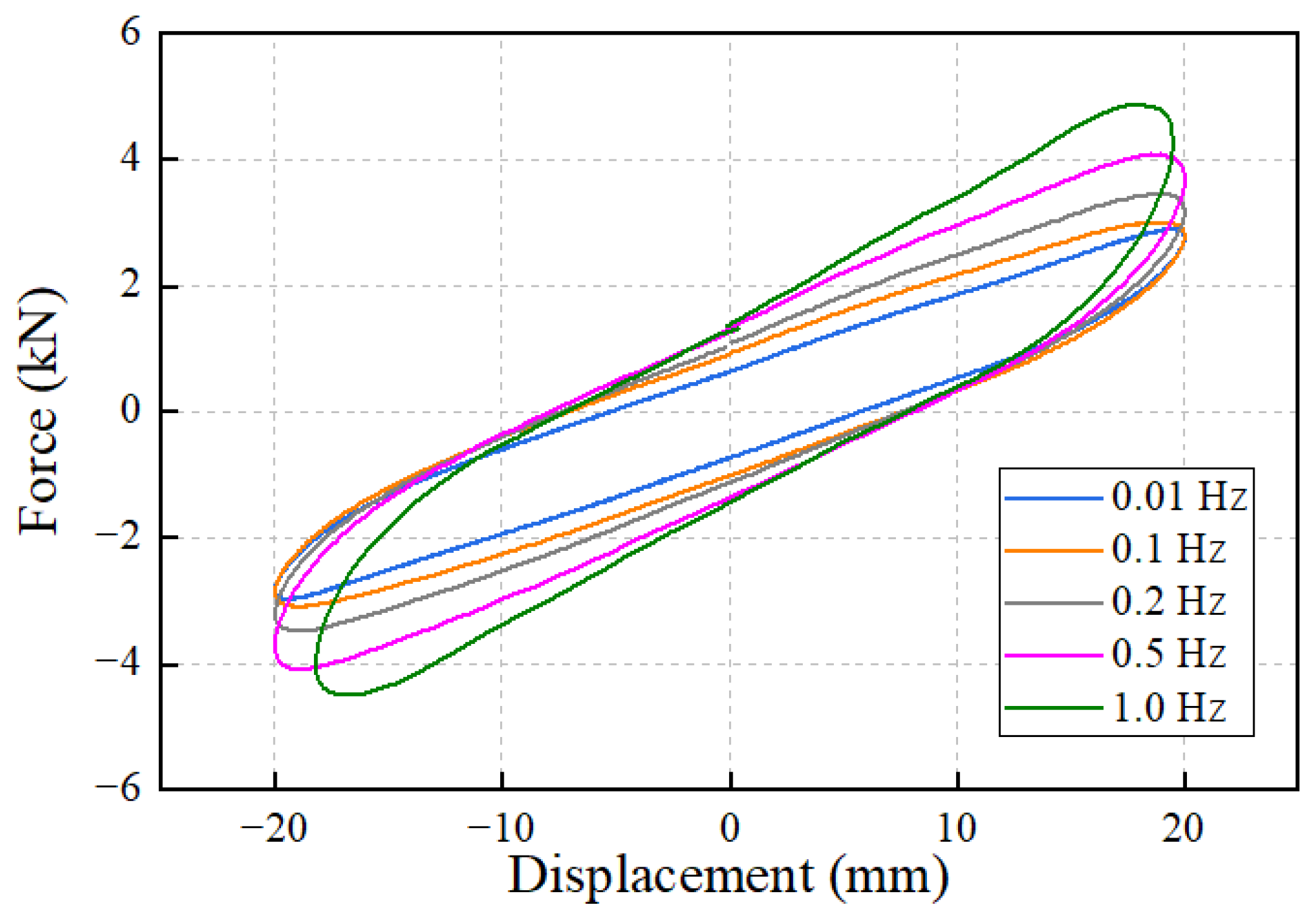
To investigate the mechanical performance of the NVED, cyclic loading tests were conducted under different loading amplitudes and loading frequencies, as shown in Figure 5b. When exploring the effect of loading amplitude, the loading frequency was fixed at 0.01 Hz, and the applied amplitudes were 5 mm, 10 mm, 15 mm, 20 mm, 30 mm and 40 mm, corresponding to the rubber shear strains of 25%, 50%, 75%, 100%, 150% and 200%, respectively. For the tests under various loading frequencies, the loading amplitude was kept constant at 20 mm (i.e., a shear strain of 100% for the rubber sheets), and the loading frequencies were set as 0.01 Hz, 0.1 Hz, 0.2 Hz, 0.5 Hz and 1 Hz.
Figure 6 presents the hysteretic curves of the NVED under different loading amplitudes. It can be observed that the hysteretic loops remain approximately elliptical when the loading amplitude is no more than 20 mm. As the loading amplitude further increases, the hysteretic loops exhibit obvious hyperelastic characteristics. The maximum damping forces under various loading amplitudes are summarized in Table 2, where each value is taken as the average of the peak forces obtained in the positive and negative loading directions.
Figure 7 illustrates the hysteretic loops of the NVED under different loading frequencies. It can be seen that the hysteretic loops corresponding to 0.01 Hz and 0.1 Hz are generally similar, while the damping force and the dissipated energy represented by the loop-enclosed area at 0.1 Hz are slightly greater than those at 0.01 Hz. With the increase in the loading frequency, the maximum damping force rises rapidly, and the dissipated energy of each loop gradually increases as well. This indicates that the energy-dissipating capacity of the NVED is significantly affected by the loading frequency. It should be noted that when the loading frequency reaches 1 Hz, the test machine operates at a high speed with a large deformation, resulting in minor deviations in loading displacement, which is attributed to the limitations of the test machine. The maximum damping forces at different loading frequencies are listed in Table 3. It is evident that the maximum damping force increases sharply with the rise in loading frequency.
Although the dependencies of the NVED on the loading displacement and frequency have been preliminarily tested herein, the long-term applicability of the damper should be further investigated in the future since the long-term durability and environmental sensitivity of the viscoelastic material may have strong influences on the mortise-tenon joints reinforced with the damper.

2.4. Test Program

To compare the influence of the NVED on the hysteretic performance of the mortise-tenon joints, two JM1 specimens and two JM2 specimens were fabricated based on the configurations and dimensions presented in Figure 2 and Figure 3. During the fabrication process of the four specimens, the grain direction of the wood of the beam and column runs along the longitudinal direction of the two components. That is to say, the center of the growth-ring almost coincides with the center of the components in their sectional planes. To avoid the influence of the natural defects (such as knots) of the wood material on the hysteretic response of the joints, the mortise and tenon parts of the joints are selected with a clear surface during the fabrication process.
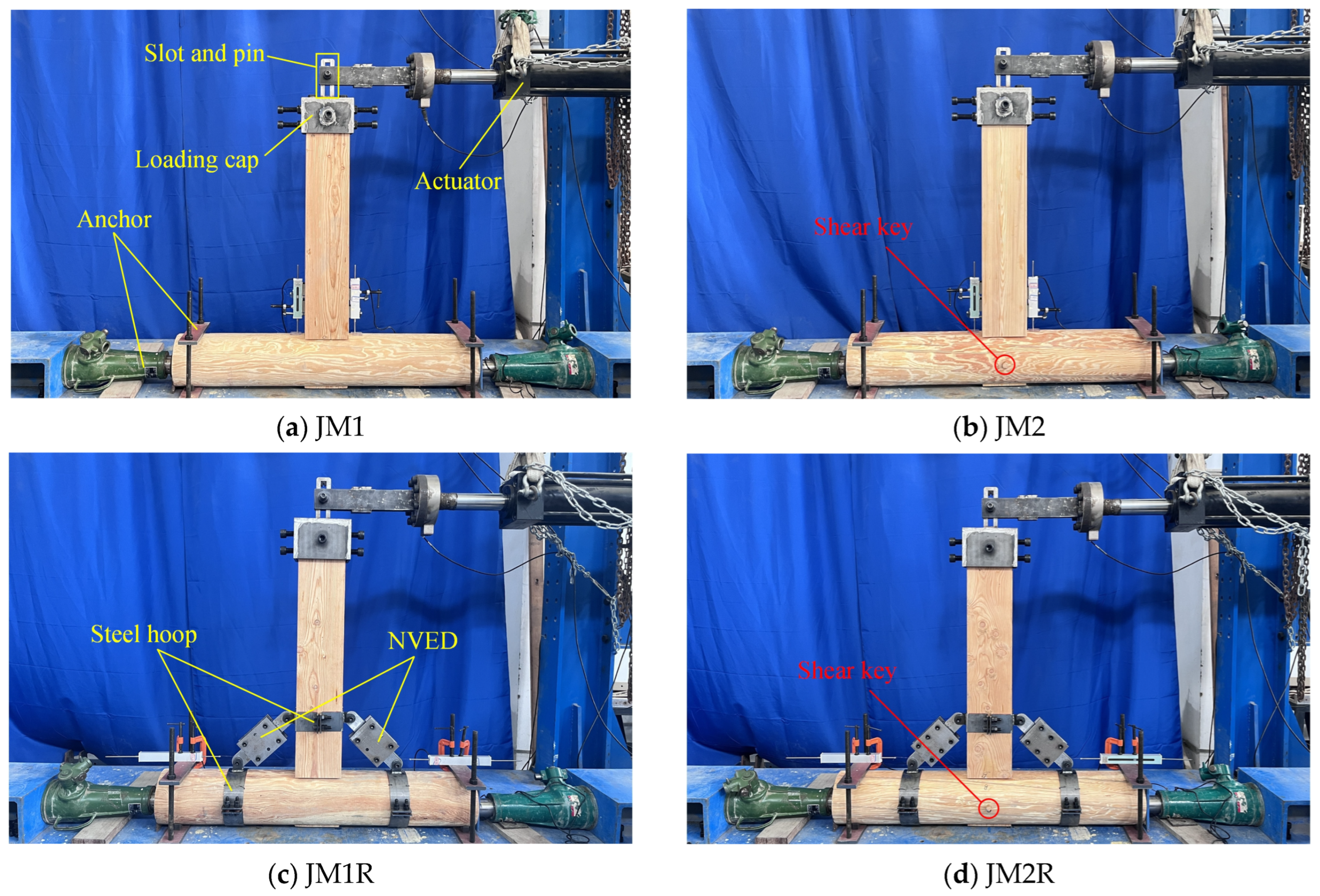
Firstly, the quasi-static cyclic loading tests were conducted on the original JM1 and JM2 specimens without the installation of the NVED. The test setup of these two specimens is presented in Figure 8a,b for illustration. It can be seen from the figure that the column was placed horizontally on the ground for the convenience of loading. Vertical and horizontal anchors were applied at both ends of the column to guarantee its stability throughout the test. Meanwhile, the beam was arranged vertically, with its lower end inserted into the column to form the mortise-tenon joint, and a loading cap was mounted on the top of the beam. The loading cap was equipped with a sliding slot, in which a pin shaft connected to the horizontal actuator was set. The diameter of the pin shaft was nearly equal to the width of the sliding slot, and therefore the pin shaft can exert horizontal force to push or pull the loading cap when the horizontal actuator moves back and forth. During the tests, relative sliding between the pin shaft and the sliding slot could accommodate the vertical displacement of the end of the beam caused by the rotation of the mortise-tenon joint.
Furthermore, quasi-static cyclic loading tests were carried out on the JM1 and JM2 specimens reinforced with the NVED, and the two specimens with the dampers are therefore termed JM1R and JM2R, respectively. Figure 8c,d displays the test setup of the two reinforced specimens. The columns of the JM1R and JM2R specimens were equipped with two circular steel hoops, and one square steel hoop was installed on the beams. The steel hoops are customized to fit the beam and the column, and they are connected to the wooden components by bolts and nuts; therefore, the installation of the NVED is unlikely to cause any damage to the mortise-tenon joints. Still, in the practical implementation, the installation of the steel hoops and the dampers should be carefully dealt with to avoid potential damage to the wooden components. As illustrated in the figure, two NVEDs were symmetrically installed on the two sides of the beam. The inner steel plates at both ends of each NVED were bolted to the steel hoops on the beam and the column, and each NVED was installed at an angle of 45° to both the horizontal and vertical directions. Except for the installation of the NVED, the other test setups of the JM1R and JM2R specimens remained consistent with those of the original JM1 and JM2 specimens shown in Figure 8a,b.
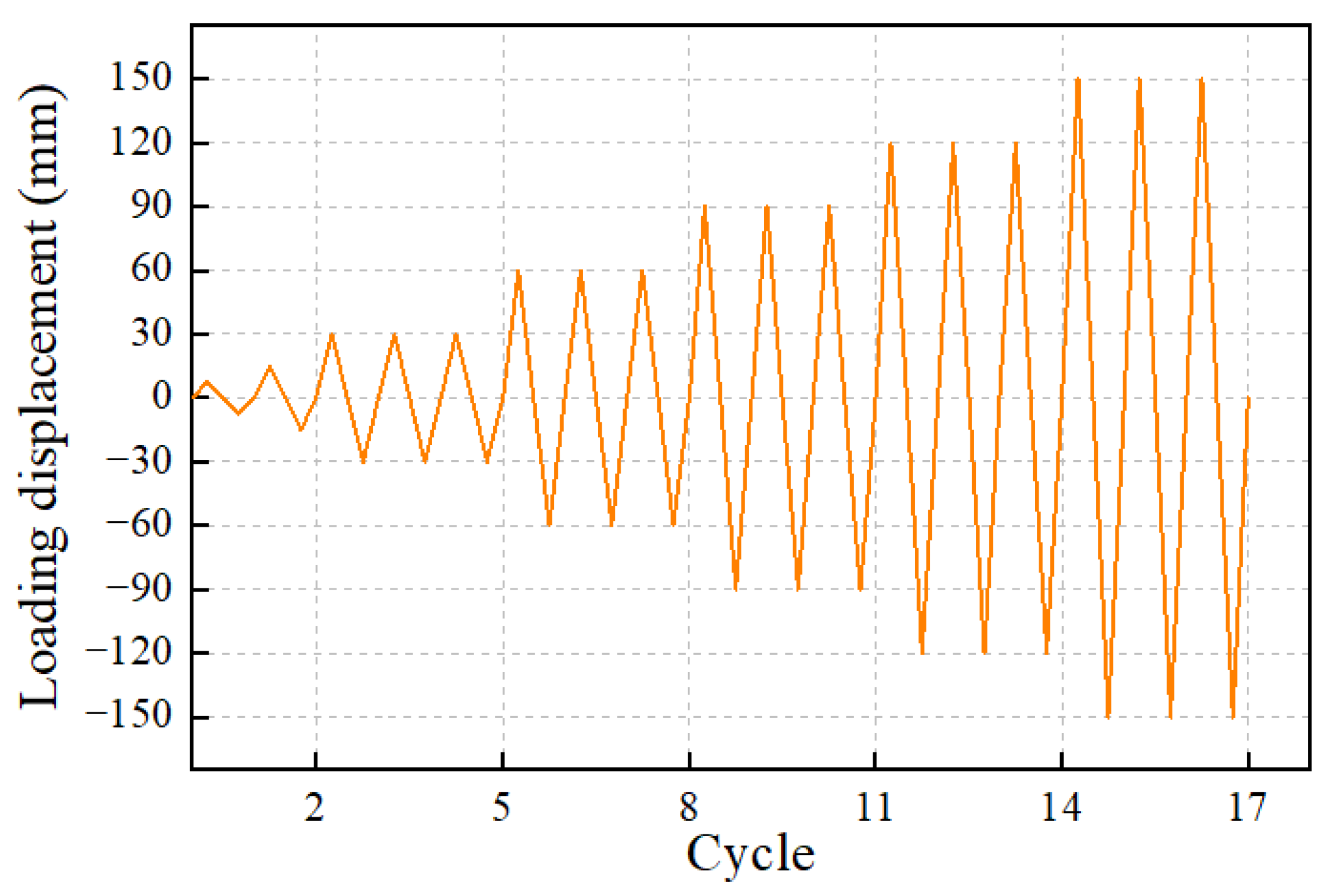
In accordance with the ISO 16670 standard [51], quasi-static cyclic loading was applied to the four mortise-tenon joint specimens following the displacement-controlled loading protocol depicted in Figure 9. The traditional jointed wooden structures possess great deformation capacity and can accommodate large lateral deformation before collapse under earthquakes. For example, the maximum inclination angle of the column in Yingxian Wooden Pagoda is up to 10.23 degrees. Considering that the loading capacity of the hydraulic actuator is 200 mm, a loading amplitude of 150 mm is selected to derive the mechanical properties of the joints to a greater extent. Initially, the mortise-tenon joint specimens were subjected to one loading cycle each at displacement amplitudes of 5% and 10% of the maximum displacement amplitude, corresponding to 7.5 mm and 15 mm, respectively. Subsequently, cyclic loading was conducted for three cycles at each of the displacement amplitudes of 30 mm, 60 mm, 90 mm, 120 mm, and 150 mm, aiming to capture the characteristics such as mechanical degradation of the mortise-tenon joints after loading-induced damage. During the loading process, the displacement and load applied to the specimens were measured using the displacement and force sensors integrated with the actuator so as to obtain the load–displacement hysteretic curves.

3. Test Results and Discussion

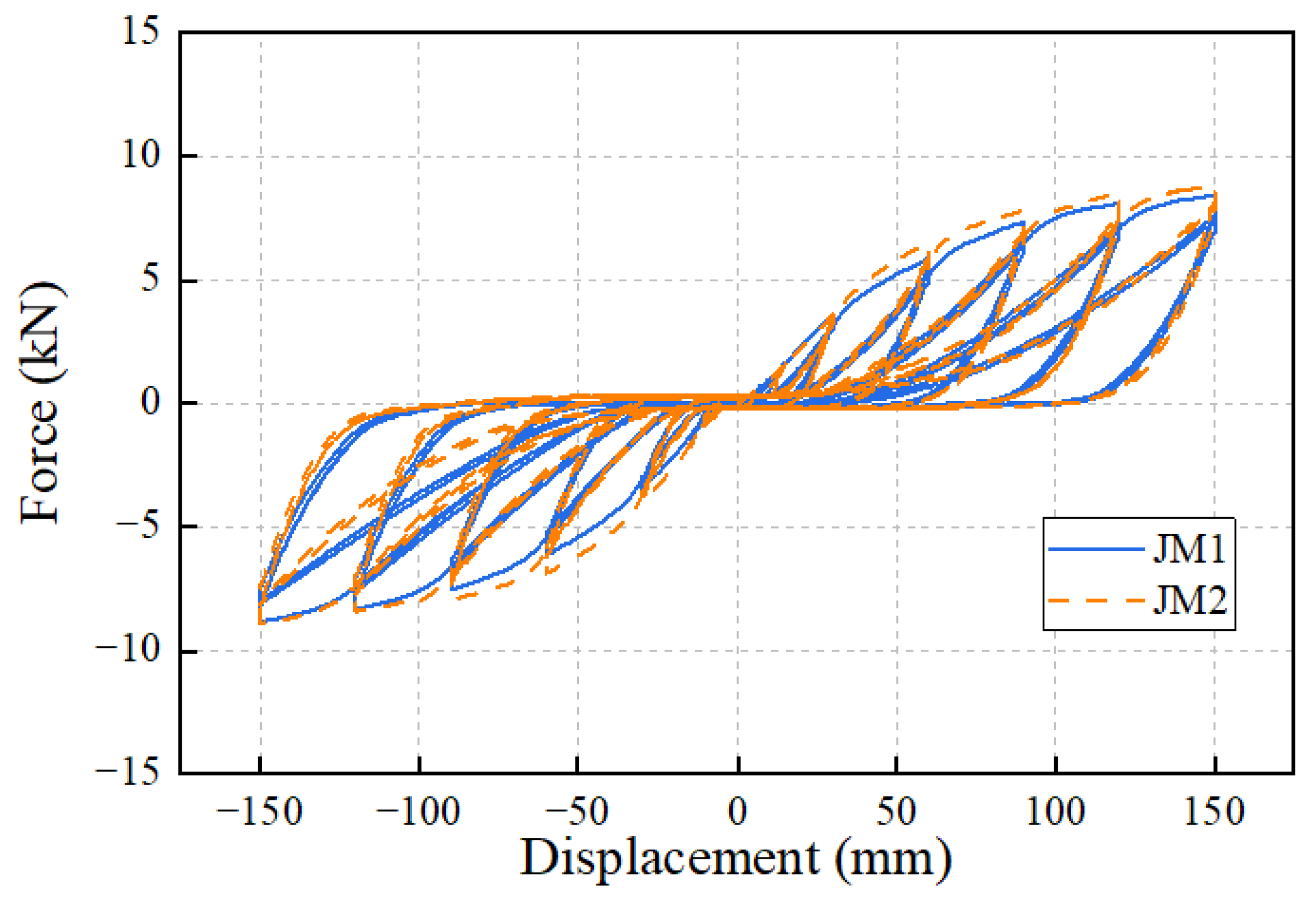
Figure 10 presents the load–displacement hysteretic curves of two original mortise-tenon joint models (JM1 and JM2) without the installation of the NVED, namely the models with and without the shear key. Both joints demonstrate the same damage mode, namely the local embedment of the tenon. As for the mechanical behavior, it can be observed from the figure that the hysteretic curves of the two types of models exhibit the same shape and variation trend, and the load of the JM2 model with shear key is slightly higher than that of the JM1 model. This indicates that the influence of the shear key on the hysteretic performance of the mortise-tenon joints is relatively limited. Neither of the two types of curves in the figure shows a descending segment, and their loads at a loading displacement of 150 mm are approximately 8.6 kN and 8.8 kN, respectively. In addition, the load values during the first loading cycle at each displacement amplitude are higher than those during the second and third cycles at the same amplitude, while the hysteretic loops of the second and third cycles are almost consistent. This is because new damage occurs in the mortise-tenon joints after the first loading cycle, while the second loading cycle at the same amplitude barely induces further damage; thus, the hysteretic loop of the third cycle is almost the same as that of the second cycle. Therefore, in the subsequent discussion on skeleton curves, stiffness, and dissipated energy, only the results of the first and second cycles under the same loading amplitude are presented. In addition, slight asymmetry can be observed in the positive and negative loading directions, which can be attributed to the fabrication and installation differences and is frequently observed in the hysteretic curves of wooden joints [14,16,19].
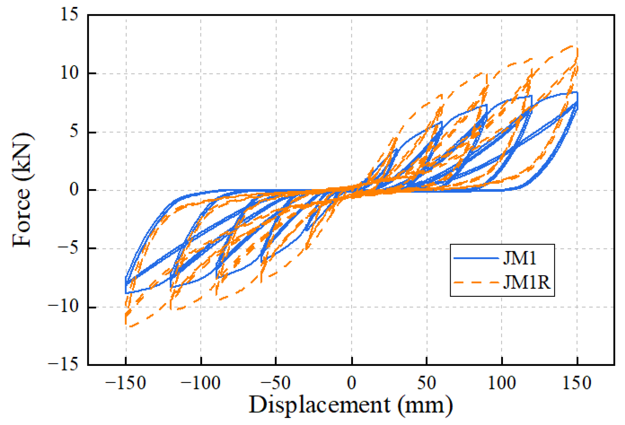
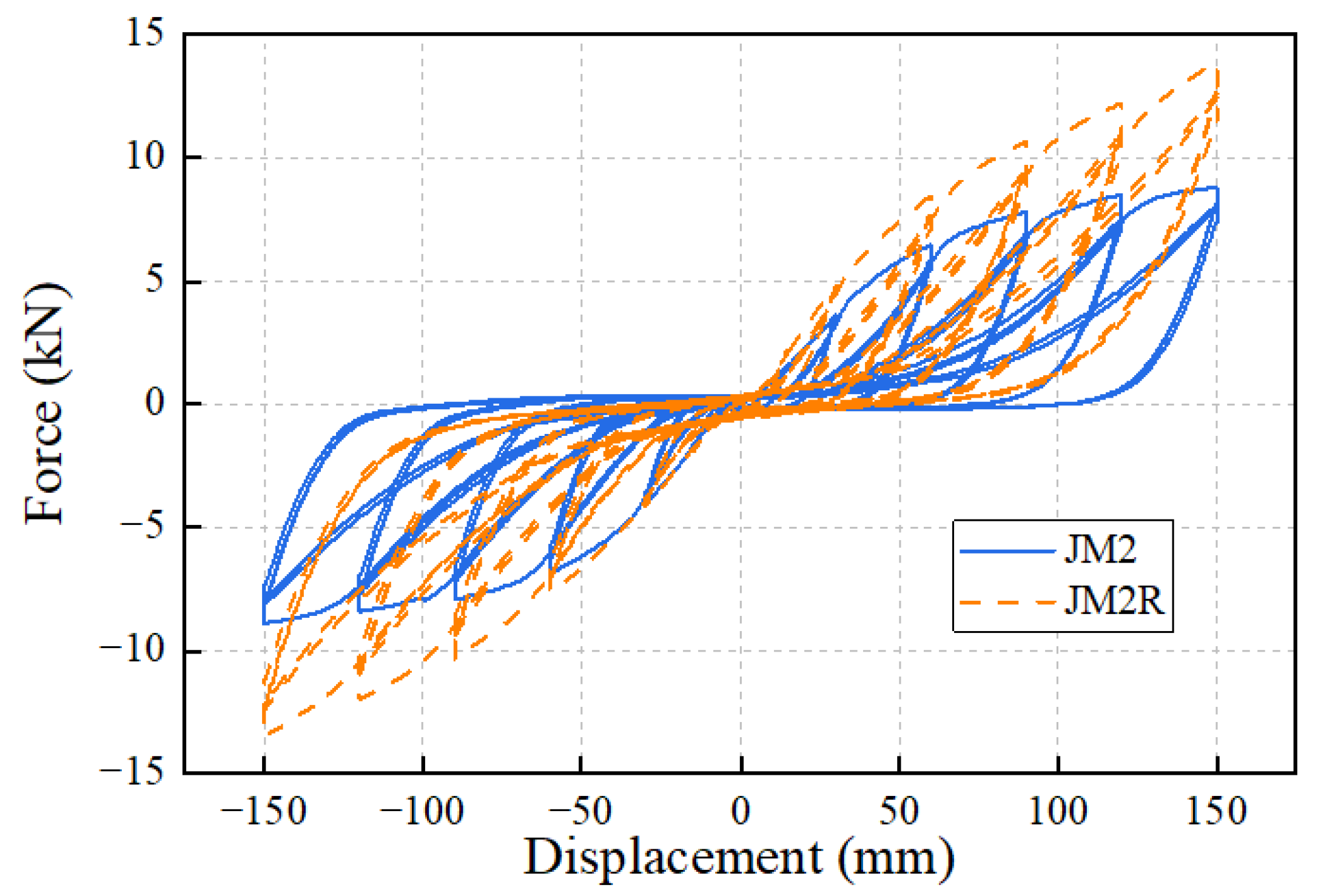
To compare the effect of the NVED on the mechanical performance of the mortise-tenon joints, Figure 11 and Figure 12 present the hysteretic curves of the JM1 and JM2 models with and without the NVED, respectively. It can be observed from the figures that the installation of the dampers significantly increases the loads of both mortise-tenon joint models; meanwhile, the energy dissipation capacity represented by the area enclosed by the hysteretic loops is also greatly improved. As shown in Figure 10, the load of the original mortise-tenon joints is almost zero when the displacement is around 0 mm. However, after the installation of the NVED, there is a certain load value in the hysteretic curves of both models even at a displacement of 0 mm, which is because the NVED can enhance the load of the mortise-tenon joints over the entire loading amplitude range. In addition, it can be seen from the figures that the hysteretic loops of the second cycle at the same amplitude for the mortise-tenon joints reinforced with the NVED are also larger than those of the original models.
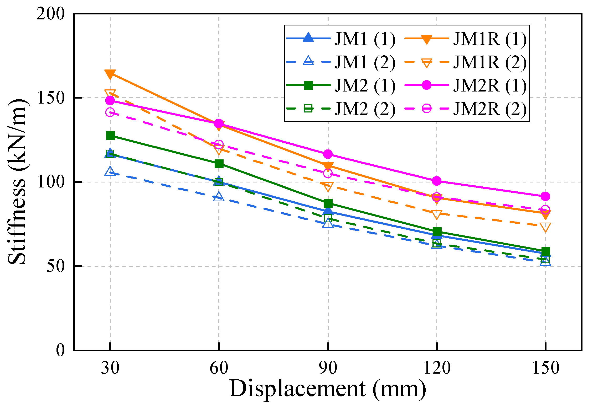
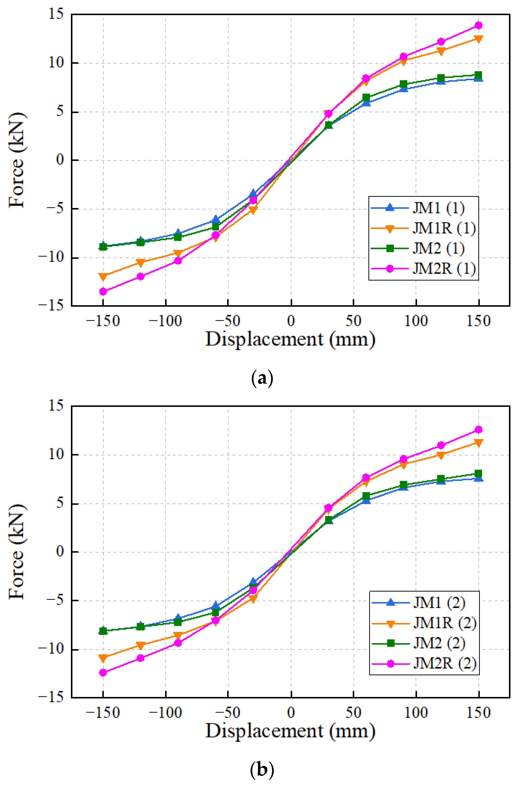
Figure 13 presents the skeleton curves of the four test models, and the numbers 1 and 2 in parentheses in the legend indicate the loads obtained from the first or the second loading cycle at different displacement amplitudes. The four curves in these two figures exhibit the same variation characteristics. The skeleton curves of the JM2 model are relatively close to those of the JM1 model. After the installation of the NVED, the loads of the JM2R model and the JM1R model are relatively close when the displacement amplitude is not larger than 60 mm. However, when the displacement amplitude exceeds 60 mm, the load of the JM2R model is higher, and the gap between the two curves gradually increases with the increase in the displacement amplitude. When the displacement amplitude reaches 150 mm, the loads of the JM2R model and the JM1R model are 13.9 kN and 12.6 kN, respectively, while the loads of the JM2 model and the JM1 model are 8.8 kN and 8.6 kN, respectively. This indicates that the installation of the NVED can increase the loads of the mortise-tenon joint models by 58% and 47%, respectively, at a displacement of 150 mm.
By comparing the skeleton curves of the models with and without the NVED, it can be observed that when the displacement amplitude exceeds 60 mm, the loads of the JM1 and JM2 models without dampers increase slowly and tend to be stable. In contrast, the loads of the JM1R and the JM2R models increase with the increase in the displacement amplitude when the displacement exceeds 60 mm, indicating that the NVED can effectively improve the load resistance capacity of the mortise-tenon joints under larger deformations.
Figure 14 presents the stiffness k Δ of the four mortise-tenon joint models at different loading amplitudes, whose values are the average of the stiffness in the positive and negative loading directions and are calculated by Equation (1). It can be observed from the figure that all curves show the same variation trend, which can be approximately regarded as decreasing linearly with the increase in the displacement amplitude. By comparing the stiffness changes in the mortise-tenon joints with and without the NVED, it can be seen that when the displacement amplitude is 30 mm, the installation of the NVED increases the first-cycle loading stiffness of the JM1 model from 117 kN/m to 165 kN/m, and the second-cycle stiffness from 106 kN/m to 153 kN/m, with an increase of more than 40% in both cases. When the displacement reaches 150 mm, the first-cycle stiffness of the JM1 model increases from 58 kN/m to 81 kN/m of the JM1R model, and the second-cycle stiffness from 52 kN/m to 74 kN/m, with an increase of 40% as well.
k Δ = F + Δ + F Δ + Δ + Δ
where Δ is the loading amplitude, +Δ and F are the maximum positive displacement and the corresponding force, and −Δ and F−Δ are the maximum negative displacement and the corresponding force.
For the JM2 model and the JM2R model, when the displacement is 30 mm, the installation of the NVED results in a relatively small increase in their first-cycle and second-cycle stiffness, approximately 20%. However, with the increase in displacement, the NVED leads to a rapid increase in the stiffness of the models. When the displacement reaches 150 mm, the stiffness of the JM2R model is increased by more than 40% compared with that of the JM2 model.
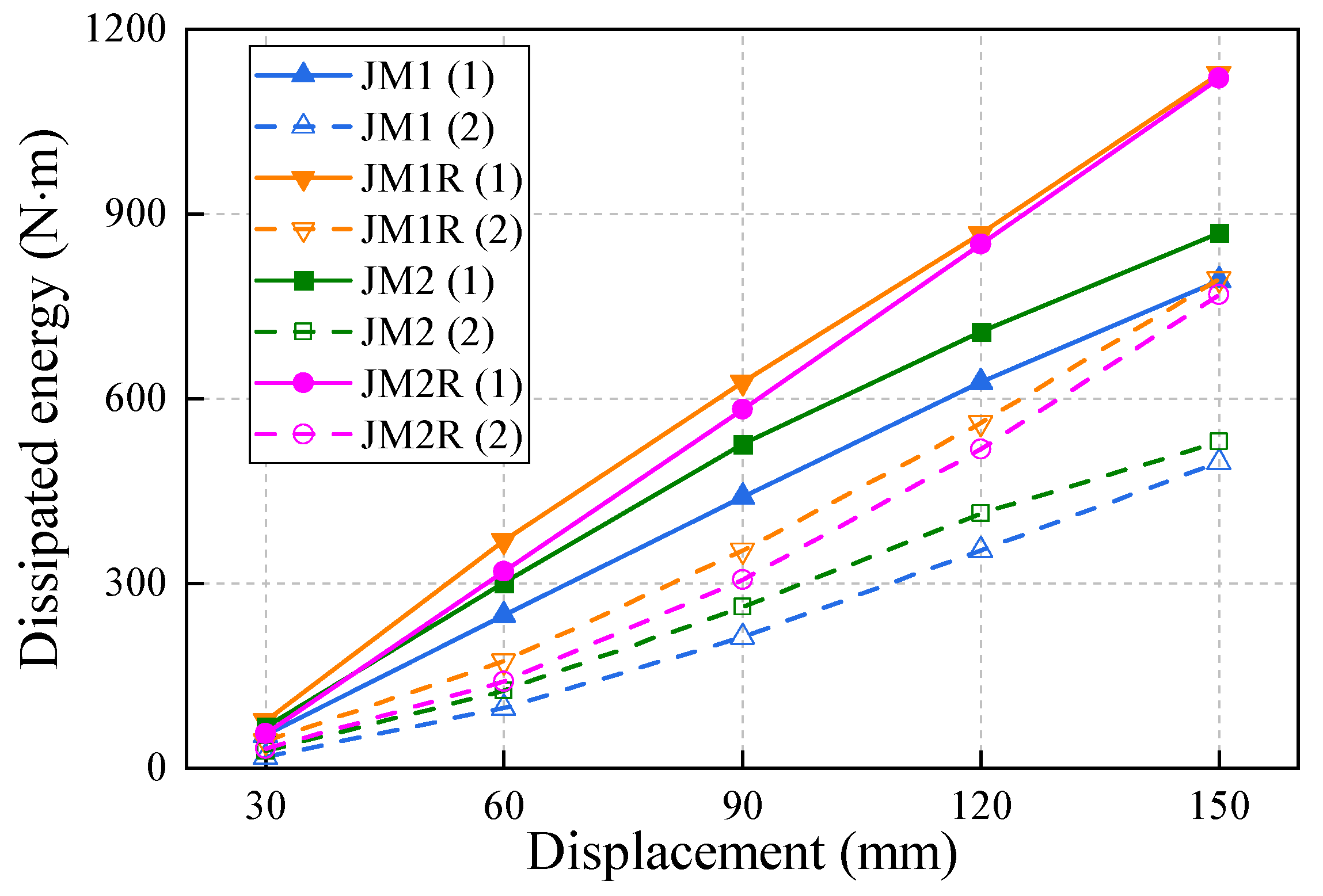
The energy dissipation results of the four models at different loading amplitudes are presented in Figure 15. The dissipated energy at each loading cycle is calculated by the enclosed area of the hysteretic loop. It can be seen that, on the whole, all curves approximately increase linearly with the increase in the loading amplitude. At different displacement amplitudes, the mortise-tenon joint models with the NVED exhibit the maximum energy dissipation in the first loading cycle, and the energy dissipation results of the JM1R model and JM2R model are relatively close. The dissipated energy of the JM1 and JM2 models in the first loading cycle is greater than that of the JM1R and JM2R models in the second loading cycle. This indicates that the increase in the dissipated energy caused by the NVED is less than the decrease in energy dissipation caused by the damage of the mortise-tenon joints, but the gap between the two is not significant. It can also be seen from the figure that with the increase in the displacement amplitude, the energy dissipated by the NVED increases rapidly, indicating that the dampers have greater energy dissipation capacity under large deformations.
The equivalent damping ratio is a key indicator reflecting the energy dissipation capacity of structures and can be calculated by Equation (2). In this equation, Ed is the dissipated energy computed by the enclosed area of the hysteresis loop, while SΔ+ and SΔ− respectively denote the area of the triangle formed by the origin, the point with the maximum or the minimum displacement in the hysteresis loop, and its projection point in the abscissa.
h e = E d 2 π ( S Δ + + S Δ )
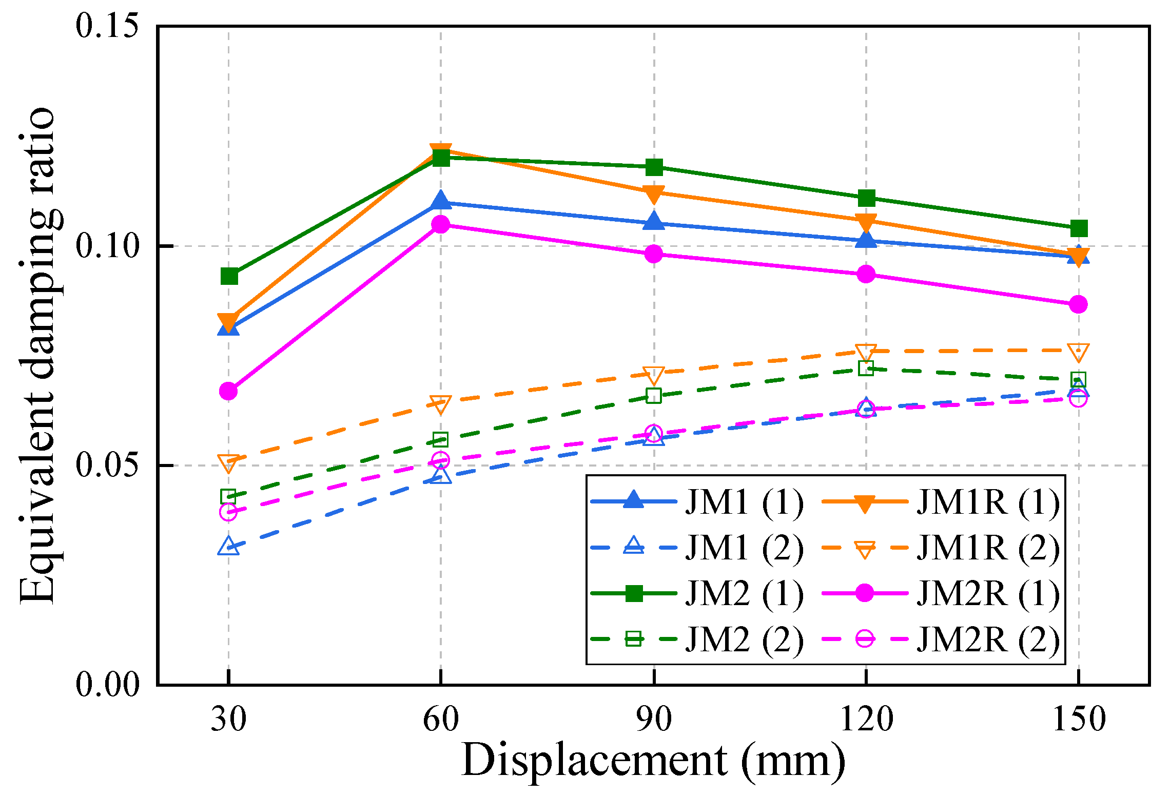
The corresponding equivalent damping ratios of the four models are plotted in Figure 16. It can be observed that the equivalent damping ratios of the four models derived from the first loading cycle exhibit the same variation trend, i.e., showing a variation characteristic of firstly increasing and then decreasing, and reaching a maximum value of more than 0.1 when the displacement amplitude is 60 mm. In contrast, the equivalent damping ratios of the four models from the second loading cycle show another characteristic, that is, gradually increasing with the increase in loading amplitude, and their values are approximately 0.07 when the displacement amplitude is 150 mm. According to Equation (2), the equivalent damping ratio not only relies on the dissipated energy enclosed in a hysteretic loop, but can also be affected by the loading displacement and the peak load, which are included in the denominator of the equation. Therefore, a comparison of the equivalent damping ratio results between the models with and without the NVED reveals that although the installation of the dampers can effectively increase the dissipated energy, the synchronous increase in load leads to the equivalent damping ratios of the reinforced models not completely exceeding those of the original models.
Based on the test results above, the installation of the NVED can significantly increase the stiffness and the dissipated energy of the mortise-tenon joint. Therefore, it can be deduced that when the NVED is installed in a complete frame system, the stiffness of the system can be enhanced, and thus the lateral deformation can be decreased. However, the exact effect of the NVED on the seismic performance of the complete frame structures should be investigated through shaking table tests, which will be conducted in further research.

4. Simplified Simulation Method

4.1. Simulation of the Mortise-Tenon Joint

It can be seen from the test results of the NVED and the mortise-tenon joints that both of them exhibit significant nonlinear effects. One dimensional analytical element has been proven to have a strong ability to simulate the behavior of different structures and their components [52,53]. Therefore, a simplified simulation analysis method of the mortise-tenon joint and the NVED is proposed herein based on the OpenSees platform. Since it is revealed from the comparison of the hysteretic behavior of the JM1 and JM2 models in Figure 10 that the shear key in the JM2 model shows little effect on the mechanical performance of the model, the mortise-tenon joint JM1 (without a shear key) and JM1R are simulated in this study.
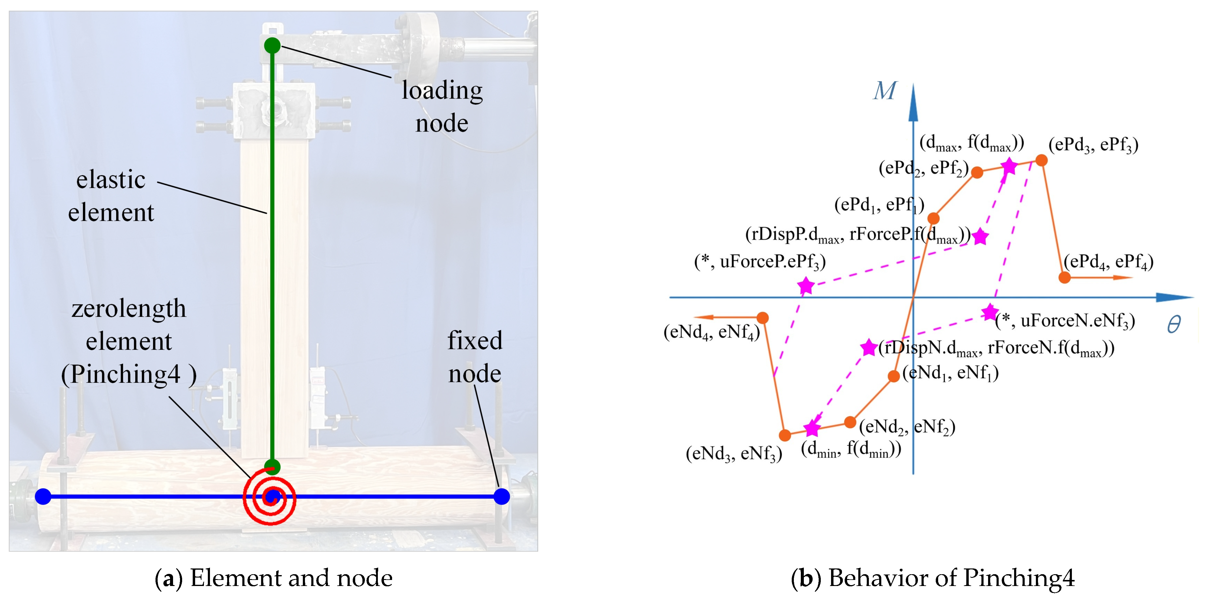
Figure 17a presents the simplified analysis model of the mortise-tenon joint JM1 without the installation of the NVED, where both the beam and column are simulated using elastic elements, and their mechanical parameters are calculated based on their cross-sectional dimensions given in Figure 3 and the material properties of wood listed in Table 1. Since the nonlinear mechanical performance of the mortise-tenon joint is mainly determined by the behavior between the tenon and the mortise, a zero-length nonlinear rotational spring is used to connect the corresponding nodes of the beam and column elements, and the Pinching4 material is adopted to characterize its moment-rotation relationship. Figure 17b shows the mechanical model of the Pinching4 material. It can be observed from the figure that the skeleton curve needs to be defined by the load–displacement curve, and the hysteretic rules need to be defined by other parameters.
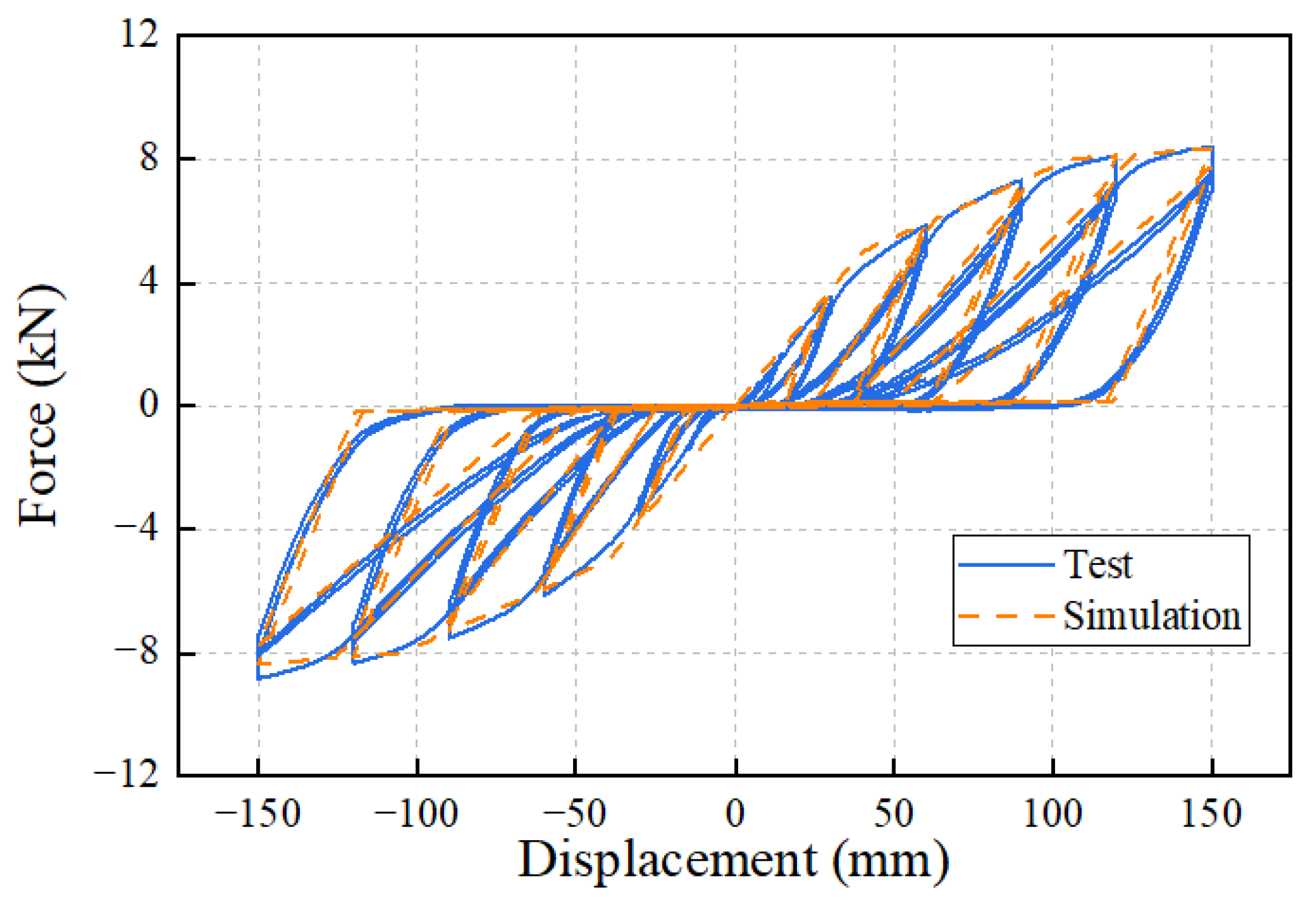
Based on the hysteretic curves and skeleton curves of the JM1 model, the parameters in the Pinching4 material were calibrated, and the same loading process as the test was carried out on this simplified model. The simulation results of the JM1 model are shown in Figure 18. For comparison, the test results of the JM1 model are also presented in the figure. It can be seen from the figure that the proposed simplified analysis model can accurately reflect the hysteretic characteristics of the JM1 model. In particular, the stiffness and strength degradation characteristics of the mortise-tenon joint in the second loading cycle can be accurately simulated by adjusting the hysteretic parameters of the Pinching4 material. In addition, the simplified model can also accurately reflect the significant pinching effect of the mortise-tenon joint.

4.2. Simulation of the NVED

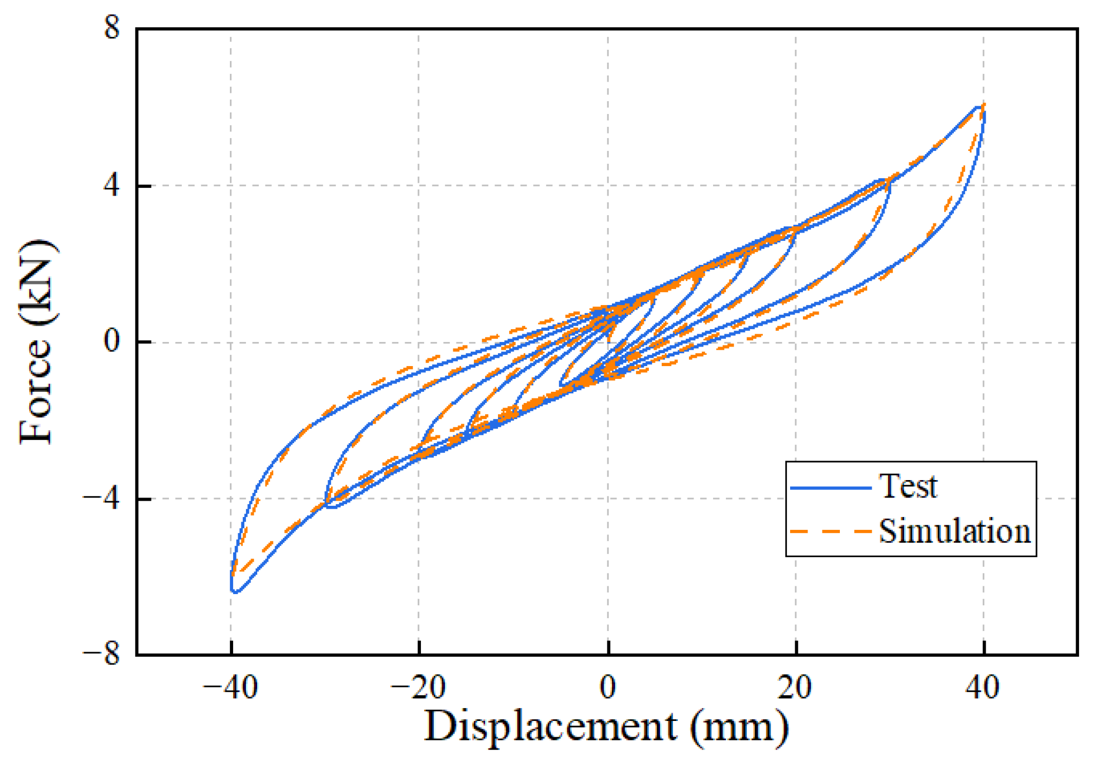
The KikuchiAikenHDR material model in OpenSees can accurately simulate the nonlinear hysteretic characteristics of high-damping rubber materials; therefore, this material model is adopted in this study to simulate the mechanical behavior of the NVED. This material model takes parameters such as rubber type, area, and thickness as inputs, and can adjust the mechanical parameters, including rubber shear modulus, equivalent damping ratio, and shear force ratio, at zero displacement by using several correction coefficients. Based on the NVED hysteretic curves obtained from Figure 6 in this study, the material parameters were calibrated, and the NVED simulation results are shown in Figure 19. It can be observed that the simulation results are in good agreement with the test results, especially when the displacement is not over 30 mm. When the displacement reaches 40 mm, due to a certain asymmetry of the curves in the positive and negative loading directions of the NVED, the load obtained by simulation is slightly smaller than the test results in the negative loading direction. However, in general, this material model can achieve a good simulation effect and can largely reflect the nonlinear characteristics of the NVED.

4.3. Simulation of the Joint Reinforced with the NVED

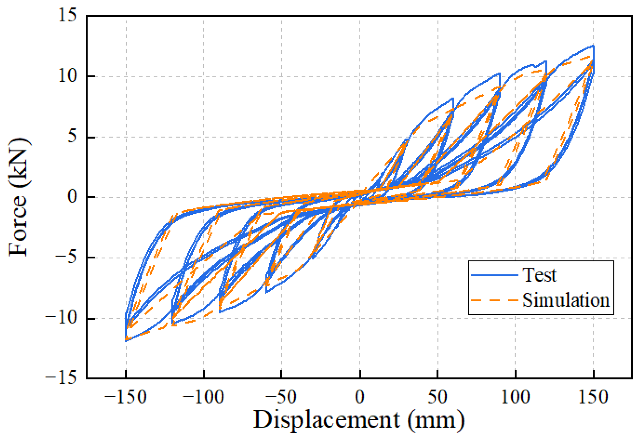
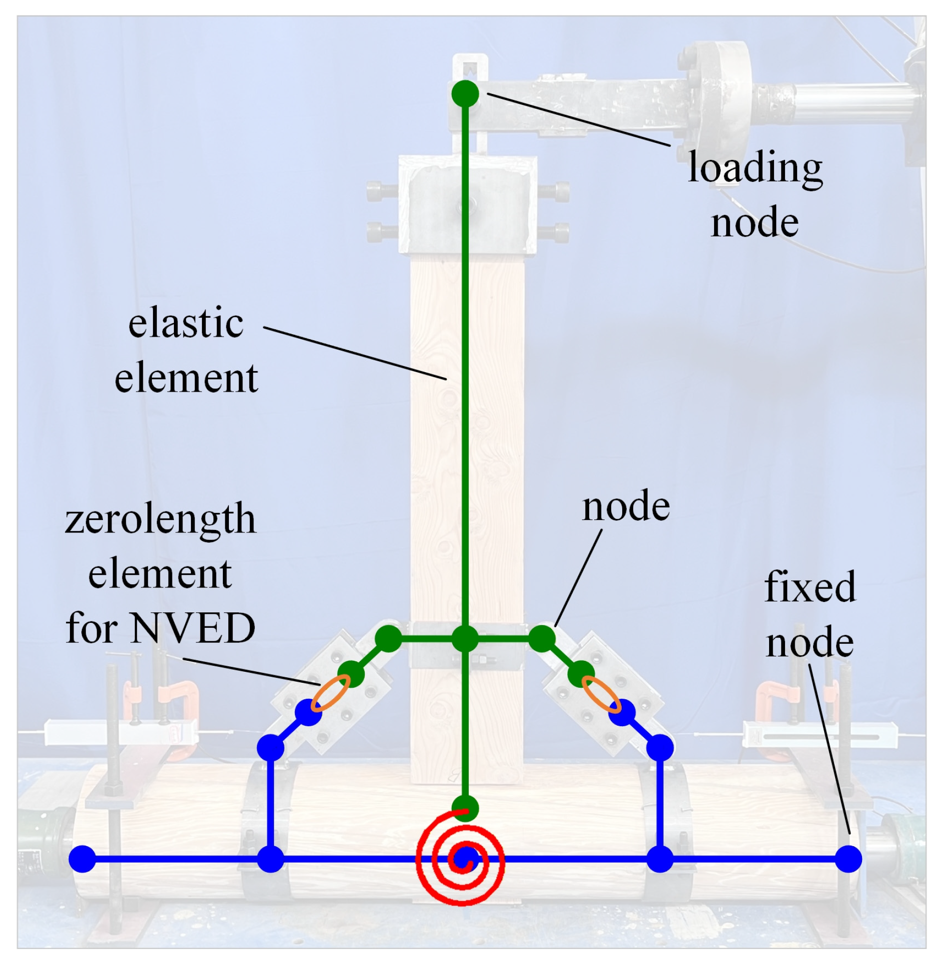
Based on the simplified model of the JM1 in Figure 17a, a zero-length element NVED was adopted to simulate the NVED, and the calibrated KikuchiAikenHDR material parameters were assigned to this element, resulting in the simplified model of JM1R as given in Figure 20. The installation position of the NVED in the figure is completely consistent with that in the test. The same loading process as the test was applied to this simplified model, and the simulation results of the JM1R model are presented in Figure 21 along with test results.
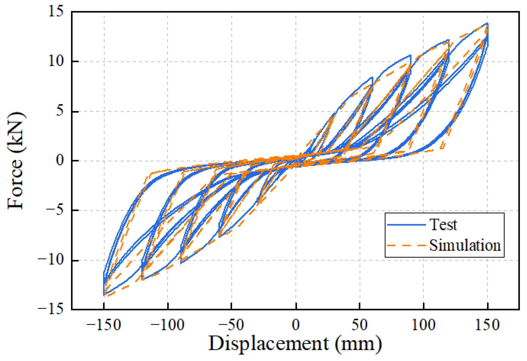
From the comparison between the simulated and test results of the hysteretic behavior of the JM1R model in Figure 21, it can be seen that the simplified analysis model can well reflect the hysteretic characteristics of the JM1R model, indicating that the simplified simulation method proposed in this study has good reliability and accuracy. However, the test results of the JM1R model also exhibit a certain degree of asymmetry in the positive and negative loading processes, resulting in better agreement between the simulation and the test in the negative loading direction, while the skeleton curve obtained by the simulation is slightly smaller than the test results during the positive loading process. In addition, from the comparison of the results when the displacement is close to 0 mm in the figure, it can be seen that the simplified model can simulate the enhancement effect of the NVED on the mortise-tenon joints under small deformations.
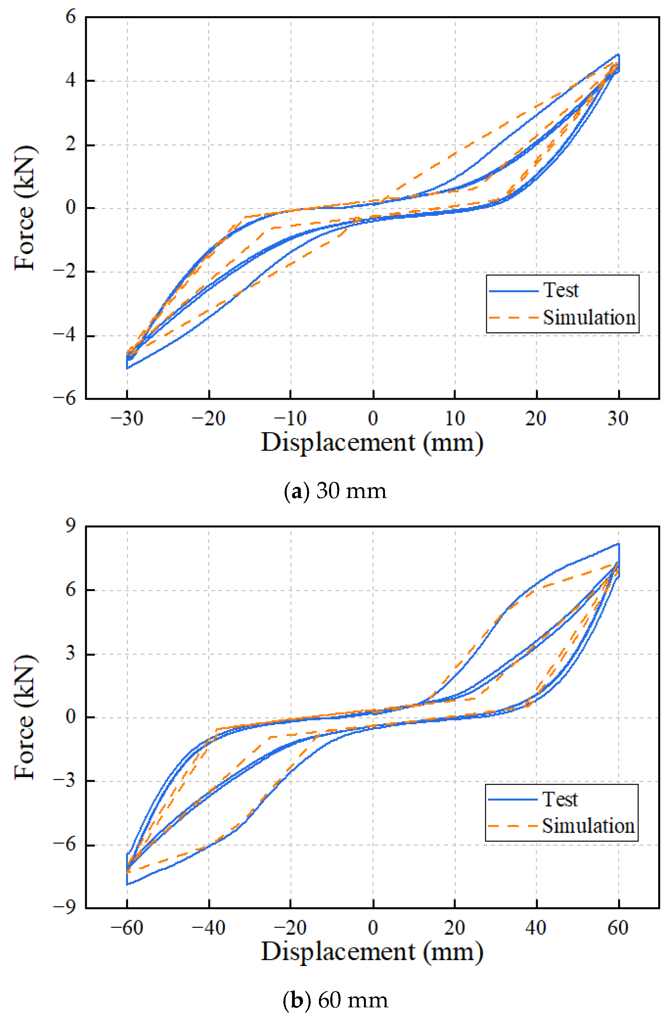
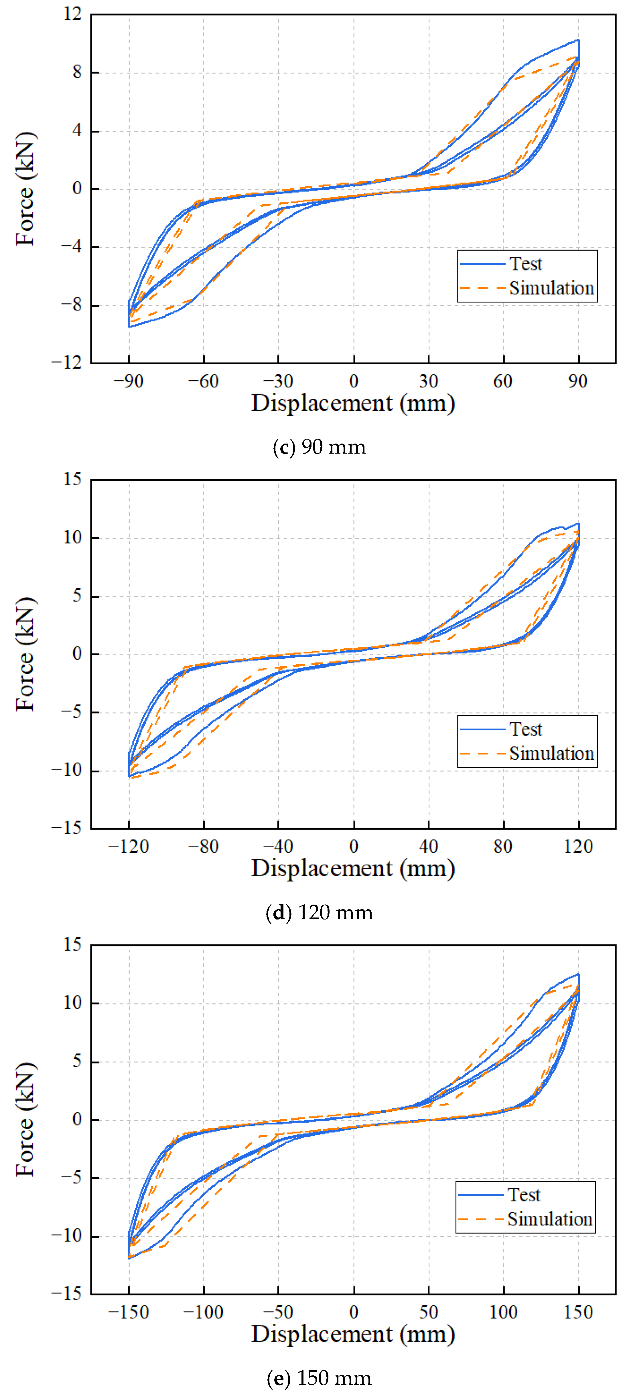
To more clearly demonstrate the difference between the simulation and test results, Figure 22 presents the comparison of the two hysteretic curves under five different loading amplitudes. It can be observed from the figure that the simplified analysis model can well simulate the mechanical behavior of the JM1R at different displacement amplitudes and accurately characterize the hysteretic behavior such as stiffness and strength degradation of the mortise-tenon joint during the loading process. However, there is a slight difference between the test results of the third loading cycle and those of the second loading cycle, which cannot be reflected by the simplified analysis model. This is because the simplified analysis model assumes that the damage degree of the mortise-tenon joint remains the same after the first and the second loading cycles; therefore, further loadings under the same amplitude no longer have an impact on the hysteretic performance.
Based on the proposed simplified simulation method above, the simulation of the JM2R model is also conducted, and the simulation results are presented in Figure 23 along with the test results. It can be seen from the comparison between the test and simulation results that both curves share almost the same varying trend. The key points of the two curves, such as the peak load values at different amplitudes and the onset of the reloading, are close, which indicates that the proposed simplified method can also capture the major mechanical characteristics of the mortise-tenon joint model with both the shear key and the NVED.
To quantitatively analyze the discrepancies between the simulation results and the test results, the stiffness and the equivalent damping ratios of the two models (namely JM1R and JM2R) under different loading amplitudes (namley 30 mm, 60 mm, 90 mm, 120 mm and 150 mm) and loading cycles (namely the first and the second loading cycles) are summarized in Table 4 and Table 5, with the corresponding relative errors also calculated and presented therein. The relative error is defined as the absolute value of the difference between the two sets of data divided by the test results.
In Table 4, the relative errors of the two models in all cases are smaller than 10%, which means the proposed simulation method can well reflect the varying properties of stiffness of the mortise-tenon joint model reinforced with the NVED.
In Table 5, the relative errors of the equivalent damping ratio are relatively larger than those of stiffness. However, it can be seen that with the increase in the loading amplitude, a declining trend is observed for the relative error. When the loading amplitude reaches 90 mm, the relative errors of the two models under different loading cycles are all smaller than 13%. This indicates that at small loading amplitudes, the energy dissipation of the model is correspondingly small, which leads to considerable errors in the equivalent damping ratio derived from the simplified model. However, the relative errors larger than 15% only occur in three cases, which all belong to the second loading cycle.

5. Conclusions

In this study, the NVED was used to enhance the seismic performance of the traditional mortise-tenon joint with consideration of the effect of the shear key. A mechanical test was firstly conducted on the NVED to reveal its hysteretic behavior and the dependence on both the loading amplitude and the loading frequency. The mortise-tenon joint specimens were then subjected to the cyclic loading tests to investigate the influence of the NVED. Based on the test results, a simplified simulation method was proposed to simulate the behaviors of both the joint and the NVED, and good simulation results were achieved. Some conclusions are drawn as follows.
(1) The shear key connecting the mortise of the column and the tenon of the beam can only slightly increase the load of the joint, and has little effect on the cyclic behavior derived from different loading cycles and various loading amplitudes.
(2) The installation of the NVED can significantly enhance the hysteretic performance of the mortise-tenon joint in both the first loading cycle and the subsequent cycles. The growth of the load and the dissipated energy can reach up to around 40% compared with the joint without the damper, especially at larger deformation.
(3) The Pinching4 material and the KikuchiAikenHDR material in OpenSees can respectively well simulate the hysteretic behaviors of the mortise-tenon joint and the NVED with their parameters calibrated by the test results.
(4) The proposed simplified simulation method, which uses zero-length elements to simulate the rotational behavior of the joint and the nonlinear behavior of the NVED, can fully account for the pinching effect and the degradation of the stiffness and the strength of the mortise-tenon joint model reinforced with the NVED.
Although the hysteretic behavior of the mortise-tenon joints and the reinforcing effect of the NVED have been experimentally and numerically investigated in this study, further research is needed. First, more tests of the mortise-tenon joints with and without the NVED will be conducted to investigate the long-term durability and environmental sensitivity of the dampers and the uncertainty in the measurements and the material properties. Second, based on the test results, the solid-element-based refined model, including the important nonlinear mechanisms, such as local contact behavior, timber crushing, bolt slip and geometric nonlinearity, could provide another way to numerically investigate the behavior of the joints. Finally, a series of shaking table tests on the whole jointed wooden structures will be conducted to reveal the influence of the NVED on the seismic responses of the structures, and the corresponding numerical model will be built and validated based on the proposed simplified simulation method.

Author Contributions

Conceptualization, B.S. and L.W.; methodology, B.S.; formal analysis, Y.W. and Z.H.; investigation, Y.W. and Z.H.; data curation, Y.W.; writing—original draft preparation, Y.W.; writing—review and editing, B.S.; supervision, B.S. and L.W.; project administration, B.S.; funding acquisition, B.S. All authors have read and agreed to the published version of the manuscript.

Funding

Financial support from the National Natural Science Foundation of China (No. 52408544) and the National Key R&D Program of China (No. 2023YFF0906304) is gratefully acknowledged.

Data Availability Statement

The original contributions presented in this study are included in the article. Further inquiries can be directed to the corresponding author.

Conflicts of Interest

The authors declare no conflicts of interest.

References

  1. Shi, X.; Sun, W.; Wang, W.; Li, T.; Chen, J.; Yu, P. Experimental study on the torsional hysteretic performance and seismic mechanism of traditional timber structures. Eng. Struct. 2026, 358, 122657. [Google Scholar] [CrossRef] [Scilit]
  2. Li, Y.; Deng, Y.; Li, A.; Jia, Y. Improving seismic performance for inclined historical building by using external protection structure: Case study of Yingxian wooden pagoda, China. J. Build. Eng. 2024, 96, 110381. [Google Scholar] [CrossRef] [Scilit]
  3. Deng, Y.; Li, Y.; Li, A. Seismic safety assessments of historical timber buildings using updated finite element models: Case study of Yingxian wooden pagoda, China. J. Build. Eng. 2023, 63, 105454. [Google Scholar] [CrossRef] [Scilit]
  4. Wang, J.; Chen, Z.; Cui, Z.; Wang, X. Experimental study on the lateral structural mechanical performance of Tang dynasty palace-style timber frame. Structures 2026, 86, 111285. [Google Scholar] [CrossRef] [Scilit]
  5. Yu, P.; Yang, Q.; Li, T.; Meng, X.; Zhou, M.; Shao, W. Spatial mechanical performance and load-resisting mechanism of the traditional Chinese wooden structure. Structures 2025, 82, 110689. [Google Scholar] [CrossRef] [Scilit]
  6. Sun, Z.; Xiang, P.; Jia, L.; Zhang, R. Seismic response and kinematic mechanisms of single-story pavilion-type timber frame based on shaking table test. Structures 2022, 45, 1701–1716. [Google Scholar] [CrossRef] [Scilit]
  7. Sha, B.; Xie, L.; Yong, X.; Li, A. An experimental study of the combined hysteretic behavior of dougong and upper frame in Yingxian Wood Pagoda. Constr. Build. Mater. 2021, 305, 124723. [Google Scholar] [CrossRef] [Scilit]
  8. Sha, B.; Xie, L.; Yong, X.; Li, A. Hysteretic behavior of an ancient Chinese multi-layer timber substructure: A full-scale experimental test and analytical model. J. Build. Eng. 2021, 43, 103163. [Google Scholar]
  9. Shi, K.; Dai, B.; Hu, D.; Luo, Z.; Zhang, F.; Tao, Z. Experimental study on seismic behavior of mortise-tenon joints of typical vernacular timber structures in southwest China. Structures 2026, 86, 111399. [Google Scholar] [CrossRef] [Scilit]
  10. Li, S.; Chen, L.; Jiang, L.; Li, J. Experimental Investigation on the Seismic Behavior of the Semi-Rigid One-Way Straight Mortise-Tenon Joint of a Historical Timber Building. Int. J. Archit. Herit. 2020, 14, 1135–1147. [Google Scholar]
  11. Liu, L.; Zhang, X.; Wu, Y. Lateral performance of traditional Chinese penetrated mortise-tenon frames: Experimental and numerical simulation. J. Build. Eng. 2025, 106, 112691. [Google Scholar] [CrossRef] [Scilit]
  12. Chun, Q.; Jin, H.; Dong, Y.; Hua, Y.; Han, Y. Research on Mechanical Properties of Dingtougong Mortise-Tenon Joints of Chinese Traditional Hall-Style Timber Buildings Built in the Song and Yuan Dynasties. Int. J. Archit. Herit. 2020, 14, 729–750. [Google Scholar] [CrossRef] [Scilit]
  13. Wu, Y.; Lin, H.; Wang, L.; Xie, Q.; Zhang, L. Lateral performance of mortise-tenon jointed frames in multi-story traditional heavy timber structures: Mechanism and quantification. Eng. Struct. 2023, 288, 116218. [Google Scholar] [CrossRef] [Scilit]
  14. Zhang, B.; Xie, Q.; Li, S.; Zhang, L.; Wu, Y. Effects of gaps on the rotational performance of traditional straight mortise-tenon joints. Eng. Struct. 2022, 260, 114231. [Google Scholar] [CrossRef] [Scilit]
  15. Ma, L.; Xue, J.; Zhang, X. Seismic Performance Evaluation of Damaged Ancient Timber Structures with Looseness Mortise-Tenon Joints. Int. J. Archit. Herit. 2023, 17, 2054–2068. [Google Scholar] [CrossRef] [Scilit]
  16. Keita, O.; Yasutoshi, S.; Mariko, Y. Theoretical estimation of the mechanical performance of traditional mortise-tenon joint involving a gap. J. Wood Sci. 2016, 62, 242–250. [Google Scholar]
  17. Zhang, B.; Xie, Q.; Hu, J.; Zhang, L.; Wu, Y. Rotational Performance of Traditional Straight Mortise-Tenon Joints with Gap: Theoretical Model and Numerical Analyses. Int. J. Archit. Herit. 2023, 17, 1701–1718. [Google Scholar] [CrossRef] [Scilit]
  18. Yu, P.; Yang, Q.; Law, S.-S. Lateral performances of traditional wooden frame with loose penetrated mortise-tenon connection and column foot models. J. Build. Eng. 2022, 47, 103793. [Google Scholar] [CrossRef] [Scilit]
  19. Crayssac, E.; Song, X.; Wu, Y.; Li, K. Lateral performance of mortise-tenon jointed traditional timber frames with wood panel infill. Eng. Struct. 2018, 161, 223–230. [Google Scholar] [CrossRef] [Scilit]
  20. Lydia, P.; Nikiforos, M.; Charalampos, M. Shaking table tests on single-bay timber-framed wall specimens with fired brick and adobe block infills and mortise-tenon joints. J. Build. Eng. 2023, 76, 107380. [Google Scholar]
  21. Song, X.; Lu, Y.; Zhang, B.; Chen, X. Seismic behavior of damaged Li-Tie style timber frames with brick masonry infills: Experimental test, finite element analyses, and behavior degradation. J. Build. Eng. 2024, 86, 108848. [Google Scholar] [CrossRef] [Scilit]
  22. He, J.; Li, M.; Xie, L.; Bai, X. Theoretical model of the restoring bending moment of wooden wedge-reinforced penetrated mortise-tenon joints in traditional timber structure. J. Build. Eng. 2026, 120, 115582. [Google Scholar] [CrossRef] [Scilit]
  23. Yu, P.; Li, T.; Yang, Q. Inelastic behavior of mortise-tenon jointed traditional timber frame with free-standing columns. Int. J. Archit. Herit. 2024, 18, 1059–1076. [Google Scholar] [CrossRef] [Scilit]
  24. Yu, P.; Yang, Q.; Li, T.; Meng, X.; Shi, X.; Chen, J. Quantitative contribution assessment of joints and components to the load-carrying capacity of ancient timber frame. Structures 2024, 59, 105739. [Google Scholar] [CrossRef] [Scilit]
  25. Li, Z.; Kitamori, A.; Zhang, X.; Wu, Y.; Zhang, L.; Xue, J. Analytical investigation on the rotational behavior of dovetail mortise-tenon joints between beams and columns in traditional Chinese timber frames. J. Wood Sci. 2024, 70, 50. [Google Scholar] [CrossRef] [Scilit]
  26. Yu, P.; Li, T.; Yang, Q.; Shi, X.; Meng, X.; Chen, J. Numerical modelling strategy and load resisting mechanism of palace-type traditional wooden frame. Eng. Struct. 2024, 319, 118851. [Google Scholar] [CrossRef] [Scilit]
  27. Zhang, B.; Xie, Q.; Li, S.; Zhang, L.; Xue, J. Numerical analysis of traditional Chinese timber structure: Simplified finite element model and composite elements of joints. J. Build. Eng. 2023, 67, 106027. [Google Scholar] [CrossRef] [Scilit]
  28. Wu, Y.; Song, X.; Ventura, C.; Lam, F. Modeling hysteretic behavior of lateral load-resisting elements in traditional Chinese timber structures. J. Struct. Eng. 2020, 146, 04020062. [Google Scholar] [CrossRef] [Scilit]
  29. Zhou, R.; Xue, J.; Ye, C.; Song, D.; Wu, C. Restoring force models of key joints in ancient timber structures considering plastic deformation damage. Structures 2025, 82, 110550. [Google Scholar] [CrossRef] [Scilit]
  30. Zhang, X.; Liu, K.; Cui, L.; Liu, L. Prediction of the Moment-Rotation Relationship of Dovetail Mortise-Tenon Joint Based on Support Vector Regression. Int. J. Archit. Herit. 2025, 19, 2608–2621. [Google Scholar] [CrossRef] [Scilit]
  31. Yang, W.; Gao, Y.; Su, H.; Tao, Z.; Lai, Z.; Su, H. Seismic performance of timber dovetail mortise-tenon joints with different lateral tightness: Experimental tests and hysteresis model parameter identification. Structures 2025, 82, 110389. [Google Scholar] [CrossRef] [Scilit]
  32. He, J.; Liu, K.; Xie, L.; Wang, X.; Yang, W.; Zhao, W. Experimental and numerical studies on influences of wedge reinforcement on seismic performance of loose penetrated mortise-tenon joints. J. Build. Eng. 2024, 91, 109610. [Google Scholar] [CrossRef] [Scilit]
  33. Dong, H.; Liang, X.; Cao, W.; Jin, Y. Seismic behavior of mortise–tenon joints reinforced with lightweight steel components. J. Build. Eng. 2023, 65, 105755. [Google Scholar] [CrossRef] [Scilit]
  34. Shen, S.; Sun, Y.; Wang, Y.; Qi, Y.; Jiang, S.; Fu, X.; Wang, M. Damaged mortise-tenon joint strengthened using an assembled spring-steel hoop based on a design of similar rotational stiffness. J. Build. Eng. 2024, 95, 110101. [Google Scholar] [CrossRef] [Scilit]
  35. Guo, T.; Yang, N.; Zhou, H.; Wang, S. Experimental and Numerical Studies on the Traditional Penetration Mortise-Tenon Connection Reinforced by Self-Tapping Screws. Forests 2022, 13, 513. [Google Scholar] [CrossRef] [Scilit]
  36. Yin, T.; Guo, C.; Wang, Z.; Zheng, W.; Gong, M. Mechanical properties of mortise-tenon joints reinforced by self-tapping screws with different insertion methods. Constr. Build. Mater. 2023, 366, 130243. [Google Scholar] [CrossRef] [Scilit]
  37. Xue, J.; Wu, C.; Zhang, X.; Zhang, Y. Effect of pre-tension in superelastic shape memory alloy on cyclic behavior of reinforced mortise-tenon joints. Constr. Build. Mater. 2020, 241, 118136. [Google Scholar] [CrossRef] [Scilit]
  38. Xie, Q.; Zhang, L.; Zhou, W.; Wang, L.; Zhou, T. Cyclical behavior of timber mortise-tenon joints strengthened with shape memory alloy: Experiments and moment-rotation model. Int. J. Archit. Herit. 2019, 13, 1209–1222. [Google Scholar] [CrossRef] [Scilit]
  39. Chang, P.; Zhao, R.; Feng, Q.; Yang, N. Theoretical derivation and experimental validation of a restoring force model for a self-centering rotational friction damper with variable friction device. Structures 2025, 78, 109267. [Google Scholar] [CrossRef] [Scilit]
  40. Xue, J.; Wu, C.; Zhang, X.; Qi, Z. Experimental and numerical study of mortise-tenon joints reinforced with innovative friction damper. Eng. Struct. 2021, 230, 111701. [Google Scholar] [CrossRef] [Scilit]
  41. Dai, B.; Gao, Y.; Tao, Z.; Su, H.; Su, H. Fan-shaped Shear Dampers Strengthen Mortise-tenon Joints in Chinese Traditional Timber Structures. Int. J. Archit. Herit. 2023, 17, 1079–1092. [Google Scholar] [CrossRef] [Scilit]
  42. Xu, J.; Sun, D.; Liu, E.; Guo, T.; Li, A. Optimal design of right-angle viscoelastic dampers for seismic performance of ancient timber structure via improved multi-objective particle swarm algorithm. Structures 2025, 77, 109123. [Google Scholar] [CrossRef] [Scilit]
  43. Yu, S.; Pan, W.; Su, H.; Ye, L. Experiment and theoretical study on mortise-tenon joints reinforced by support-type viscoelastic damper. J. Build. Eng. 2024, 87, 109049. [Google Scholar] [CrossRef] [Scilit]
  44. Yi, D.; Fan, Y.; Pan, Y. Hysteretic Behavior Characterization of Mortise and Tenon Joints Reinforced Using Viscoelastic Dampers in Historic Timber Frames. J. Struct. Eng. 2025, 151, 04025024. [Google Scholar] [CrossRef] [Scilit]
  45. Mikayilov, E.; Santeramo, M.; De Carolis, S.; Carbone, G.; Putignano, C. Micro-oscillating indentation of viscoelastic solids: A combined numerical, analytical and experimental investigation. Int. J. Solids Struct. 2025, 322, 113582. [Google Scholar] [CrossRef] [Scilit]
  46. Nasab, M.S.E.; Guo, Y.; Kim, J. Seismic retrofit of a soft first-story building using viscoelastic dampers considering inherent uncertainties. J. Build. Eng. 2022, 47, 103866. [Google Scholar] [CrossRef] [Scilit]
  47. Su, Y.; Wang, F.; Zong, S.; Liu, Y. Experimental study on the damping properties of NBR-based viscoelastic materials enhanced by minimal particles. J. Rubber Res. 2021, 24, 735–744. [Google Scholar] [CrossRef] [Scilit]
  48. Zhang, H.; Su, Y.; Li, A.; Guo, P. Experimental investigation of novel pre-compressed viscoelastic dampers with different matrix materials. Structures 2023, 53, 625–641. [Google Scholar] [CrossRef] [Scilit]
  49. Li, J. Yingzaofashi; People’s Publishing House: Beijing, China, 2011. (In Chinese) [Google Scholar]
  50. JG/T 209-2012; Dampers for Vibration Energy Dissipation of Buildings. Ministry of Housing and Urban-Rural Development of the People’s Republic of China: Beijing, China, 2012. (In Chinese)
  51. ISO-16670; Timber Structures: Joints Made with Mechanical Fasteners: QusaiStatic Reversed-Cyclic Test Method. International Organization for Standardization: Geneva, Switzerland, 2003.
  52. Nerilli, F.; Ahmadi, H.M.; Imperatore, S.; Vairo, G. Bond–slip performance of GFRP rebars in concrete under alkaline and thermal conditioning. J. Compos. Sci. 2026, 10, 131. [Google Scholar] [CrossRef] [Scilit]
  53. He, J.; Yu, P.; Wang, J.; Yang, Q.; Han, M.; Xie, L. Theoretical model of bending moment for the penetrated mortise-tenon joint involving gaps in traditional timber structure. J. Build. Eng. 2021, 42, 103102. [Google Scholar] [CrossRef] [Scilit]
Figure 1. Representative historic ancient wooden structures. (a) Main Hall of the Nanchan Temple. (b) Yingxian Wooden Pagoda.
Buildings 16 02183 g001
Figure 2. Configuration of two mortise-tenon joint models. (a) Joint model (JM1). (b) Joint model with a shear key (JM2).
Buildings 16 02183 g002
Figure 3. Dimension of the model. (unit: mm).
Buildings 16 02183 g003
Figure 4. Mechanical test of the wood. (a) Perpendicular to grain direction. (b) Along grain direction.
Buildings 16 02183 g004
Figure 5. Configuration and test of the NVED. (unit: mm).
Buildings 16 02183 g005
Figure 6. Hysteretic behavior of the NVED at various loading amplitudes.
Buildings 16 02183 g006
Figure 7. Hysteretic behavior of the NVED at various loading frequencies.
Buildings 16 02183 g007
Figure 8. Setup of the specimens.
Buildings 16 02183 g008
Figure 9. Loading protocol.
Buildings 16 02183 g009
Figure 10. Hysteretic curves of JM1 and JM2.
Buildings 16 02183 g010
Figure 11. Hysteretic curves of JM1 and JM1R.
Buildings 16 02183 g011
Figure 12. Hysteretic curves of JM2 and JM2R.
Buildings 16 02183 g012
Figure 13. Skeleton curves of the four models. (a) First loading cycle of each displacement amplitude. (b) Second loading cycle of each displacement amplitude.
Buildings 16 02183 g013
Figure 14. Stiffness of the four models.
Buildings 16 02183 g014
Figure 15. Dissipated energy of the four models.
Buildings 16 02183 g015
Figure 16. Equivalent damping ratio of the four models.
Buildings 16 02183 g016
Figure 17. Simplified model of the JM1. (* denotes the key point in the hysteretic rule).
Buildings 16 02183 g017
Figure 18. Simulation results of the JM1 model.
Buildings 16 02183 g018
Figure 19. Simulation results of the NVED.
Buildings 16 02183 g019
Figure 20. Simplified model of the JM1R.
Buildings 16 02183 g020
Figure 21. Simulation results of the JM1R.
Buildings 16 02183 g021
Figure 22. Simulation results of JM1R at various loading amplitudes.
Buildings 16 02183 g022aBuildings 16 02183 g022b
Figure 23. Simulation results of the JM2R.
Buildings 16 02183 g023
Table 1. Mechanical properties of the wood.
MC/%D/(g/cm3)CL/MPaCR/MPaCT/MPaEL/MPaER/MPaET/MPa
11.40.6570.36.113.62981507475
Note: MC-moisture content; D-density; C-compressive strength; E-elastic modulus; L-longitudinal direction (grain direction); R-radial direction; T-tangential direction.
Table 2. Maximum damping force of the NVED at various loading amplitudes.
Loading displacement (mm)51015203040
Maximum damping force (kN)1.141.842.402.944.216.21
Table 3. Maximum damping force of the NVED at various loading frequencies.
Loading rate (Hz)0.010.10.20.51.0
Maximum force (kN)2.943.053.474.094.68
Table 4. Comparison of the stiffness between the test and the simulation.
AmplitudeFirst Loading CycleSecond Loading Cycle
306090120150306090120150
JM1R
model
Test (kN/m)164.6134.0109.890.781.5152.9119.897.981.573.8
Simulation (kN/m)155.3121.7102.088.578.4151.3116.297.883.674.4
Relative error(%)5.79.27.22.43.81.03.00.12.60.8
JM2R
model
Test (kN/m)148.3134.6116.5100.791.4141.4122.3105.191.183.4
Simulation (kN/m)153.0129.4111.4100.092.0149.0123.8107.195.288.0
Relative error (%)3.23.94.40.70.65.41.31.84.55.5
Table 5. Comparison of the equivalent damping ratio between the test and the simulation.
AmplitudeFirst Loading CycleSecond Loading Cycle
306090120150306090120150
JM1R
model
Test0.0830.1220.1120.1060.0980.0510.0640.0710.0760.076
Simulation0.0880.1080.0980.0990.0970.0410.0540.0620.0690.073
Relative error (%)6.411.612.46.71.220.315.812.59.64.1
JM2R
model
Test0.0670.1050.0980.0930.0870.0390.0510.0570.0630.065
Simulation0.0770.1010.0950.0920.0890.0470.0540.0600.0640.067
Relative error (%)14.63.43.61.52.418.84.94.62.03.3
Disclaimer/Publisher’s Note: The statements, opinions and data contained in all publications are solely those of the individual author(s) and contributor(s) and not of MDPI and/or the editor(s). MDPI and/or the editor(s) disclaim responsibility for any injury to people or property resulting from any ideas, methods, instructions or products referred to in the content.