Abstract
Based on the Guangzhou Business Center project, a typical super high-rise building with an asymmetric plan, taking the construction speed, closure time of mega braces and belt trusses as influencing factors, a parametric analysis on its lateral and vertical deformations, as well as the maximum stress of key structural members was conducted. The analysis results indicated that the construction speed had a relatively small impact on the deformation and the maximum stress of key members. However, synchronous closure of belt truss compared with the delayed closure would result in smaller horizontal and vertical deformation differences, as well as the stress of belt truss. Meanwhile, the closure timing of the mega braces had little influence on the vertical deformation difference and the stress of belt truss. And the earlier the closure, the smaller the horizontal drift ratio, the greater the maximum stress of the mega braces. Further, deformation control measurements were brought forward. On the one hand, FEM simulation was carried out according to the above construction suggestions. On the other hand, real-time monitoring was also used. Finally, by comparing both results, proposed construction deformation control measures and simulation methods were verified.
1. Introduction
Existing studies indicated that the horizontal and vertical deformation differences during the construction of super high-rise steel structures not only affect construction quality but also generate additional stresses in structural components from a design perspective, particularly vertical deformation differences [1,2,3,4,5]. These differences would cause forced support displacements between adjacent components, resulting in additional bending moments and shear forces. Without appropriate measures to reduce these deformation differences, additional stresses may reach significant levels, causing components to yield or even suffer cracking [6,7]. Thus, deformation differences during the construction period should be considered for super high-rise buildings, especially for those with an asymmetric plan.
Practical applications have shown that these deformations and differences could be studied and predicted accurately by FEM parametric analysis, construction simulation, and real-time monitoring [8,9,10,11,12]. Firstly, a parametric study could reveal the deformation characteristics and its influencing factors. Then, deformation control measures would be proposed. Further, through construction simulation and real-time monitoring at each stage, proposed deformation control measures and the construction model could be verified, which in turn could effectively control the horizontal and vertical deformations of the super high-rise buildings during construction.
Brownjohn et al. used the above method in a 280 m-high, 65-story office building in Singapore and identified the key factors affecting simulation accuracy by comparing the simulation results with the monitoring data [13,14]. J.R. Wu et al. conducted construction simulations of a super high-rise building using ETABS, considering the effects of overall loading, concrete shrinkage, and creep on vertical and horizontal displacements. Gao et al. monitored and simulated the construction of a 335 m-high building, indicating that the construction speed would significantly influence the vertical deformation [15].
However, the above studies mainly focused on structures with a symmetric plan. Super high-rise structures with an asymmetric plan would differ significantly due to the dislocation of the center of gravity and rigidity, leading to different structural behavior [16,17,18,19].
The design of current projects, those structures with an asymmetric plan, still largely rely on engineers’ experience, while summarizations are still needed in order to form the corresponding design theory or method. Further, in terms of cost considerations, most super high-rise buildings would adopt steel–concrete hybrid structures rather than pure steel structures, not to mention those with an asymmetric plan [20,21,22,23,24].
Therefore, this article parametrically studied the influence of construction speed, the closure timing of mega braces and belt truss on the horizontal and vertical deformations, as well as the stress of key structural components during the construction period based on the asymmetric super high-rise steel structure project—Guangzhou Business Center. The deformation control measures were then proposed based on the analysis and verified by comparing the construction simulation and real-time monitoring results, in order to provide case support and technical guidance for asymmetric super high-rise steel structures in terms of deformation control during construction.
2. Project Overview
The Guangzhou Business Center project was located at Guangzhou’s Pazhou West District, with a height of 375.5 m, 60 floors above ground, 5 underground, and a total construction area of 207,011 m2. It adopted a steel mega frame (concrete-filled steel tube columns) + steel braces + eccentric steel braced frame. The steel structure had consumed approximately 49,820 tons of steel. And two belt trusses were designed, which located on the 4F–7F and 34F–35F, as shown in Figure 1.
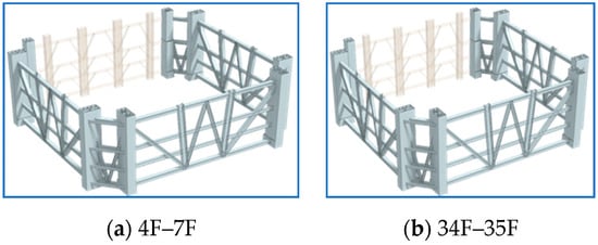
Figure 1.
The belt trusses.
Mega braces were distributed on the south, north, and east facades of the tower, with double-web box sections. The maximum plate thickness was 80 mm. And the maximum section was 1500 × 1200 × 80 (Q390GJC). The overall structure featured an asymmetric plan with a mega frame-structure (concrete-filled steel tube) east side, and an eccentric-braced-frame west side, resulting in a north–south symmetric and east–west asymmetric plan, as shown in Figure 2.
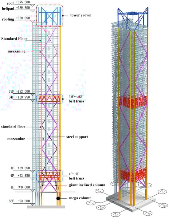
Figure 2.
Structure diagram of Guangzhou Business Center (Asymmetric Plan).
3. Factors Influencing Deformation during Construction
3.1. Factors Influencing Horizontal Deformation
For super high-rise steel structures, the factors influencing the horizontal deformation during construction would include
- (1)
- Dead Load: As the structure installation progresses, the building’s gravity center will bear greater asymmetric or uneven loads, affecting its verticality and increasing the horizontal deformation.
- (2)
- Horizontal Load: With increasing building height during construction, horizontal loads, especially wind loads, will also increase, causing greater horizontal deformation.
- (3)
- Shrinkage and Creep of Concrete: Long-term shrinkage and creep effects in concrete will cause increasing asymmetricity between stiffness and gravity centers, which will influence the horizontal deformation.
- (4)
- Construction Speed: Related to concrete shrinkage and creep, it will also affect the development of horizontal deformation.
- (5)
- Closure Timing of Mega Braces and Belt Truss: Closure of mega braces and belt truss will influence the overall stiffness of structure during construction.
3.2. Factors Influencing Vertical Deformation
Over 85% of vertical loads in super high-rise buildings come from self-weight. The construction period’s long duration and varying loads make vertical load calculations even more complicated. As construction progresses, the weight continuously adds to the structure, which is different from one-time load application. And structural stiffness also changes with the construction process.
On the other hand, concrete-filled steel tube structures will experience different shrinkage and creep effect compared to that of reinforced concrete structures, causing significant deformation differences between steel tube columns. Extended construction periods accumulate creep effects, leading to more notable deformations than ordinary buildings.
Further, the construction speed, closure timing of mega braces and belt truss will also make a difference on the vertical deformation.
4. Numerical Modelling
4.1. Assumptions and Settings
- (1)
- Concrete time-varying model assumptions
Concrete-filled steel tube columns were analyzed using “construction stage combined sections”, as shown in Figure 3, in which the concrete shrinkage and creep effect should be considered.
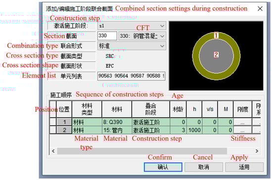
Figure 3.
Setting about combined intersection of CFT in Midas/GEN.
There was obviously a difference between ordinary concrete exposed to the atmosphere and concrete in the steel tube. In the steel tube, the concrete was encased and placed in a high-humidity environment. The average humidity of the concrete would not be lower than 90%. Therefore, according to the existing research, the CEB-FIP model could be used to simulate the shrinkage and creep effect. And the theoretical thickness of concrete components should be defined as infinity. Further, ordinary Portland cement Bsc was set at 5.0, with shrinkage starting from the third day. Above all, parameter settings for C80 concrete in steel tubes are shown in Figure 4.
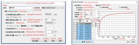
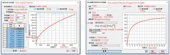
Figure 4.
Settings for the strength increase in C80 in CFT in Midas/GEN.
- (2)
- Structural group divisions
The whole structure was divided into 55 groups along the height according to the minimum construction unit, as shown in Table 1.

Table 1.
Structural group divisions.
- (3)
- Key indicators and floor division
Vertical displacement was measured at the top of mega columns, with eight external and four internal mega columns selected, as shown in Figure 5.
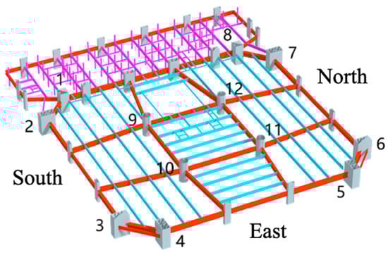
Figure 5.
Numbers of mega columns.
Vertical displacement differences (VDD) were calculated by Equations (1)–(4).
VDD#1: (1 mega column + 2 mega column)/2–9 mega column
VDD#2: (3 mega column + 4 mega column)/2–10 mega column
VDD#3: (5 mega column + 6 mega column)/2–11 mega column
VDD#4: (7 mega column + 8 mega column)/2–12 mega column
Meanwhile, the whole structure was divided into seven sections along the height based on the positions of mega braces, as shown in Figure 6. Defined vertical displacement (difference) values are calculated for the top of columns in these sections.
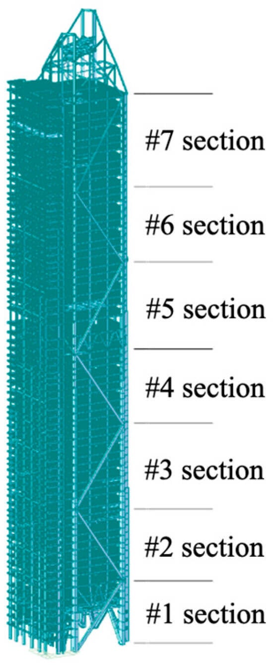
Figure 6.
Sections of the structure.
4.2. Key FEM Definitions
- loads and load combinations
To ensure construction safety and quality, structural strength, stiffness, and stability were verified at each construction stage, with temporary measures if necessary.
- (1)
- Dead Loads
- Self-Weight: Concrete and steel densities are 2500 kg/m3 and 7850 kg/m3, respectively. The software calculates self-weight based on material density and component geometry.
- Additional Dead Load: Partitions and curtain walls are applied as uniformly distributed loads on floor surfaces.
- (2)
- Live Loads
- Construction Live Load: 2.0 kN/m2, applied as uniformly distributed loads on floor surfaces, acting on the floor below the construction level.
- Wind Load: 10-year return period (basic wind pressure 0.30 kPa), considered along ±X and ±Y directions for structural force impact, not for deformation.
- (3)
- Load Combinations
- Strength Check: 1.3 × Dead Load + Live Load + Wind Load
- Deformation Calculation: 1.0 × Dead Load
- 2.
- Element types and boundary conditions
All the columns and beams were modelled as beam-type element with six degrees of freedom and shear deformation considered in default. Both ends of columns and beams were defined as fixed ends. The slabs were modelled as plate element with six degrees of freedom and three kinds of flexural stiffness with respect to the main directions. Out-of-plane flexural stiffness were considered for the slab. Meanwhile, the ordinary braces were defined as truss elements, with both ends pinned.
As for the boundary conditions, the bottom end of columns and braces in the first floor was defined as fixed end. Except for above boundary condition, there was no other particular boundary condition defined for the finite element model.
- 3.
- Material definitions
Since all the structural members should be designed as elastic during the construction period, the steel material was thus defined as elastic. Poisson’s ratio of steel was defined as 0.3 and the modulus of elasticity was 2.06 × 10⁵ MPa.
4.3. Construction Speed
The complexity of construction site conditions and material supply would affect the construction speed, which in turn would cause a big difference in the concrete shrinkage and creep. This section simulated different construction speeds from Table 2 to analyze their influence on the structural deformation.
Table 2.
Different construction speed plans.
4.4. The Closure Timing of Belt Trusses and Mega Braces
- (1)
- Synchronous closure with the frame,
- (2)
- 1 section lagging behind,
- (3)
- 2 sections lagging behind.
5. Parametric Analysis Results
5.1. Influence of Construction Speed
- (1)
- On lateral displacement
According to the construction speed listed in Table 2, numerical simulation of the influence of construction speed on the lateral displacement considering concrete shrinkage and creep effects was conducted.
The analysis results showed that in the X direction (the axis of symmetry), the maximum story displacement decreased as the construction speed increased, especially for the floors above the 40th, where the max story displacement in the case of 3 d/floor was approximately 1.5 fold that in the case of 12 d/floor. In the Y direction (the asymmetric axis), the construction speed exhibited little impact, as shown in Figure 7.
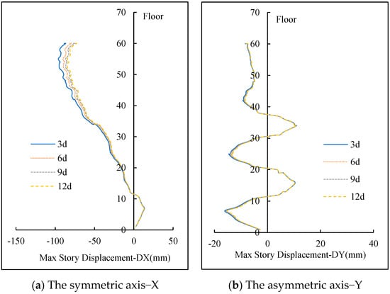
Figure 7.
Max story displacement.
From the view of the structural indicator in terms of story drift, the construction speed had a minor effect in both directions, as shown in Figure 8.
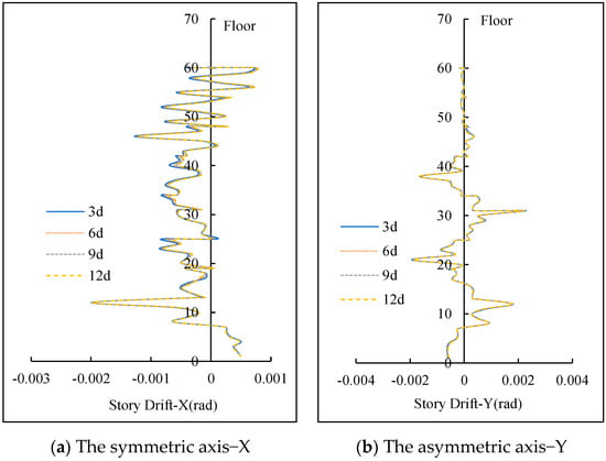
Figure 8.
Story drift.
- (2)
- On vertical displacement difference (VDD)
The analysis results indicated that the vertical displacement of the internal mega columns was significantly greater than that of the external mega columns. For instance, the vertical displacement of typical internal mega column #10 on the southeast side is approximately 0.93 m, while the maximum vertical displacement of typical external column #4 was only 0.40 m, as shown in Figure 9.
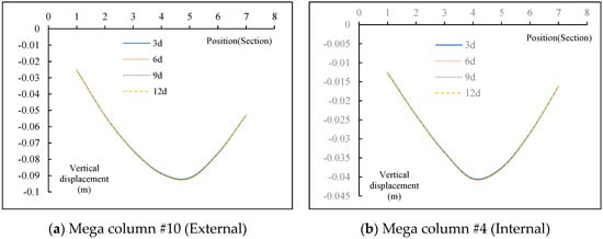
Figure 9.
Influence of construction speed on vertical displacement of mega column.
Then, according to Equations (1)–(4), the vertical displacement differences could be obtained, which were varied on each side. The vertical displacement difference of the mega columns near the east side was slightly larger than that on the west side. The vertical displacement difference in #5 section was the largest. However, the construction speed had almost no influence on the VDD between external and internal mega columns, as shown in Figure 10.
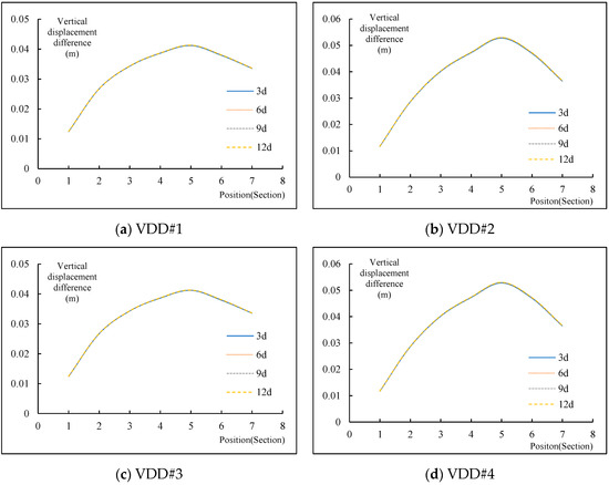
Figure 10.
Influence of construction speed on VDD of mega column.
- (3)
- On max stress of key components
The analysis results also indicated that the construction speed had nothing to do with the stress of mega braces, as shown in Figure 11.
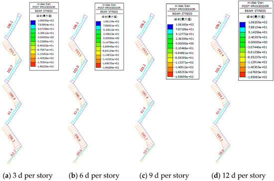
Figure 11.
Influence of construction speed on the stress of mega braces.
Meanwhile, the max stresses of belt truss were almost the same when the construction speed increased, as shown in Table 3.
Table 3.
The maximum stress of belt truss under different construction speeds.
5.2. Influence of the Closure Timing of Belt Truss
- (1)
- On lateral displacement
According to the parameters determined in Section 4.4, the results showed that the closure timing of belt trusses had no significant influence on the lateral displacement in the symmetric direction (X direction). However, for lateral displacement in the asymmetric direction (near the west side), within the range of the 35th–50th floors, the earlier the belt trusses were closed, the smaller the max story displacement, as shown in Figure 12. The deformation when it was closed with two sections lagging behind was approximately 1.2 fold that of synchronous closure.
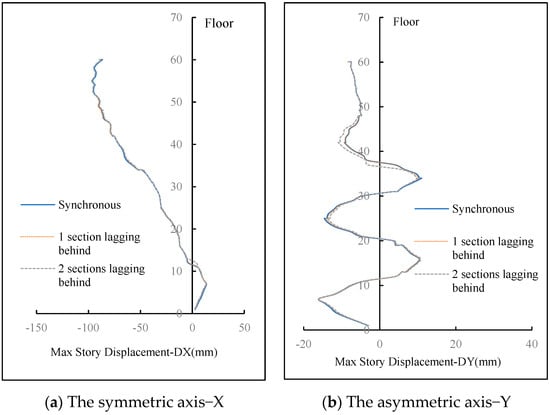
Figure 12.
Max story displacement.
However, again, its impact on the drift story is minor, as shown in Figure 13.
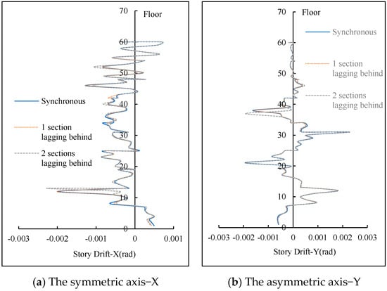
Figure 13.
Story drift.
- (2)
- On vertical displacement difference
On the other hand, the closure timing of belt trusses had a more noticeable impact on the vertical displacement difference (VDD). The earlier the belt trusses were closed, the smaller the VDD, especially within #3–#5 sections. The VDD with two sections lagging behind was approximately 1.15 fold that under synchronous closure, as shown in Figure 14.
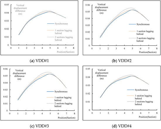
Figure 14.
Influence of the closure timing of belt trusses on VDD.
- (3)
- On max stress of key components
The stress contour of the mega braces indicated almost no change with different belt truss closure timings, as shown in Figure 15. However, the earlier the trusses were closed, the smaller the stress. In the case of two sections lagging behind, the maximum stress of belt truss was approximately 1.7 fold that with synchronous closure, as shown in Table 4, which had also exceeded the ultimate strength of the steel material (Q460D). It was obviously not conservatively safe. Therefore, it was recommended that the belt trusses should be closed synchronously.
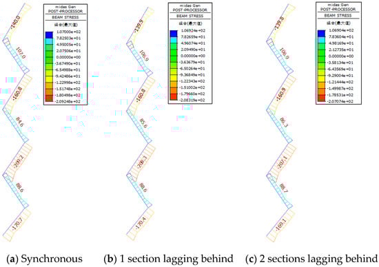
Figure 15.
Influence of the closure timing of belt trusses on the stress of mega braces.
Table 4.
The maximum stress of belt truss under different closure timings.
5.3. Influence of the Closure Timing of Mega Braces
- (1)
- On lateral displacement
Similar to the parametric analysis of belt trusses, the analysis results indicated that the closure timing of mega braces had minimal impact on the lateral displacement in the direction of the symmetric axis. However, it significantly affected the lateral displacement with respect to the direction of the asymmetric axis. The earlier the braces were closed, the greater the lateral displacement. The max story displacement of the two sections lagging behind case was only 0.65 fold that with synchronous closure, as shown in Figure 16. The story drift comparisons were drawn in Figure 17, which also indicated that the max story drift of former case was approximately 0.80 fold that with synchronous closure. The reason for which the lateral displacement when the mega braces were synchronously closed was larger than that when mega braces were closed with two sections lagging behind was the asymmetric plan of structure. During the construction period, the lateral displacement of the structure was mainly determined by the vertical loads rather than the lateral loads, such as the wind force. The wind load was insignificantly small then. In this project, the synchronous closure of the mega braces had made the structure more asymmetric than the later-closure case, which made the lateral displacement under the vertical loads even larger.
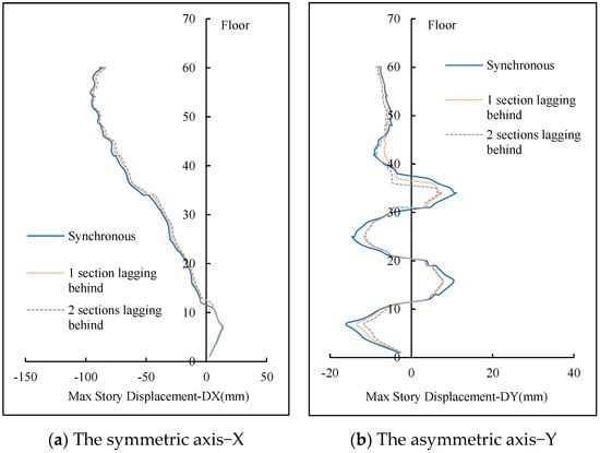
Figure 16.
Max story displacement.
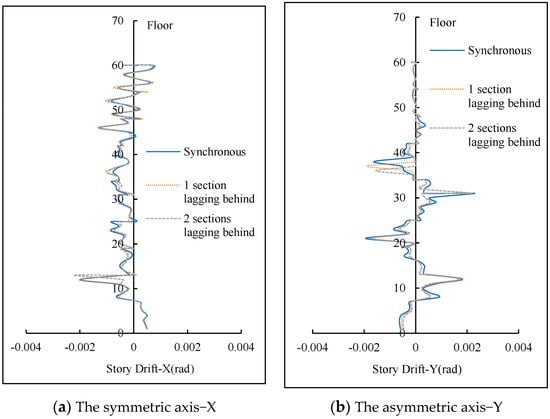
Figure 17.
Story drift.
- (2)
- On vertical displacement difference
The closure timing of mega braces had a less impact on the vertical displacement difference (VDD) of mega columns, as shown in Figure 18. Curves of all cases are almost overlapping.
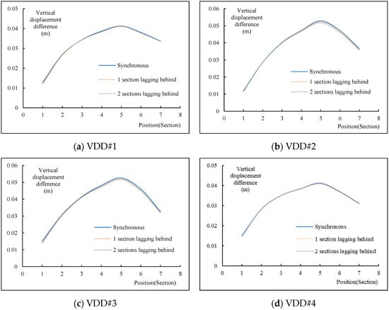
Figure 18.
Influence of the closure timing of mega braces on VDD.
- (3)
- On max stress of key components
Unlike the belt trusses, different closure timings of mega braces had the minimal impact on the stress of the belt trusses, as shown in Table 5.
Table 5.
The maximum stress of belt truss under different closure timings.
Similarly, the later the braces were closed, the smaller the stress of mega braces, as shown in Figure 19. Therefore, it was recommended that the mega braces could be closed with two sections lagging behind.
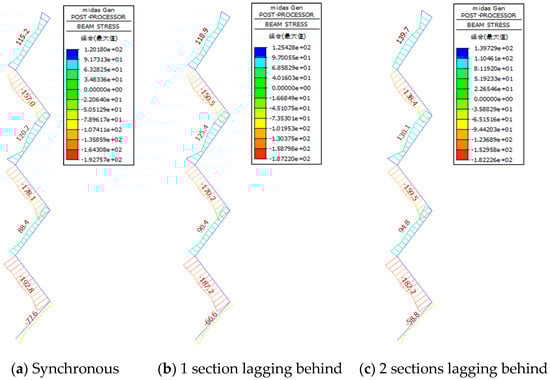
Figure 19.
Influence of the closure timing of mega braces on its stress.
6. Suggestions for Deformation Control
6.1. Construction Speed Suggestion
The parametric analysis results indicated that construction speed had a minimal impact on the horizontal and vertical deformation of super high-rise steel structures as well as the stress of key components. Therefore, the construction speed should be determined comprehensively by considering the factors such as project schedule, manpower, material resources, natural conditions, and costs. Therefore, in this paper, it was recommended that the construction speed would better be 6 days per floor.
6.2. The Closure Timing of Belt Trusses Suggestion
The parametric analysis results also indicated that when the belt trusses were closed synchronously, the lateral displacement and the vertical differences were relatively smaller, compared to the cases of one section and two sections lagging behind. And the maximum stresses of belt trusses were also the lowest. On the other hand, the closure timing had almost no impact on the stress of the mega braces. Therefore, it was recommended that the belt trusses would better be closed synchronously.
6.3. The Closure Timing of Mega Braces Suggestion
It can be seen from the analysis that the closure timing of mega braces had a minimal impact on the vertical displacement difference and the maximum stress of belt trusses. However, the later the braces were closed, the smaller the stress of mega braces, as well as the smaller story drift in the asymmetric axis direction. Therefore, it was recommended that the mega braces could be closed with two sections lagging behind.
7. Numerical Simulation-Practical Project
Based on the construction deformation control measures suggested by Section 6 and considering the actual situation of Guangzhou Business Center project, numerical simulation was conducted. Results included lateral displacement, vertical displacement differences, and stress of key components such as mega braces and belt trusses.
7.1. Lateral Displacement
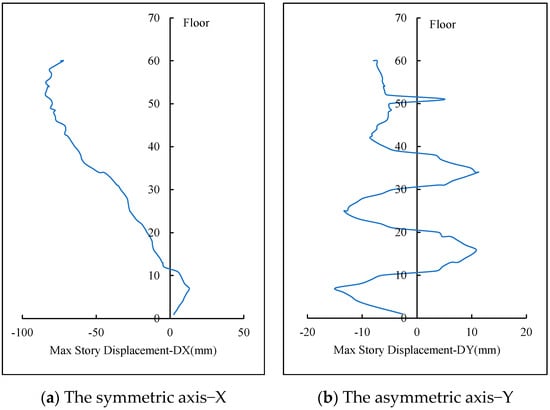
Figure 20.
Max story displacement.
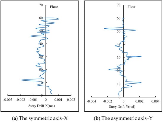
Figure 21.
Story drift.
It could be seen that an asymmetric pattern of story displacement was observed in the direction of symmetry axis of the plan (X direction), while a symmetric pattern in the direction of the asymmetric axis of the plan (Y direction). It was caused by the asymmetric plan of the structure. As can be seen from Figure 5, the south and north side of the structure were symmetric with respect to the asymmetric direction (from east side to west side). The vertical stiffness and loads of the south and north side were almost identical. Therefore, the lateral displacement caused by the vertical stiffness and loads was not going to be significant. In other words, the lateral displacement in the direction of asymmetric axis (from south side to north side) would be small and close to symmetric. Vice versa for the case of the other direction.
The maximum story displacement was found in the 52nd floor in the X direction, which was 84.38 mm. And the maximum story displacement in the Y direction was much smaller than that in the X direction, which was only 13.32 mm taking place in the 25th floor.
Same pattern was found in terms of story drift in the X and Y directions. The maximum story drift in the X direction was found in the 12nd floor, which was 0.00194 rad. The maximum story drift in the Y direction was a little larger, which was 0.00237 rad, happened in the 52th floor.
7.2. Vertical Displacement Difference
Meanwhile, the simulation results of vertical displacement difference (VDD) were obtained and drawn in Figure 22, which indicated that VDDs in the southeast and northeast corners of the structure were larger than that in the southwest and northwest corners. The maximum VDD was found in the 5th section of east side, which was 53.52 mm.
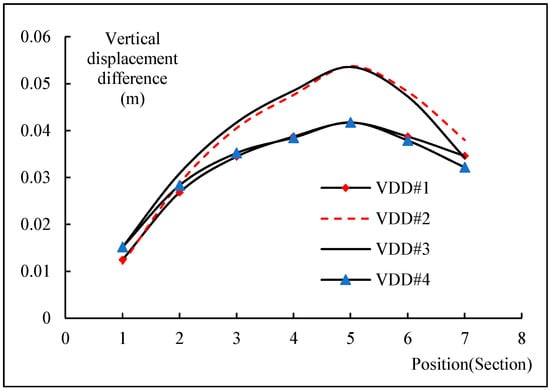
Figure 22.
Simulation results of VDD.
7.3. Stress of Key Components
The analysis results indicated that the maximum stress of mega braces at the south side was approximately 195 MPa, 206 MPa in the north side, and 190 MPa in the east side, as shown in Figure 23. The stresses of all mega braces were all smaller than the yielding strength, since the mega braces were made from Q345GJC steel.
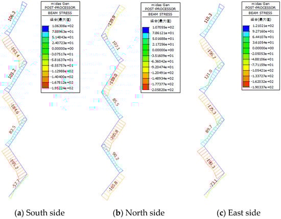
Figure 23.
Stress contour of mega braces.
And the maximum stress of the lower belt truss was approximately 374 MPa, and 337 MPa of the upper belt truss, as shown in Figure 24. They were also both below their yielding strength limit, since belt trusses were fabricated using Q460D steel, manufactured by Bao Steel from Shanghai in China.
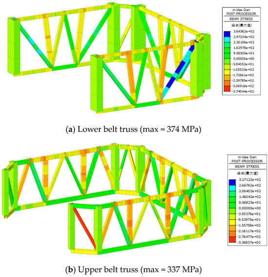
Figure 24.
Stress contour of belt trusses.
8. Deformation Monitoring and Comparison with Simulation during Construction
8.1. Monitoring Plan
- (1)
- Lateral displacement monitoring
The lateral displacement monitoring of Guangzhou Business Center used a combination of equipment, including the total station, inclinometer, static leveling instrument, and GNSS method. During construction, due to the characteristics of the structure and restraining of site environment, single monitoring equipment or technique cannot meet the requirements for displacement monitoring any longer.
Therefore, monitoring control network was first established around the building’s perimeter, using the reference points of the network as a baseline. Reflective prisms are placed on the two external mega columns on the east side for monitoring, as shown in Figure 25. Based on the characteristics of the building and construction needs, two points per floor on typical eight floors are established, including F7, F22, F28, F34, F40, F46, F54, and top floor. Additionally, two GNSS points were also set up, as shown in Figure 25.
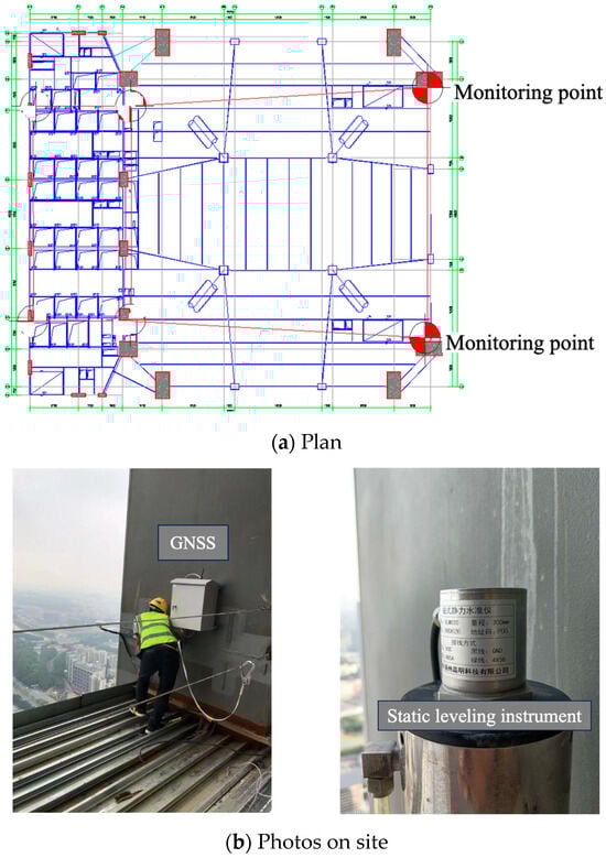
Figure 25.
Lateral displacement monitoring of Guangzhou Business Center.
- (2)
- Vertical displacement monitoring
Guangzhou Business Center, with a height of 375.5 m and a lengthy construction period, would definitely experience significant vertical displacement differences due to the elastic deformation, the shrinkage and creep of the structure during construction.
Due to the visual obstacles in the way of sight, leveling and total stations could not directly view all measurement points inside and outside the building. Therefore, vertical displacement monitoring of the mega columns was performed indirectly.
Firstly, leveling and total station benchmarks were established around the perimeter of the construction area, and monitoring points were designed on the external mega columns in order to measure the absolute deformation values of these columns.
Next, gauges were installed on the corresponding mega columns to monitor the relative vertical displacement difference between them. Displacement monitoring points were arranged on the F7, F22, F34, and F44 floors, as shown in Figure 26.
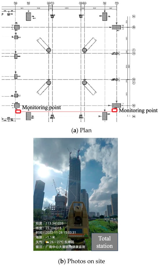
Figure 26.
Vertical displacement monitoring of Guangzhou Business Center.
- (3)
- Strain monitoring of key components
Mega braces were distributed across the south, north, and east facades of the tower. Braces on F1 and F7 were selected with three strain gauges arranged on each brace, as shown in Figure 27.
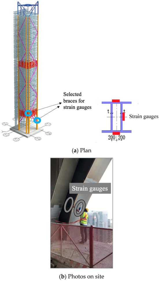
Figure 27.
Strain monitoring of mega braces in Guangzhou Business Center.
8.2. Monitoring Results of Lateral Displacement
By comparing the lateral displacement data between monitoring and simulation, as shown in Figure 28, it could be observed that the simulation was capable of predicting the tendency of lateral displacement of top floor in the X direction to a satisfactory extent of accuracy, along with the increasing number of floors that were finished, although a number of sensors were not working during construction due to the equipment failure. However, there was a relatively large difference in the Y direction, especially when over 45 floors had been constructed. It was mainly because of the stronger wind load during the construction period than that was calculated in the simulation. And the impact of wind force on the lateral displacement was also becoming even more significant since the building was getting higher and higher.
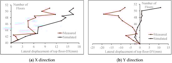
Figure 28.
Comparison between monitoring and simulation results of lateral displacement.
8.3. Monitoring Results of Vertical Displacement
Monitoring results of vertical displacement difference of mega columns at the F7, F22, F34, and F44 floors were also compared with simulation, from which it could be seen that the construction simulation accurately predicted the vertical deformation trends during construction, as shown in Figure 29. In other words, the vertical deformation during the construction period had been well controlled.
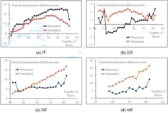
Figure 29.
Comparison between monitoring and simulation results of VDD.
8.4. Monitoring Results of Key Components Strain
From monitoring, strains of mega braces were obtained. Taking the mega braces at the north and east sides on 1F for example, as well as the braces at the south and east sides on 7F as typical comparison objects, strain monitoring results of these braces during construction were compared with the simulation results, as shown in Figure 30.
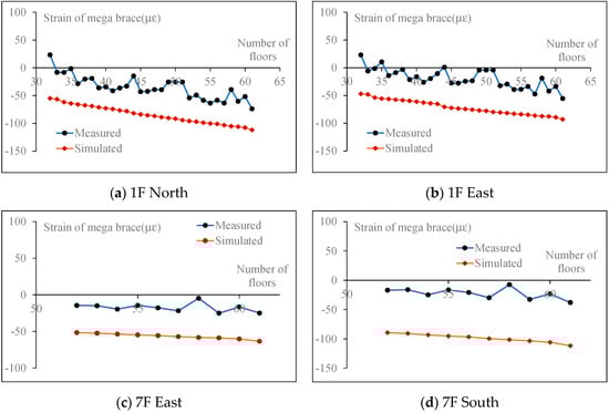
Figure 30.
Comparison between monitoring and simulation results of mega brace strain.
It could be seen that the strain monitoring results were lower than that obtained from simulation, and both strain developing tendencies were similar. Therefore, the predictions based on the simulation results were conservatively safe.
9. Conclusions
Influence of factors such as construction speed, the closure timing of belt trusses and mega braces on the deformation of super high-rise structure with an asymmetric plan during the construction period were parametrically studied in order to bring forward feasible deformation control measurements based on the Guangzhou Business Center project. The effectiveness of the above deformation control measurements was verified through comparison with real-time monitoring results. The following conclusions can then be drawn.
- The construction speed had a minimal impact on the horizontal and vertical deformation of super high-rise steel structures as well as the stress of key components. Therefore, the construction speed should be determined comprehensively by considering the factors such as project schedule, manpower, material resources, natural conditions, and costs.
- When the belt trusses were closed synchronously, the lateral displacement and vertical differences were relatively smaller, compared to the cases of one section and two sections lagging behind. And the maximum stresses of belt trusses were also the lowest. On the other hand, the closure timing had almost no impact on the stress of mega braces. Therefore, it was recommended that belt trusses would better be closed synchronously.
- The closure timing of mega braces had a minimal impact on the vertical displacement difference and the maximum stress of belt trusses. However, the later the braces were closed, the smaller the stress of mega braces, as well as the smaller story drift in the asymmetric axis direction. Therefore, it was recommended that mega braces could be closed with two sections lagging behind.
- The comparison between monitoring and simulation results indicated that the simulation could accurately predict the trends of lateral and vertical deformation during construction. The proposed deformation control measures could effectively manage the structural deformation during the construction period.
Author Contributions
H.-P.W.: conceptualization, formal analysis, funding acquisition, writing—original draft; Y.-Q.X.: investigation, methodology, resources, supervision, writing—review & editing. All authors have read and agreed to the published version of the manuscript.
Funding
This research was funded by the Science and Technology Research and Development Projects of China Construction Eighth Engineering Division Corp., Ltd. (No. 2022-NF-3).
Data Availability Statement
Some or all data that support the findings of this research are available from the corresponding author upon reasonable request.
Conflicts of Interest
Author Hua-Ping Wang was employed by the company China Construction Eighth Engineering Division Corp., Ltd. The remaining author declares that the research was conducted in the absence of any commercial or financial relationships that could be construed as a potential conflict of interest. The authors declare that they have no known competing financial interests or personal relationships that could have appeared to influence the work reported in this paper. Hua-Ping Wang is employee of China Construction Eighth Engineering Division Corp., Ltd., who provided funding and technical support for the work. The funder had no role in the design of the study; in the collection, analysis, or interpretation of data, in the writing of the manuscript, or in the decision to publish the results.
References
- Jia, H.; Song, Y.; Chen, X.; Liu, S.; Zhang, B. Seismic performance evaluation of a high-rise building with structural irregularities. Buildings 2022, 12, 1484. [Google Scholar] [CrossRef]
- Wang, M.; Nagarajaiah, S.; Sun, F.-F. Dynamic characteristics and responses of damped outrigger tall buildings using negative stiffness. J. Struct. Eng. 2020, 146, 04020273. [Google Scholar] [CrossRef]
- Wang, M.; Sun, F.; Koetaka, Y.; Chen, L.; Nagarajaiah, S.; Du, X. Frequency independent damped outrigger systems for multi-mode seismic control of super tall buildings with frequency independent negative stiffness enhancement. Earthq. Eng. Struct. Dyn. 2023, 52, 2731–2754. [Google Scholar] [CrossRef]
- Cao, X.Y.; Shi, J.; Xu, J.G.; Ji, E.; She, Y.; Wang, Z. The combined influence of bond–slip and joint-shear in the seismic upgrading via externally–attached BFRP-bar reinforced precast sub-frames. J. Build. Eng. 2023, 80, 107984. [Google Scholar] [CrossRef]
- Wang, M.; Nagarajaiah, S.; Sun, F. A novel crosswind mitigation strategy for tall buildings using negative stiffness damped outrigger systems. Struct. Control Health Monit. 2022, 29, e2988. [Google Scholar] [CrossRef]
- Wang, H.T.; Tang, C.; Chen, M.S.; Shi, J.; Cao, X.Y. Experimental study on the flexural performance of prestressed RC beams with post-tensioned CFRP strands. Eng. Struct. 2024, 309, 118118. [Google Scholar] [CrossRef]
- Cao, X.Y.; Wu, G.; Feng, D.C.; Wang, Z.; Cui, H.R. Research on seismic retrofitting performance of RC frames using SC-PBSPC BRBF sub-structures. Earthq. Eng. Struct. Dyn. 2020, 49, 794–816. [Google Scholar] [CrossRef]
- Sun, W.; Chen, W.; Long, Y. Monitoring and analysis of settlement and deformation status of high-rise buildings based on nonlinear regression. Meas. Sens. 2024, 35, 101287. [Google Scholar] [CrossRef]
- Zhou, K.; Duan, M.-G.; Wu, Z.-L.; Zhi, L.-H.; Hu, F. Dynamic behavior monitoring of twin supertall buildings during Super Typhoon Soksuri using social sensing data. J. Build. Eng. 2024, 95, 110119. [Google Scholar] [CrossRef]
- Huang, Y.; Feng, R.; Zhong, C.; Tong, X.; Shao, X.; Gu, L.; Hui, Z. Computer vision-based real-time deflection monitoring of complex and sizeable steel structures. Eng. Struct. 2024, 305, 117752. [Google Scholar] [CrossRef]
- Zhou, Y.; Luo, X.; Zhang, W.; Ye, P.; Chen, J.; Du, Z. Improvement of axial deformation prediction in high-rise buildings with field monitoring and adaptive unscented Kalman filter. J. Build. Eng. 2024, 83, 108432. [Google Scholar] [CrossRef]
- Zhang, H.; Shan, J.; Lu, X. Field testing and performance evaluation of AMD-controlled high-rise building structures with real-world validation. J. Build. Eng. 2023, 80, 108109. [Google Scholar] [CrossRef]
- Brownjohn, J.M.W. Structural health monitoring of civil infrastructure. Philos. Trans. R. Soc. A Math. Phys. Eng. Sci. 2007, 365, 589–622. [Google Scholar] [CrossRef]
- Brownjohn, J.M.W.; Pan, T.C.; Deng, X.Y. Correlating dynamic characteristics from field measurements and numerical analysis of a high-rise building. Earthq. Eng. Struct. Dyn. 2000, 29, 523–543. [Google Scholar] [CrossRef]
- Gao, F.; Zhou, H.; Liang, H.; Weng, S.; Zhu, H. Structural deformation monitoring and numerical simulation of a supertall building during construction stage. Eng. Struct. 2020, 209, 110033. [Google Scholar] [CrossRef]
- Vijayan, V.; Santhi, M.H.; Mohan, R. Seismic performance of high rise buildings with different types of shear wall. IOP Conf. Ser. Mater. Sci. Eng. 2020, 936, 012055. [Google Scholar] [CrossRef]
- Wang, M.; Liu, C.; Zhao, M.; Sun, F.-F.; Nagarajaiah, S.; Du, X.-L. Damping dissipation analysis of damped outrigger tall buildings with inerter and negative stiffness considering soil-structure-interaction. J. Build. Eng. 2024, 88, 109225. [Google Scholar] [CrossRef]
- Xiong, H.; Chen, J.; Ventura, C. Seismic fragility analysis of a high-rise concrete-wood hybrid structural system. In Proceedings of the 17th World Conference on Earthquake Engineering, Sendai, Japan, 13–18 September 2020. [Google Scholar]
- Zhu, H.; Gao, K.; Xia, Y.; Gao, F.; Weng, S.; Sun, Y.; Hu, Q. Multi-rate data fusion for dynamic displacement measurement of beam-like supertall structures using acceleration and strain sensors. Struct. Health Monit. 2019, 19, 520–536. [Google Scholar] [CrossRef]
- Liang, Z.S.; Han, L.H. Trussed concrete-filled steel tubular hybrid structures subjected to axial compression: Performance and design calculation. Eng. Struct. 2024, 302, 117465. [Google Scholar] [CrossRef]
- Azandariani, M.G.; Gholami, M. Seismic fragility investigation of hybrid structures BRBF with eccentric-configuration and self-centering frame. J. Constr. Steel Res. 2022, 196, 107300. [Google Scholar] [CrossRef]
- Cao, X.-Y.; Feng, D.-C.; Wang, C.-L.; Shen, D.; Wu, G. A stochastic CSM-based displacement-oriented design strategy for the novel precast SRC-UHPC composite braced-frame in the externally attached seismic retrofitting. Compos. Struct. 2023, 321, 117308. [Google Scholar] [CrossRef]
- Jia, M.; Lu, D.; Guo, L.; Sun, L. Experimental research and cyclic behavior of buckling-restrained braced composite frame. J. Constr. Steel Res. 2014, 95, 90–105. [Google Scholar] [CrossRef]
- Yan, J.-B.; Fan, J.; Ding, R.; Nie, X. Steel-concrete-steel sandwich composite structures: A review. Eng. Struct. 2024, 302, 117449. [Google Scholar] [CrossRef]
Disclaimer/Publisher’s Note: The statements, opinions and data contained in all publications are solely those of the individual author(s) and contributor(s) and not of MDPI and/or the editor(s). MDPI and/or the editor(s) disclaim responsibility for any injury to people or property resulting from any ideas, methods, instructions or products referred to in the content. |
© 2024 by the authors. Licensee MDPI, Basel, Switzerland. This article is an open access article distributed under the terms and conditions of the Creative Commons Attribution (CC BY) license (https://creativecommons.org/licenses/by/4.0/).