Abstract
In order to enhance the self-centering capacity of steel frame structures after earthquakes and reduce the tubes of traditional double-tube or triple-tube SC-BRB, an innovative single-tube self-centering buckling restrained brace (ST-SC-BRB) is proposed in this paper. Firstly, the structural configuration of the ST-SC-BRB component was described. Then, cyclic tests were conducted on one small-scaled BRB and one ST-SC-BRB with the same core steel plate. The test results indicate that the ST-SC-BRB specimen exhibits an excellent self-centering ability compared to the conventional BRB. However, their energy-dissipation capacities are still determined by the core steel plate. In addition, time–history analyses were conducted to evaluate the seismic performance of steel frame structures with BRBs and ST-SC-BRBs. The results suggest that the ST-SC-BRBs can effectively reduce the residual deformation of steel frame structures after earthquakes and contribute to the self-centering capacity of the steel frame structures. Finally, the influence of design parameters of ST-SC-BRB components on the seismic performance of steel frame structures was discussed. It is confirmed that the initial stiffness of the ST-SC-BRB component significantly influences the seismic response of the structure, while the self-centering ratio of the ST-SC-BRB component is a crucial factor in determining the residual deformations of the structure.
1. Introduction
In buildings, traditional buckling restrained braced (BRB) components are employed to resist horizontal forces such as earthquakes or wind loads [1,2,3,4]. When the axial force exceeds the yield load of the BRB components, it undergoes a significant plastic deformation to dissipate the energy, thereby reducing structural damage [5]. However, large residual deformations of post-earthquake structures will increase the cost of structural maintenance. To minimize structural damage, the self-centering BRB (SC-BRB) components have been implemented [6]. The SC-BRB components can dissipate energy and return to their initial position after earthquake loads, representing a novel and promising approach to control structural damage in seismic design [7,8].
SC-BRB components comprise a conventional BRB component for energy dissipation and a pre-tensioned (PT) system for self-centering. Some scholars have investigated the mechanical characteristics of SC-BRB components. The general consensus is that the PT system is a critical factor in achieving the self-centering function of SC-BRB components [9,10]. Miller et al. [11] proposed an SC-BRB based on shape memory alloy rods, and the experimental results indicate that the brace showed a full flag-shape hysteresis curve, a good energy-dissipation capacity, and an outstanding self-centering capacity. Similarly, steel tendons and fiber-reinforced polymer tendons have been used in PT systems [12]. Although SC-BRBs are considerably effective in making a structure resist an earthquake and achieve structural self-centering ability, the problem is that most existing SC-BRBs consist of dual-tube or multi-tube components for PT system, in which two or three functional tubes are in parallel to the core energy-dissipation system. In recent years, a larger number of scholars have made significant achievements in exploring self-centering BRBs, which has further matured the structural design of SC-BRBs [13,14].
In addition, some scholars have investigated the seismic performance of steel frame structures with SC-BRBs. Nazarimofrad et al. [15] carried out time–history analyses of steel frame structures with SC-BRBs, and the analysis results showed that braces with SMA rods can significantly improve the self-centering capacity of the frame structure after earthquake loads. Similarly, Ghowsi et al. [16] performed time–history analyses of the steel frame structure with BRBs and SC-BRBs, respectively. The results showed that the SC-BRBs can effectively reduce the residual deformation of the steel frame structure after earthquake loads but make the frame structure obtain a larger inter-story displacement compared to that of the steel frame structure with BRBs. Moreover, Zhang et al. [17] investigated the impact of post-yield stiffness in SC-BRBs on the seismic performance of frame structures. The results show that increasing the post-yield stiffness of SC-BRBs can effectively reduce the maximum displacement of the lower floors but will cause the vibration effect of higher-order modes on the seismic response of the structure. Summing up, the previous studies have only focused on the seismic response of steel frames with new SC-BRBs, thus limited research has been conducted on the influence of the design parameters of SC-BRBs on structural seismic responses.
In the current state of the art, SC-BRBs are mostly multi-tube structures, meaning the PT system is created using two or three steel tubes and slotted end plates. Considering the drawbacks of the traditional multi-tube SC-BRBs, an innovative ST-SC-BRB is proposed to enhance the self-centering capacity of steel frame structures after earthquakes. To investigate the seismic performance of the proposed SC-BRB and its efficiency in enhancing the seismic resistance and self-centering ability of frame structures, the configuration of the proposed ST-SC-BRBs is first described. Then, cyclic tests were conducted on one small-scaled BRB and one ST-SC-BRB. In addition, time–history analyses were conducted to evaluate the seismic performance of the steel frame structures with BRBs and ST-SC-BRBs. Finally, the influence of design parameters of the ST-SC-BRB components on the seismic performance of the structure was discussed.
2. Configuration of New ST-SC-BRB
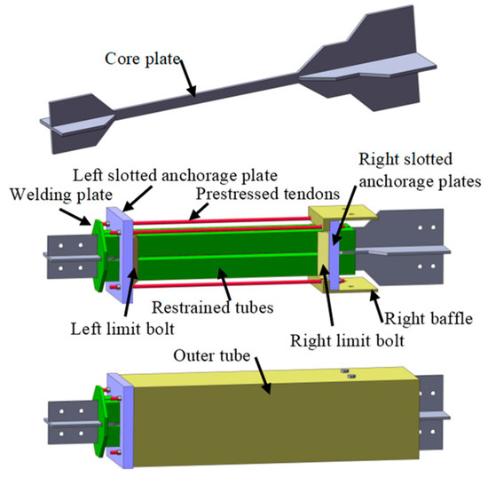
The new ST-SC-BRB has a typical all-steel BRB, as the energy-dissipation system is connected in parallel to the glass fiber-reinforced polymer (GFRP) rods as a PT system with only one outer tube. Figure 1 illustrates the assembly of the new ST-SC-BRB. The restraint tube is welded to the left end of the core steel plate and provides lateral buckling restraint for the core steel plate. The outer tube is welded to the right end of the core steel plate and bolted to the right baffle. When the GFRP rods are pretensioned, the anchorage plates are pressed and generate compression in the restrained tube and outer tube.
Figure 1.
Configuration of the ST-SC-BRB.
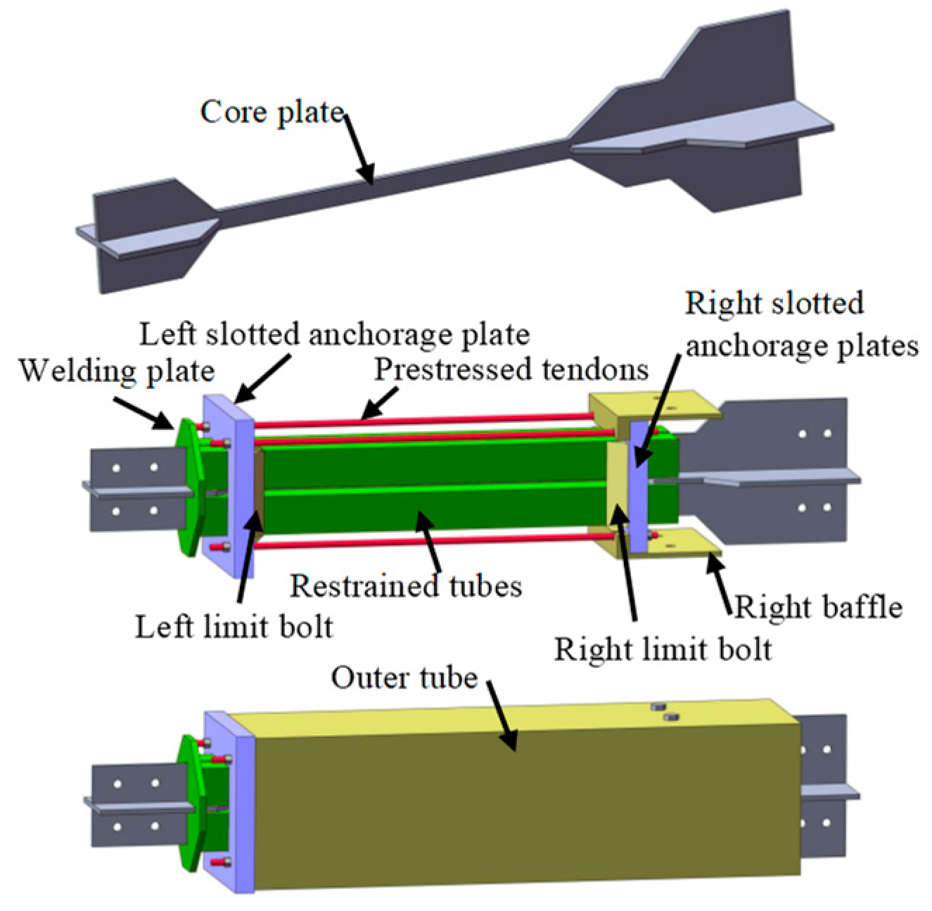
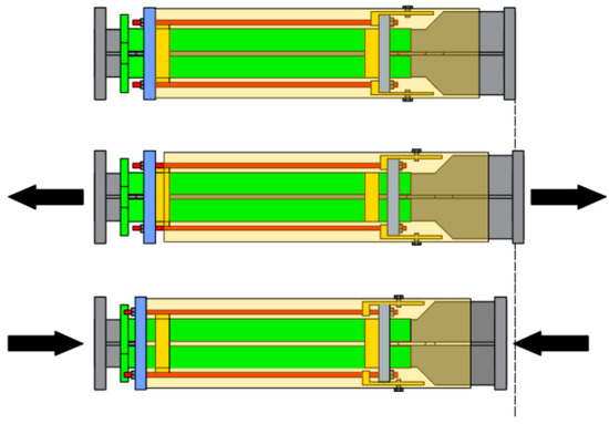
As shown in Figure 2, when the ST-SC-BRB component is subjected to compression, the outer tube and the restrained tube move outward at the free end, driving left- and right-slotted anchorage plates of the PT system outward, thereby generating restoring force. On the contrary, when the ST-SC-BRB component is subjected to tension, the welded end of the outer tube and the restrained tube move outward, driving left and right slotted anchorage plates of the PT system outward, also generating restoring force. Generally, when the ST-SC-BRB is under either compression or tension, the displacement of the anchorage plates leads to an additional elongation of the GFRP rods and an increase in the force applied to the GFRP rods.
Figure 2.
Principle of the ST-SC-BRB.
3. ST-SC-BRB Experimental Program
3.1. Brace Design and Testing Protocol
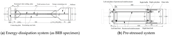
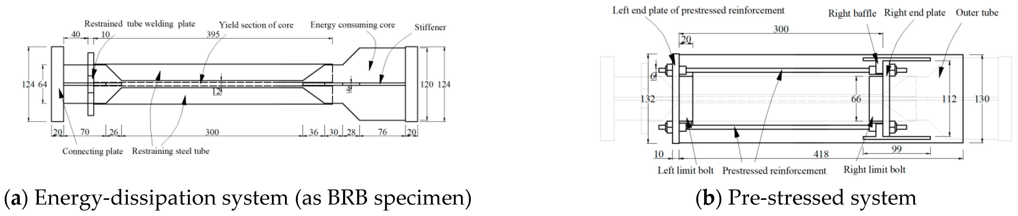
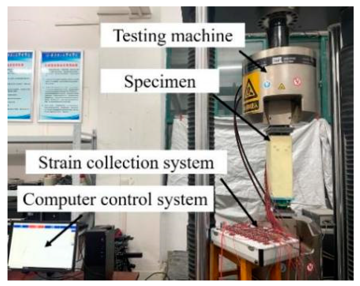
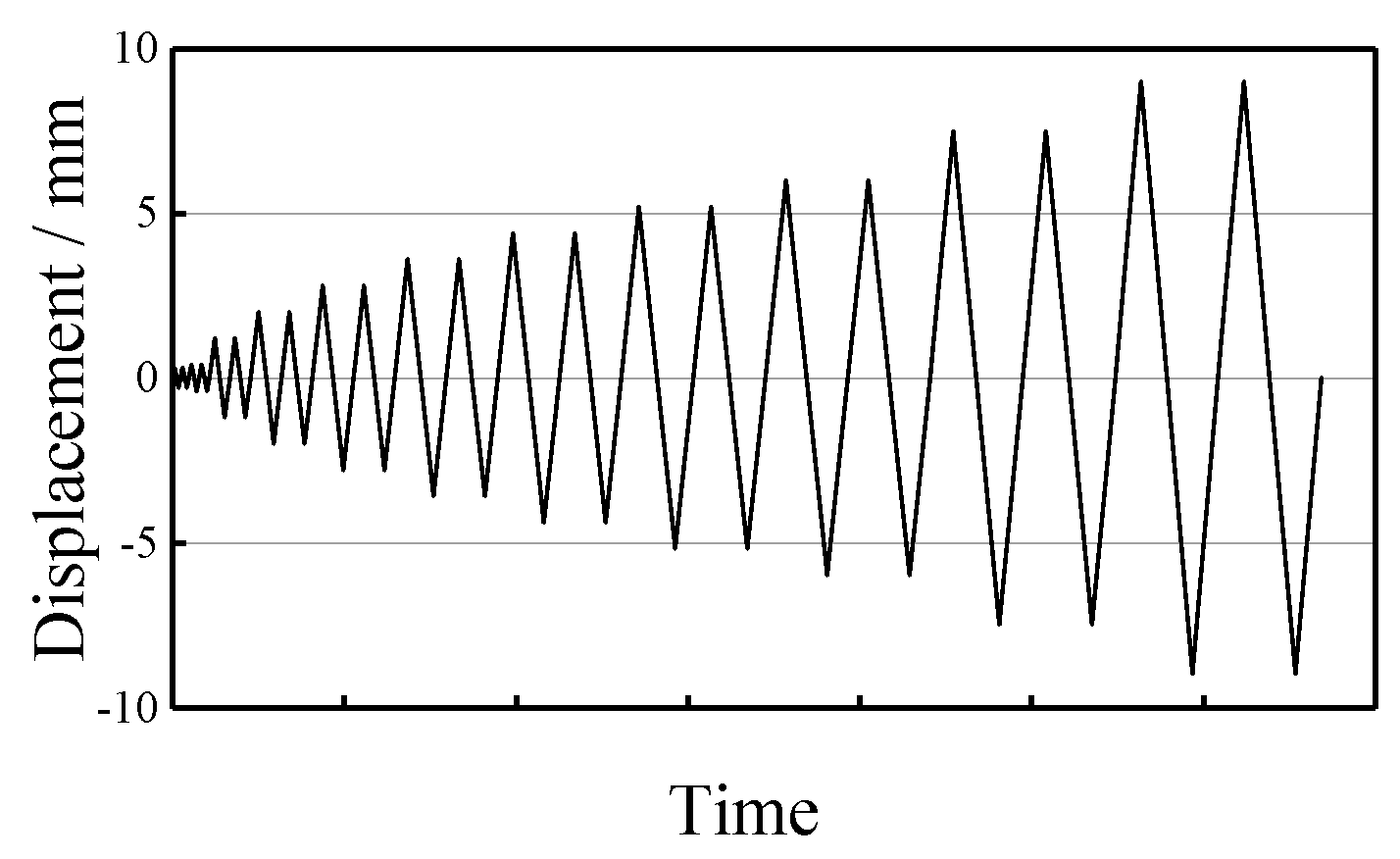
In order to investigate the mechanical properties of the new ST-SC-BRB, a small-scaled steel BRB specimen and ST-SC-BRB specimen were made by Q235 steel with a core steel plate of the same size. The typical BRB specimen was designed based on the previous model by Koetaka et al. [18], as shown in Figure 3a. The PT system of the ST-SC-BRB specimen has adopted GFRP rods with a tensile strength of 680 MPa. The self-centering ratio ξ (ratio of pre-stressed tendons to yield load of core energy-dissipating steel plates) of the ST-SC-BRB specimen is set to 1. The specific dimensions of the specimens are designated in Figure 3. The dimensions are listed in Table 1. The specimens were tested by a 100 t MTS universal testing machine as shown in Figure 4, under a displacement-based loading algorithm with incremental amplitudes as shown in Figure 5. The loading amplitude is Δ0, 3Δ0, 5Δ0, 7Δ0…… (Δ0 is the yield displacement of the core, taken as 0.4 mm). Once the displacement reaches 6 mm, the load span changes to 1.5 mm until failure. The loading rate of the first cycle is 0.01 mm/s, and then the loading rate is increased to 0.02 mm/s.
Figure 3.
Dimensions of BRB and ST-SC-BRB (unit: mm).
Table 1.
Dimensions of components of brace (Unit: mm).
Figure 4.
Test setup.
Figure 5.
Loading protocol of test.
3.2. Test Results and Discussion
3.2.1. Test Observations
For the two specimens, there was no overall buckling during the test. Moreover, as the test progressed, collision sounds caused by the friction between the steel core plate and the restraining tube were heard. When the loading displacement increased, the steel core plate locally buckled and local bulging could be observed in the steel tube.
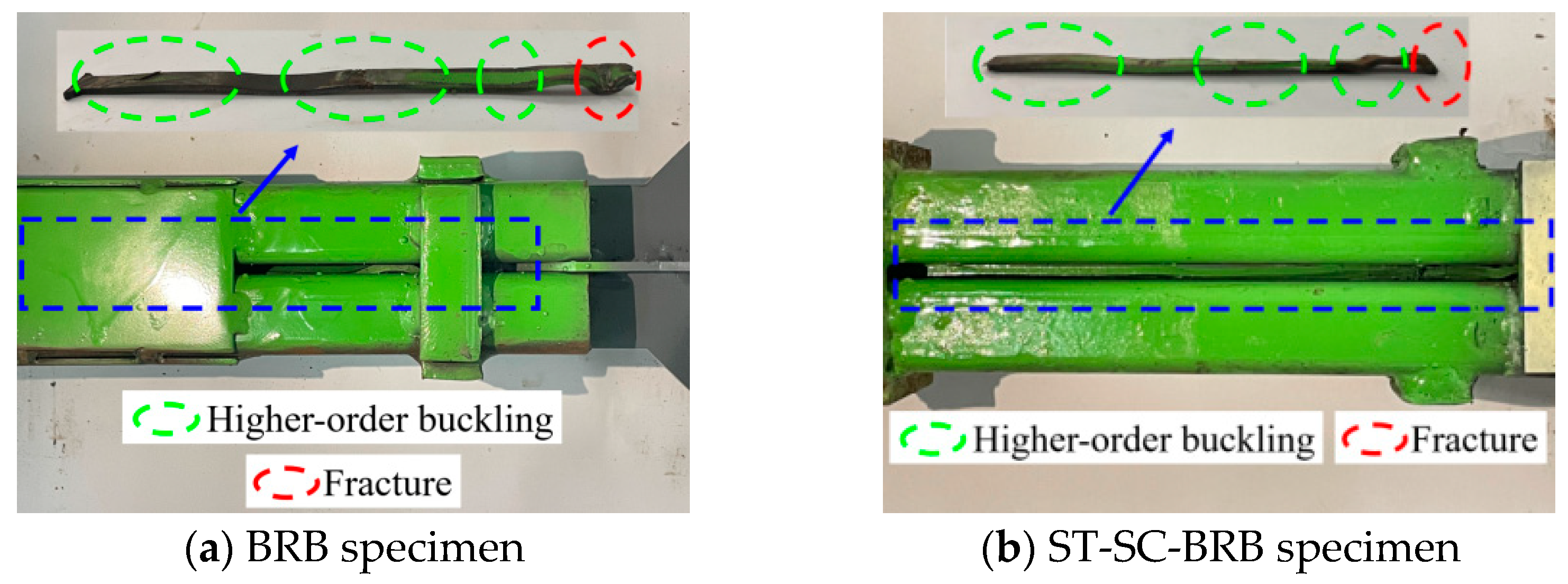
When the BRB specimen was subjected to compression loading up to 8 mm and then unloaded, the end of its core steel plate suddenly fractured, and the test was terminated, as shown in Figure 6a. For the ST-SC-BRB specimen, when first loaded to about 8.7 mm, a bang sound occurred, followed by a continuous popping sound, and then the loading capacity significantly declined. The last loading cycle was reached with a bang sound and the test was terminated, indicating the failure of the ST-SC-BRB specimen, as shown in Figure 6b.
Figure 6.
Failure mode of the two specimens.
3.2.2. Hysteresis Behavior
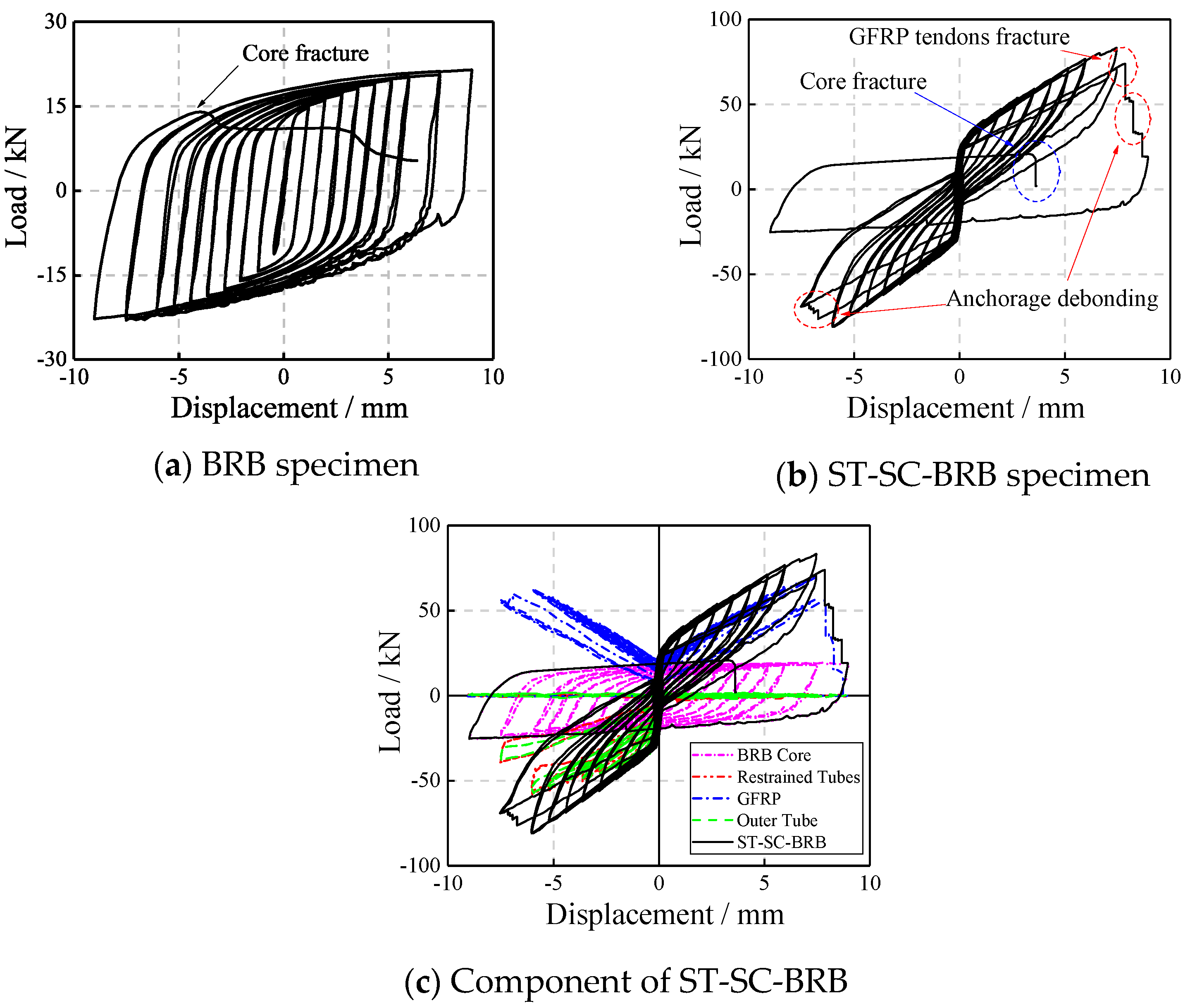
Figure 7 shows the axial load-displacement behavior of the two specimens. The BRB specimen exhibited a full hysteretic curve and sufficient energy-dissipation capacity as illustrated in Figure 7a. The axial load-displacement curve of the ST-SC-BRB specimen shows a typical flag shape, with good self-centering capacity before 8 mm. After that, the brace components started to damage and fail, with distinct anomalies in the curve, as seen in Figure 7b. Figure 7c shows the axial load of each component and displacement curves of the ST-SC-BRB specimen. As can be found, whether the specimen is under tension or compression, the GFRP tendons are in a tension state to provide restoring force for the specimen. Meanwhile, because of a combination of the strain hardening of the BRB core, the debonding of the anchorage, and the loss of GFRP pretension, the residual deformation of each loading cycle gradually increased as the loading proceeded.
Figure 7.
Hysteresis curve.
3.2.3. Performance Evaluation
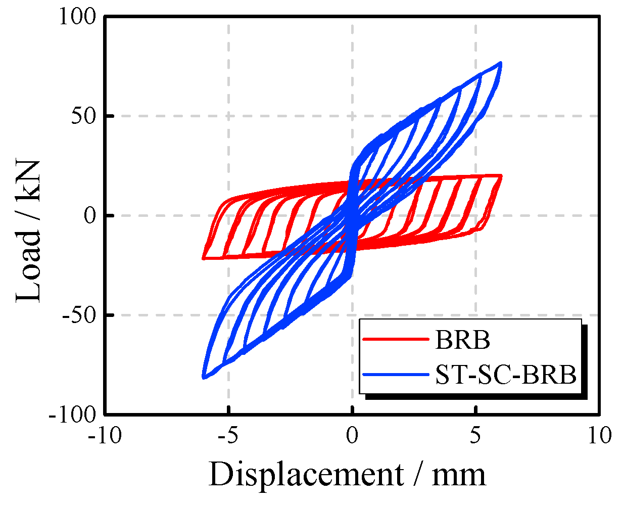
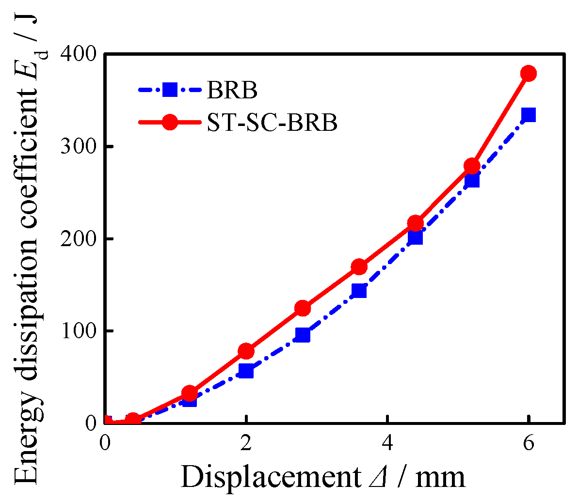
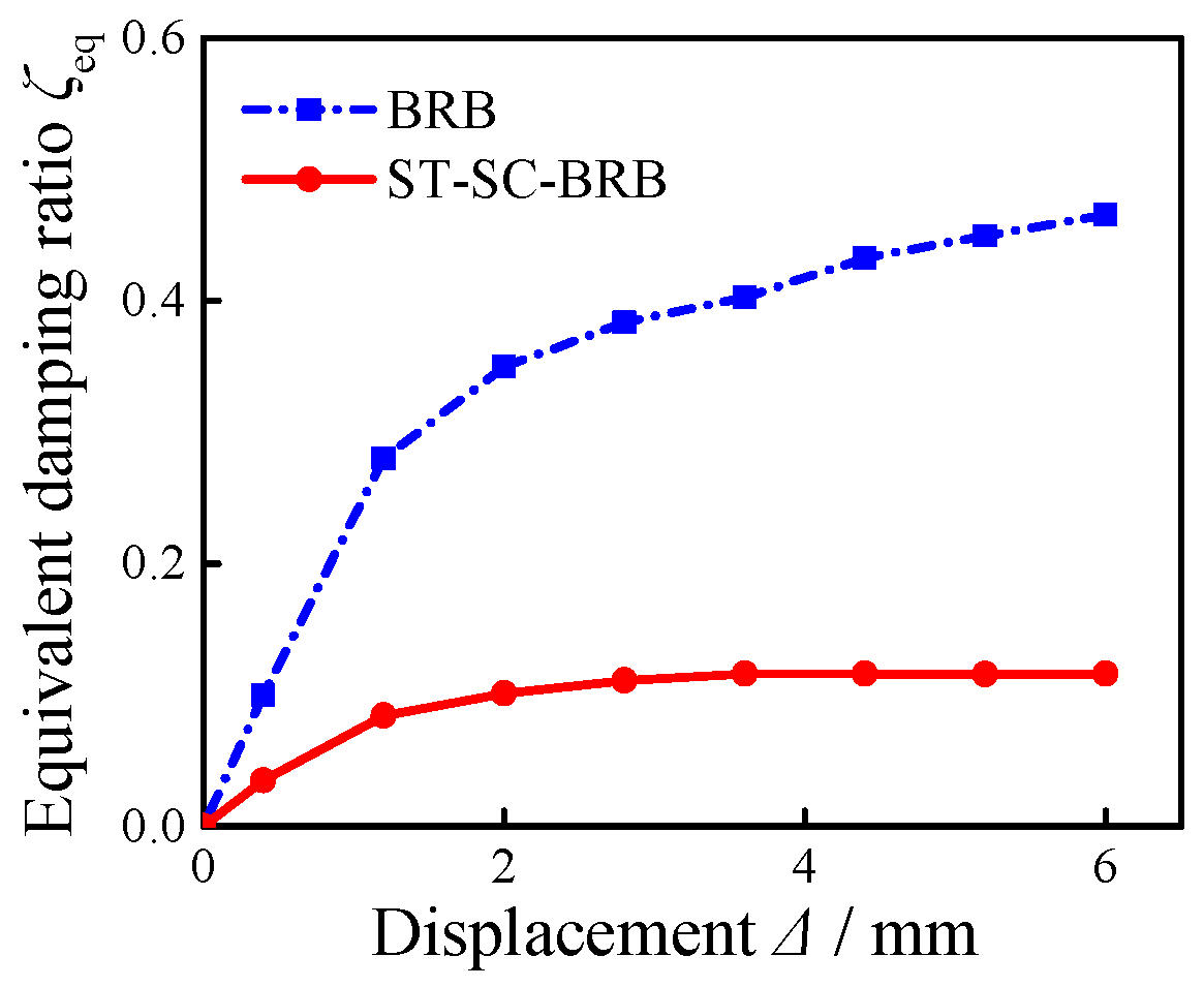
Figure 8 shows the hysteresis curves of the BRB and ST-SC-BRB specimens when the target displacement is less than 8 mm. It can be found that the initial stiffness and the post-yield stiffness of the ST-SC-BRB specimen are greater than that of the BRB specimen, which is caused by the addition of the PT system. At a displacement load of 6 mm, the ST-SC-BRB exhibits a residual deformation of 0.78 mm under tension and −0.84 mm under compression, with an average residual deformation of 0.81 mm, which represents 13.5% of the displacement amplitude. The relationship between the cumulative energy dissipation and the corresponding axial deformation of both specimens is shown in Figure 9. Under the same target displacement, though the cumulative energy dissipation of the ST-SC-BRB specimen is larger than that of the BRB specimen due to the contribution of a PT system, the difference is negligible. This also indicates that the parallel connection of the PT system with the BRB component does not significantly increase the structural energy dissipation capacity, and the structural energy-dissipation capacity is still determined by the core steel plate. Furthermore, due to the significantly increased yield load of the ST-SC-BRB specimen, the equivalent damping ratio is notably reduced compared to the BRB specimen, as shown in Figure 10.
Figure 8.
Hysteresis curve with 8 mm.
Figure 9.
Energy-dissipation coefficient.
Figure 10.
Equivalent damping ratio.
4. Seismic Analysis of Self-Centering Braced Steel Frame Structures
4.1. Structural Model and Design Parameters
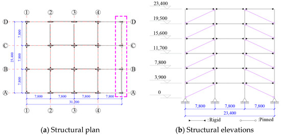
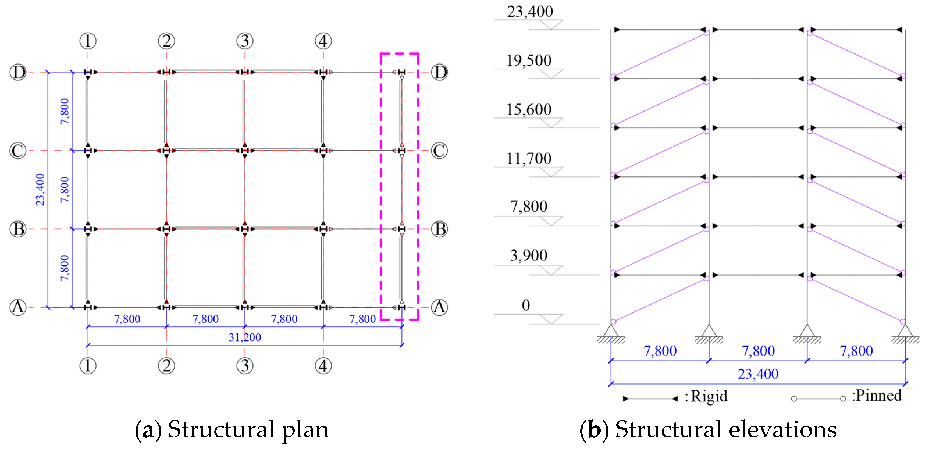
The plan dimension of the frame structure is 31.2 m × 23.4 m, with six floors and each floor height of 3.9 m with a seismic intensity of eight degrees. There are four spans in the east-west direction and three spans in the north-south direction. The structure was designed based on Chinese codes [19], and rigid beam–column connections were adopted. The column bases are fixed to enhance structural seismic robustness. The frame beams and columns used Q235 steel, and the contribution of the floor slabs is ignored. The frame is composed of diagonally pinned N-braces along the height. The structure layout is shown in Figure 11. The dimensions of the structural beams and columns are shown in Table 2. Considering the symmetry of the layout, the span with braces is chosen as a benchmark. The load on the slabs is converted into an equivalent uniform line load and is then applied to the beams.
Figure 11.
Plane and elevation of the steel frame structure.
Table 2.
Section of beams and columns.
The yield capacity of the traditional BRB component is taken as 600 kN, according to the code [19]. The ST-SC-BRB component is assumed to have the same energy-dissipating core and the corresponding yield capacity as the traditional BRB component. To ensure that the brace has sufficient self-centering capacity, the initial pre-stress of the ST-SC-BRB component should be greater than the yield strength of the core steel plate. Then, the area of the energy-dissipating core is determined to be 870 mm2. Each pre-stressing GFRP tendon has a radius of 11.95 mm and an elastic modulus of 28 GPa.
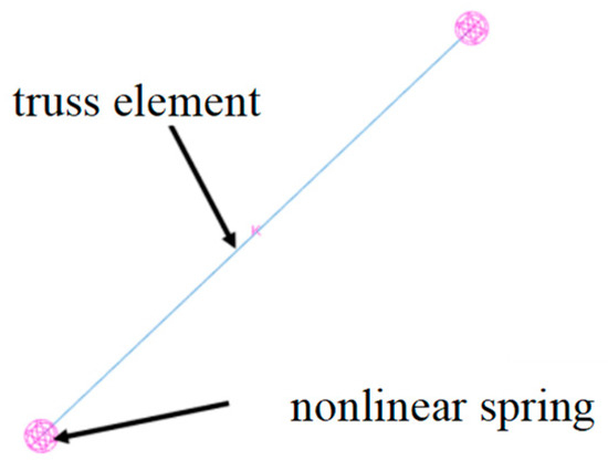
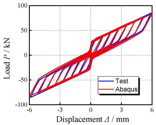
4.2. Simplified Finite Element Model of the Structure
The finite element software ABAQUS 6.14 is used to establish the above numerical model of the braced steel frame. The restoring force model of the ST-SC-BRB component is a superposition of the cyclic hardening model of the steel core and the bilinear elasticity model of the PT system. The ST-SC-BRB component is modeled using a parallel combination of a truss element and a nonlinear spring element, as shown in Figure 12. The comparison between the calculation results obtained using the simplified model and the test result is shown in Figure 13, indicating that the simplified model can better simulate the hysteretic energy-dissipation characteristics and bearing capacity of ST-SC-BRB component.
Figure 12.
Equivalent simplified model.
Figure 13.
Calculated result vs. test result.
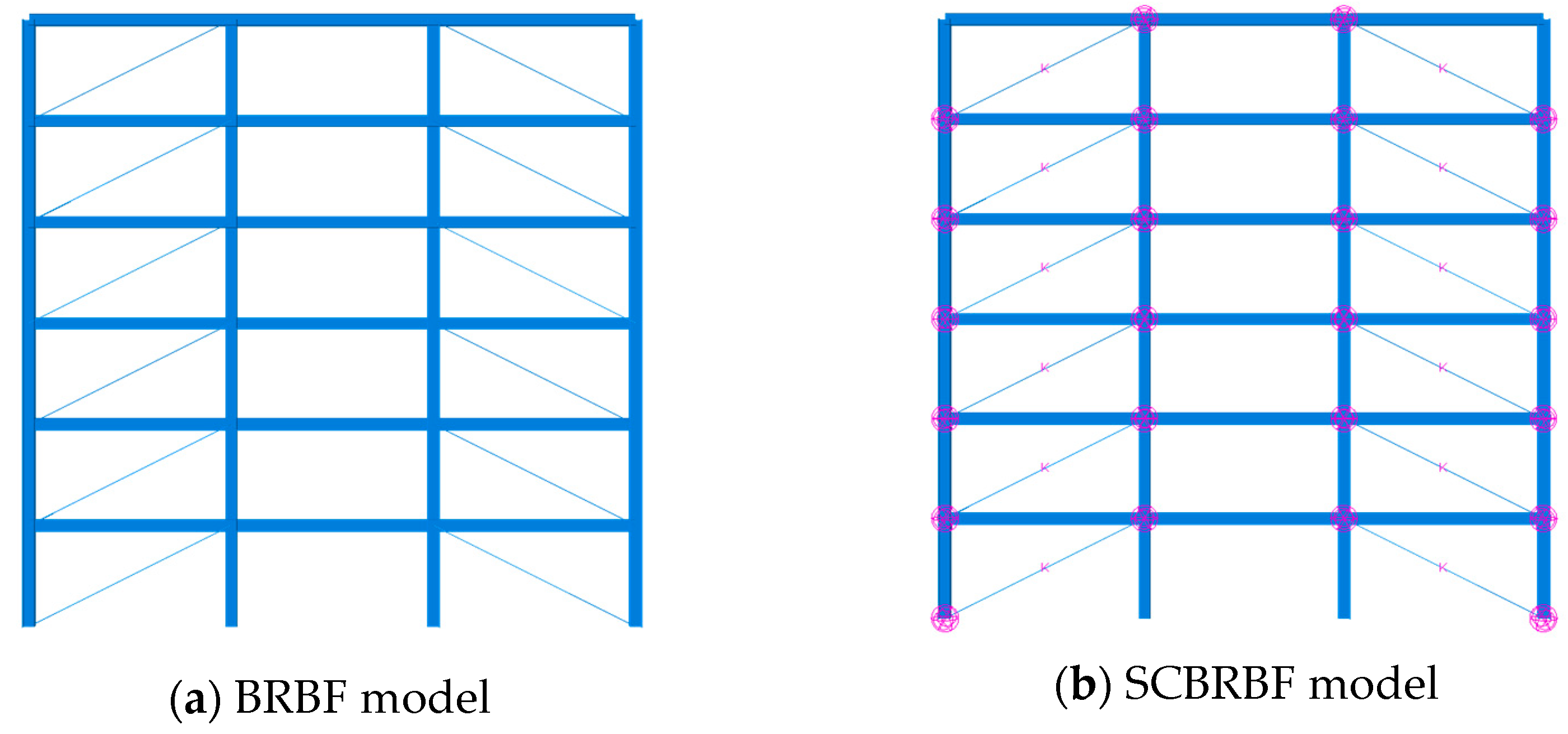
The BRB frame model (BRBF model) and the ST-SC-BRB frame model (SCBRBF model) are developed to evaluate the seismic performance of the steel frame structure. The beams and columns of the main frame structure are modeled by B31 elements, and the beams and columns are stiffened by rigid connections. The BRB component is simulated by T3D2 elements, and the ST-SC-BRB is simulated by the above equivalent simplified model. The braces and the frame are pin connected. The structural model is shown in Figure 14.
Figure 14.
Numerical model of steel frame structures.
4.3. Seismic Wave Selection
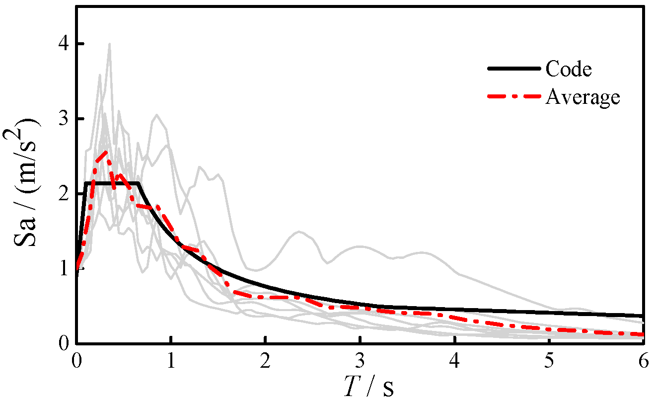
Seven pairs of ground motion records were used, including six natural waves and one artificial wave (El Centro wave, Chi-Chi wave, Imperial Valley wave, Duzce wave, San Fernando wave, Erzincan wave, and artificial Shanghai2 wave, as shown in Table 3). The corresponding acceleration spectrums are compared with the code response spectrum in Figure 15. The peak ground accelerations (PGA) under frequent, design, and rare earthquakes are taken as 70 gal, 200 gal, and 400 gal for the seismic analyses, respectively.
Table 3.
Information of selected earthquake waves.
Figure 15.
Acceleration spectra.
4.4. Analysis of Structural Seismic Performance
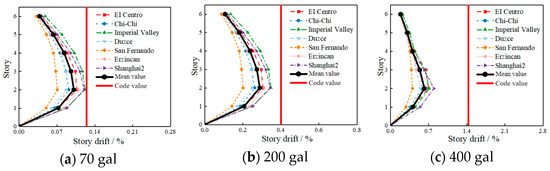
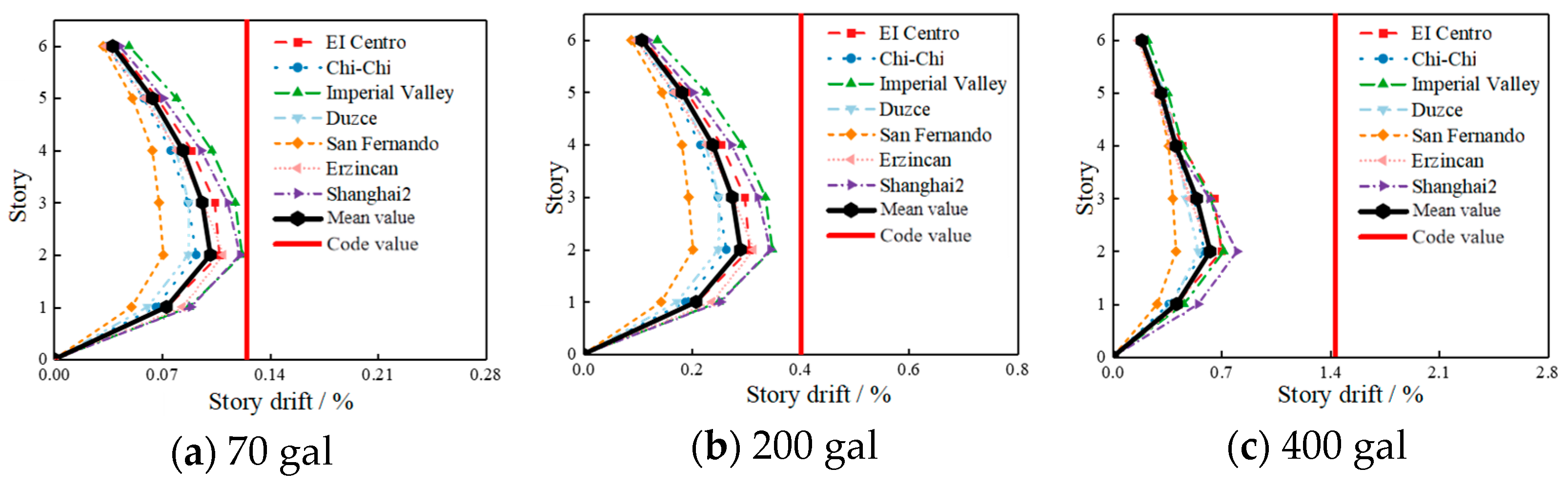
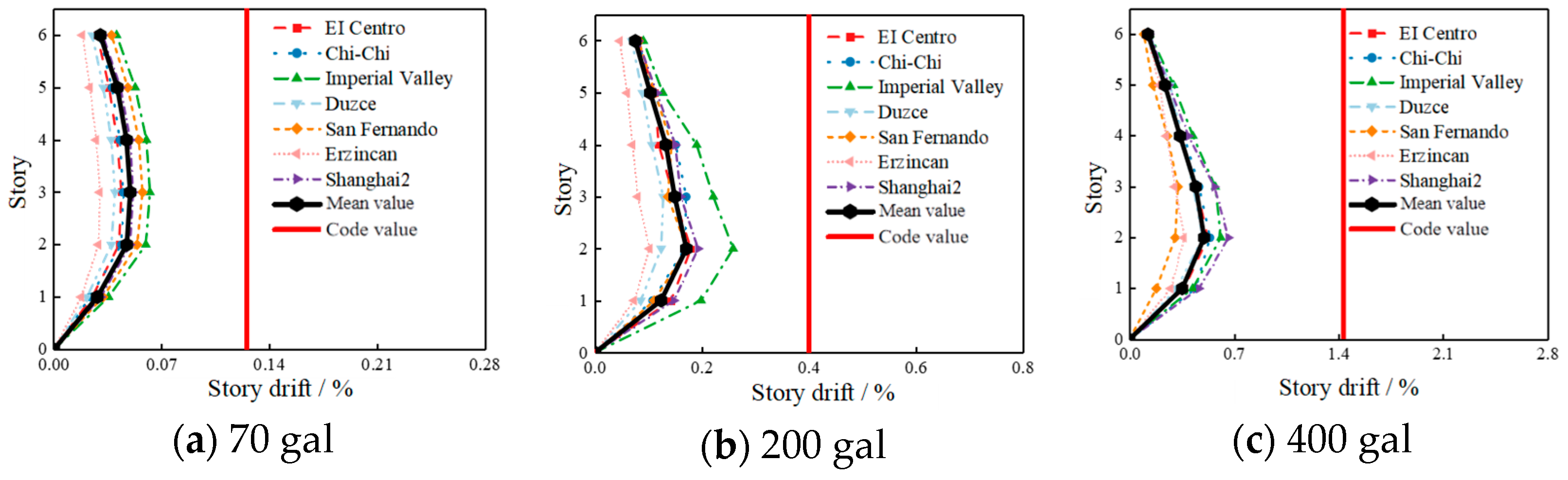
Figure 16 and Figure 17 show the comparison of the maximum story drift between the two structures under different ground motions. It can be found that the maximum story drift of both structures satisfies the code requirements and shows a similar trend. Under rare earthquakes, the maximum story drift of the BRBF reaches 1/125, less than the code requirement of 1/70. Meanwhile, the story drift of the BRBF is generally larger than that of the SCBRBF, because the ST-SC-BRB can provide a higher stiffness after yielding than the traditional BRB. Under frequent earthquakes, compared with the BRBF, the maximum story drift of the SCBRBF is reduced by 72.86% under the Erzincan wave and by 18.76% under the San Fernando wave. However, under rare earthquakes, the maximum story drift of the SCBRBF is only reduced by 41.78% under the Erzincan wave and by 6.80% under the Chi-Chi wave.
Figure 16.
Story drift of BRBF.
Figure 17.
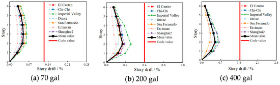
Story drift of SCBRBF.
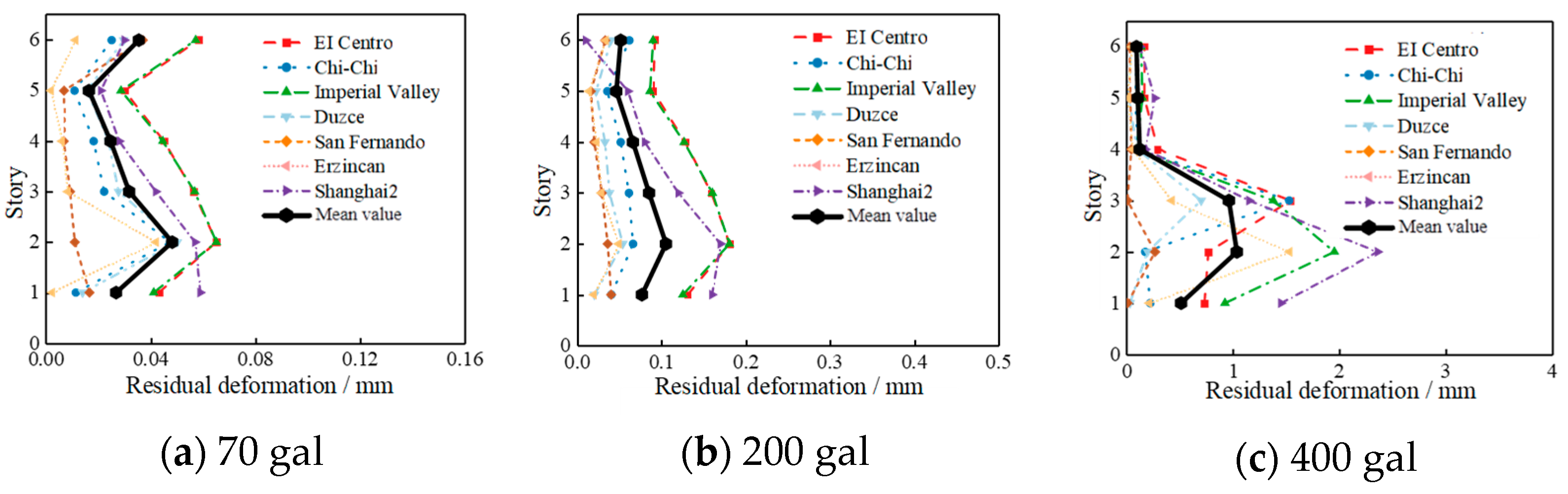
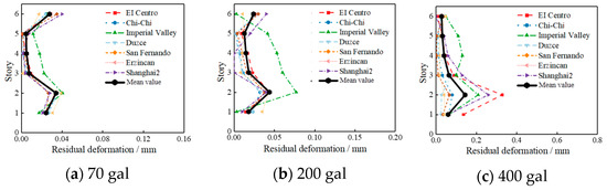
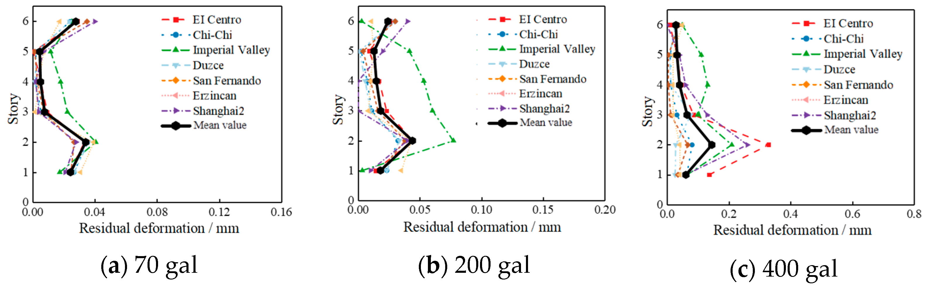
Figure 18 and Figure 19 show the comparison of the residual deformation between the two structures under different ground motions. It can be seen that the maximum residual deformation of the SCBRBF structure is obviously smaller than that of the BRBF, indicating that the ST-SC-BRB plays an important role in controlling the residual deformation of the structure. The controlling effect of the ST-SC-BRB on the residual deformation becomes more pronounced with the PGA increase. Under rare earthquakes, compared with the BRBF, the maximum residual deformation of the SCBRBF is reduced by 74.52–97.32%.
Figure 18.
Residual deformation of BRBF.
Figure 19.
Residual deformation of SCBRBF.
5. Brace Design Parameters on the Seismic Performance of Structures
5.1. Design Parameters of the Brace
The first stiffness, second stiffness, and self-centering ratio of the ST-SC-BRB are chosen as the main parameters to study the seismic response of the SCBRBF frame structure described in Section 4 (notated as SCBRBF-0) under the El-Centro wave with a PGA of 400 gal. The parameter variations are listed in Table 4. The first and second stiffnesses can be modified by changing the stiffness of the nonlinear springs. To change the self-centering ratio, the yield displacements and the corresponding load capacities are modified when the stiffness of the nonlinear springs remains unchanged.
Table 4.
Design parameters of the ST-SC-BRB component in the SCBRBF.
5.2. Results and Discussion
5.2.1. Effect of First Stiffness
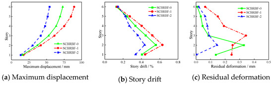
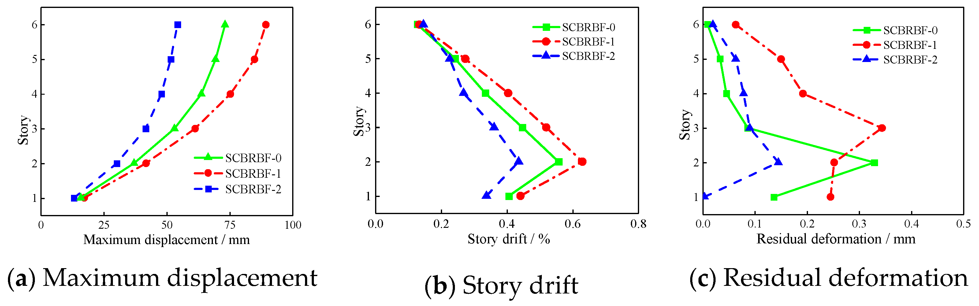
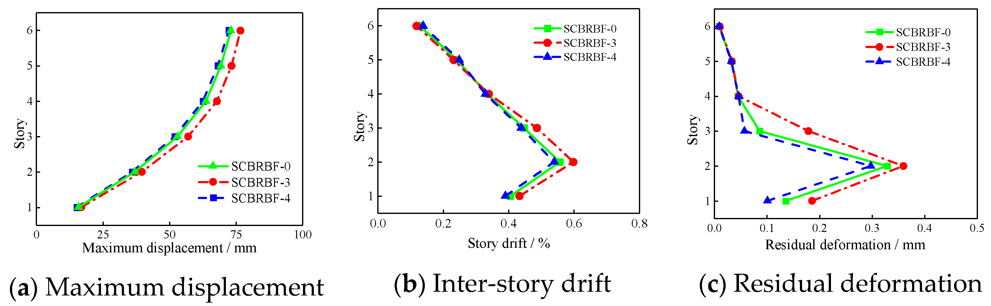
As shown in Figure 20, the first stiffness of SC-ST-BRBs has a significant effect on the maximum displacement of the structure. By increasing the first stiffness of SC-ST-BRBs, the maximum displacement and the story drift of the structure show a decreasing trend. The maximum displacement and inter-story drift ratio of SCBRBF-2, which has a first stiffness three times that of SCBRBF-1, is reduced by 39.32% and 30.84, respectively. However, Figure 20c shows the uncertainty of the effect of the first stiffness on the residual deformation. While the maximum residual deformation of SCBRBF-0 occurs in the second story, that of SCBRBF-1 is in the third story. It should be noted that the value of the first stiffness of the ST-SC-BRB needs to be consistent with the lateral stiffness distribution of the structure otherwise it may result in an undesired seismic response of the structure. The working principle of the ST-SC-BRB determines that the first stiffness depends on the cross-sectional areas of the outer tube and the restraint steel tube as well as the length of the brace.
Figure 20.
First stiffness of ST-SC-BRB.
5.2.2. Effect of Second Stiffness
As shown in Figure 21, the effect of the second stiffness of the ST-SC-BRBs on the seismic performance of the structure is limited, although increasing the second stiffness of the ST-SC-BRBs can reduce the maximum story displacement and story drift of the structure. The second stiffness of the ST-SC-BRB is contributed by the stiffness of the pre-stressed tendons and the energy-dissipating core when the inner and outer tubes undergo relative displacements. Compared with the stiffness of the pre-stressed tendons, the post-yield stiffness of the energy-dissipating inner core is generally much smaller, so the second stiffness can be considered to be the stiffness of the pre-stressed tendons, which is mainly controlled by the cross-sectional area of the pre-stressed tendons and their elastic modulus.
Figure 21.
Second stiffness of ST-SC-BRB.
5.2.3. Effect of Self-Centering Ratio
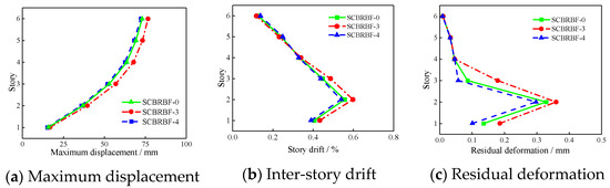
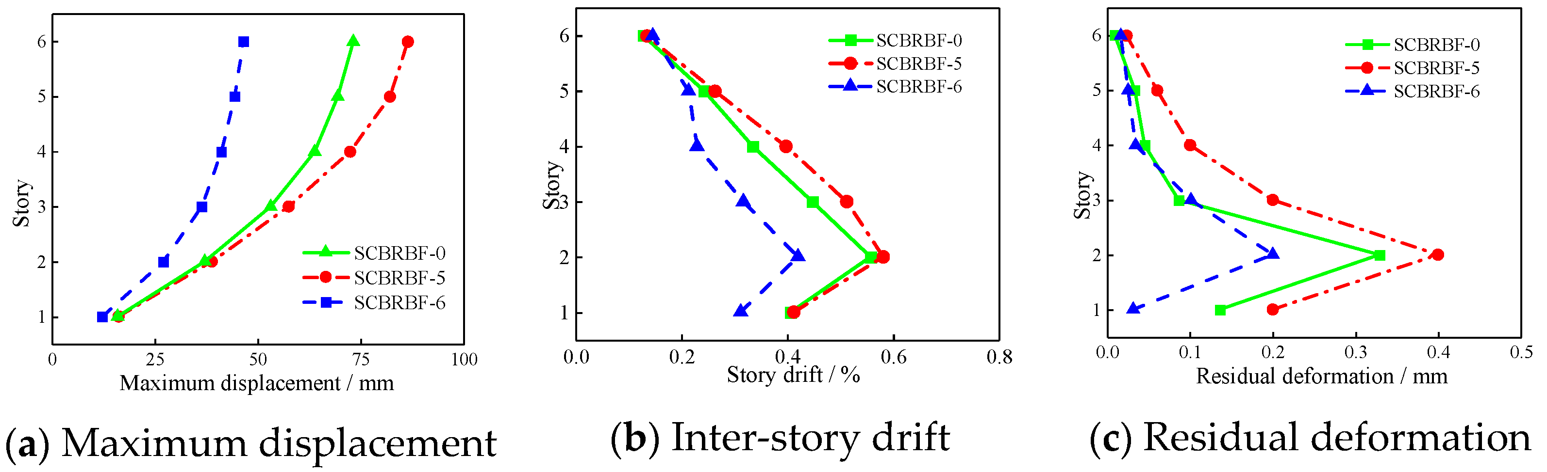
In Figure 22, it can be found that the self-centering ratio has a distinct influence on the seismic response of the structure. As the self-centering ratio increases, the maximum story displacement, the maximum story drift, and the maximum residual deformation of the structure are decreasing, obviously. A 50% increase in the self-centering ratio can lead to a maximum reduction of up to 33.51%, 43.14%, and 39.21%, respectively. The self-centering ratio of the ST-SC-BRB is determined by the ratio of the initial pre-stressing to the yield force of the core steel plate, which plays an important role in controlling the displacement response of the structure, reducing the residual deformation and realizing the self-centering. According to the previous analysis, when the pre-stressing is smaller than the yield force of the inner core, self-centering cannot be realized. Thus, in the design of SCBRBF, the amplitude of the pre-stressing is suggested to equal the value of the yield force of the core steel plate.
Figure 22.
Self-centering ratio of ST-SC-BRB.
6. Conclusions
In this paper, based on the traditional steel BRB, an outer tube is added in parallel to the PT system to form a new type of ST-SC-BRB component. Its mechanical properties and application in the seismic performance of steel frame structures are investigated, and the main conclusions are as follows:
- As the restrained steel tube in the traditional all-steel BRB is used as the inner tube of the PT system, the new ST-SC-BRB component can greatly simplify the construction of the traditional dual-tube or multi-tube SC-BRB.
- The cyclic test results show that the proposed ST-SC-BRB exhibits excellent self-centering ability without significantly increasing its energy-dissipation capacity compared to the conventional BRB. At a displacement load of 6 mm, the ST-SC-BRB exhibits an average residual deformation of 0.81 mm.
- Compared with the steel frame structures with traditional BRBs, the maximum story drift of structures with ST-SC-BRBs under seismic loads is reduced, and the corresponding residual deformation is remarkably reduced by up to 74%.
- The initial stiffness of the ST-SC-BRB component significantly influences the seismic response of the structure, while the self-centering ratio of the ST-SC-BRB component is a crucial factor in determining the residual deformation of the structures. To achieve a better self-centering ability, the self-centering ratio of the ST-SC-BRB should be greater than 1.0.
Author Contributions
Writing—original draft preparation and formal analysis, Y.L.; conceptualization, methodology, and writing—review and editing, Z.Z. and W.H.; test conduction and draft editing, Y.L. and M.S.; draft review and editing, J.L. All authors have read and agreed to the published version of the manuscript.
Funding
This research was funded by the National Natural Science Foundation of China (Grant No. 51974217).
Data Availability Statement
Some or all data, models, or codes generated or used during the study are available from the corresponding author upon request.
Conflicts of Interest
Author Maoyu Shen was employed by the company Sany Renewable Energy Co., Ltd. The remaining authors declare that the research was conducted in the absence of any commercial or financial relationships that could be construed as a potential conflict of interest.
References
- Xu, G.; Guo, T.; Li, A.; Wang, S.; Zhang, R.; Zhu, R.; Xu, J. Review on self-centering damper for seismic resilient building structures. Structures 2023, 54, 58–77. [Google Scholar] [CrossRef]
- Liu, C.; Xu, D. Diagrid Core-tube Structure Seismic Performance Based on Equivalent Stiffness Ratio of Inner and Outer Tubes. KSCE J. Civ. Eng. 2023, 27, 1682–1696. [Google Scholar] [CrossRef]
- Wei, J.G.; Ying, H.D.; Yang, Y.; Zhang, W.; Bao, C.G. Seismic performance of concrete-filled steel tubular composite columns with ultra high performance concrete plates. Eng. Struct. 2023, 278, 115500. [Google Scholar] [CrossRef]
- Deng, E.F.; Wang, Y.H.; Zong, L.; Zhang, Z.; Zhang, J.F. Seismic behavior of a novel liftable connection for modular steel buildings: Experimental and numerical studies. Thin-Walled Struct. 2024, 197, 111563. [Google Scholar] [CrossRef]
- Nuzzo, I.; Losanno, D.; Caterino, N. Seismic design and retrofit of frame structures with hysteretic dampers: A simplified displacement-based procedure. Bull. Earthq. Eng. 2019, 17, 2787–2819. [Google Scholar] [CrossRef]
- Zhou, Y.; Tian, W.; Xiao, Y. Design recommendations for self-centering buckling restrained braces. Eng. Struct. 2022, 273, 115019. [Google Scholar] [CrossRef]
- Huang, W.; Shen, M.; Liu, J.; Wang, L.; Liu, X.; Zhou, Z. Study on seismic performance of an innovative single-tube self-centering buckling-restrained brace. J. Constr. Steel Res. 2023, 211, 108185. [Google Scholar] [CrossRef]
- Liu, J.; Qiu, C.; Zhang, Y.; Liu, H.; Du, X. Hysteretic model and seismic performance of a self-centering brace equipped with energy absorbing steel plate clusters. Structures 2023, 57, 105153. [Google Scholar] [CrossRef]
- Christopoulos, C.; Tremblay, R.; Kim, H.J.; Lacerte, M. Self-Centering Energy Dissipative Bracing System for the Seismic Resistance of Structures: Development and Validation. J. Struct. Eng. 2008, 134, 96–107. [Google Scholar] [CrossRef]
- Hashemi, S.V.; Miri, M.; Rashki, M.; Etedali, S. Multi-objective optimal design of SC-BRB for structures subjected to different near-fault earthquake pulses. Structures 2022, 36, 1021–1031. [Google Scholar] [CrossRef]
- Miller, D.J.; Fahnestock, L.A.; Eatherton, M.R. Development and experimental validation of a nickel–titanium shape memory alloy self-centering buckling-restrained brace. Eng. Struct. 2012, 40, 288–298. [Google Scholar] [CrossRef]
- Zhou, Z.; Xie, Q.; Lei, X.C.; He, X.T. Experimental Investigation of the Hysteretic Performance of Dual-Tube Self-Centering Buckling-Restrained Braces with Composite Tendons. J. Compos. Constr. 2015, 19, 4015011. [Google Scholar] [CrossRef]
- Zhou, Y.; Shao, H.; Cao, Y.; Lui, E.M. Application of buckling-restrained braces to earthquake-resistant design of buildings: A review. Eng. Struct. 2021, 246, 112991. [Google Scholar] [CrossRef]
- Xu, L.; Chen, P.; Li, Z. Development and validation of a versatile hysteretic model for pre-compressed self-centering buckling-restrained brace. J. Constr. Steel Res. 2021, 177, 106473. [Google Scholar] [CrossRef]
- Nazarimofrad, E.; Shokrgozar, A. Seismic performance of steel braced frames with self-centering buckling-restrained brace utilizing superelastic shape memory alloys. Struct. Des. Tall Spec. Build. 2019, 28, e1666. [Google Scholar] [CrossRef]
- Ghowsi, A.F.; Sahoo, D.R. Seismic response of SMA-based self-centering buckling-restrained braced frames under near-fault ground motions. Soil Dyn. Earthq. Eng. 2020, 139, 106397. [Google Scholar] [CrossRef]
- Zhang, C.; Zong, S.; Sui, Z.; Guo, X. Seismic performance of steel braced frames with innovative assembled self-centering buckling restrained braces with variable post-yield stiffness. J. Build. Eng. 2023, 64, 105667. [Google Scholar] [CrossRef]
- Koetaka, Y.; Narihara, H.; Tsujita, O. Experimental study on buckling restrained braces. In Proceedings of the Sixth Pacific Structural Steel Conference, Beijing, China; 2001; Volume 1, pp. 208–213. [Google Scholar]
- T/CECS 817-2021; Technical Specification for Application of Buckling Restrained Brace. China Architecture and Building Press: Beijing, China, 2021. (In Chinese)


Disclaimer/Publisher’s Note: The statements, opinions and data contained in all publications are solely those of the individual author(s) and contributor(s) and not of MDPI and/or the editor(s). MDPI and/or the editor(s) disclaim responsibility for any injury to people or property resulting from any ideas, methods, instructions or products referred to in the content. |
© 2024 by the authors. Licensee MDPI, Basel, Switzerland. This article is an open access article distributed under the terms and conditions of the Creative Commons Attribution (CC BY) license (https://creativecommons.org/licenses/by/4.0/).