
A Method for Analyzing Transverse Stress in Link Slabs of Simply Supported Steel–Concrete Composite Bridges

Abstract
1. Introduction
2. Analytical Theory of Link Slab Stress
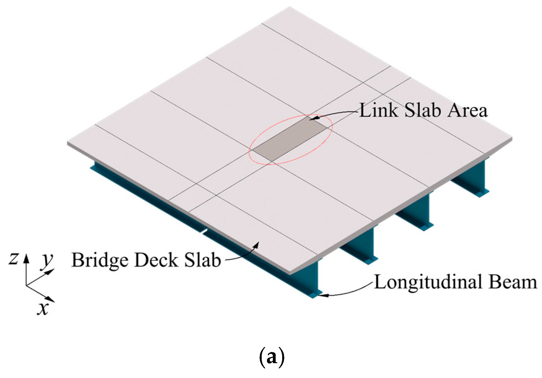
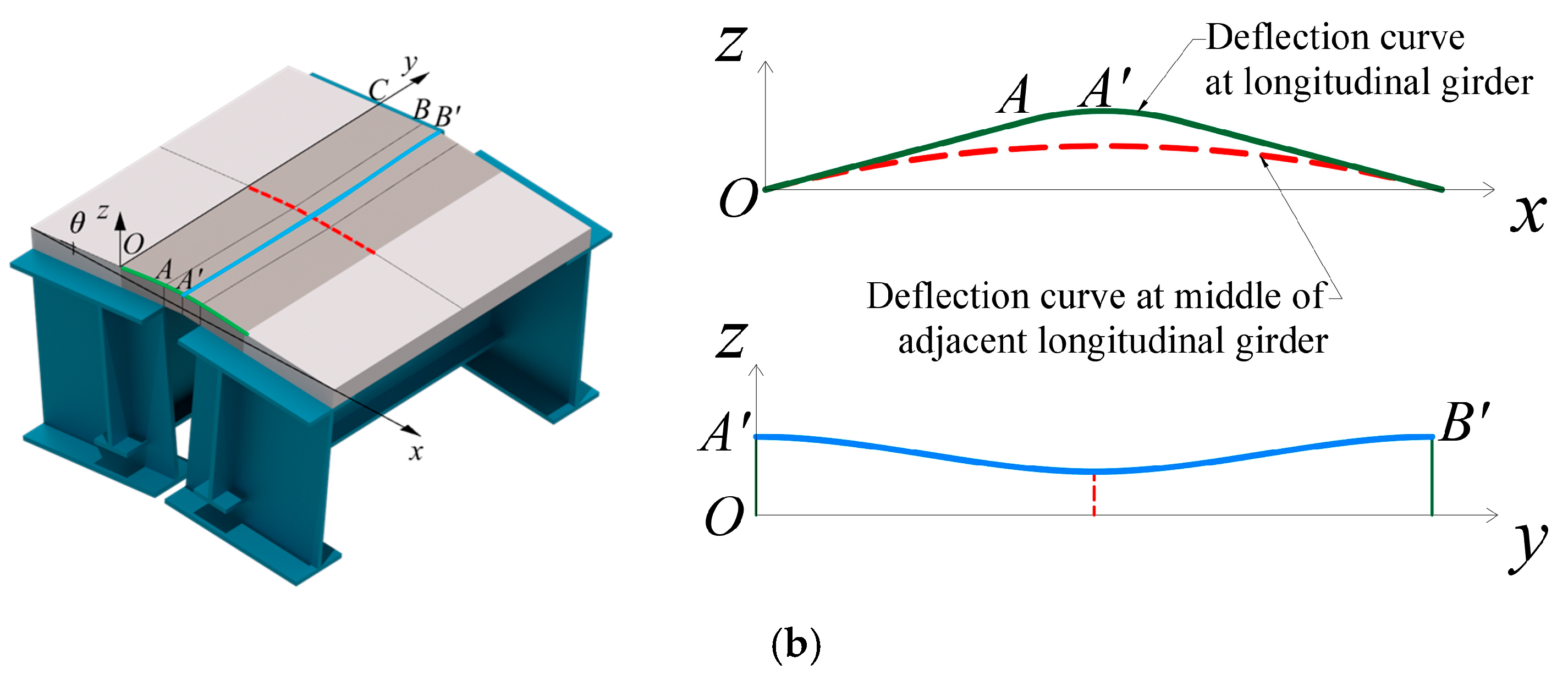
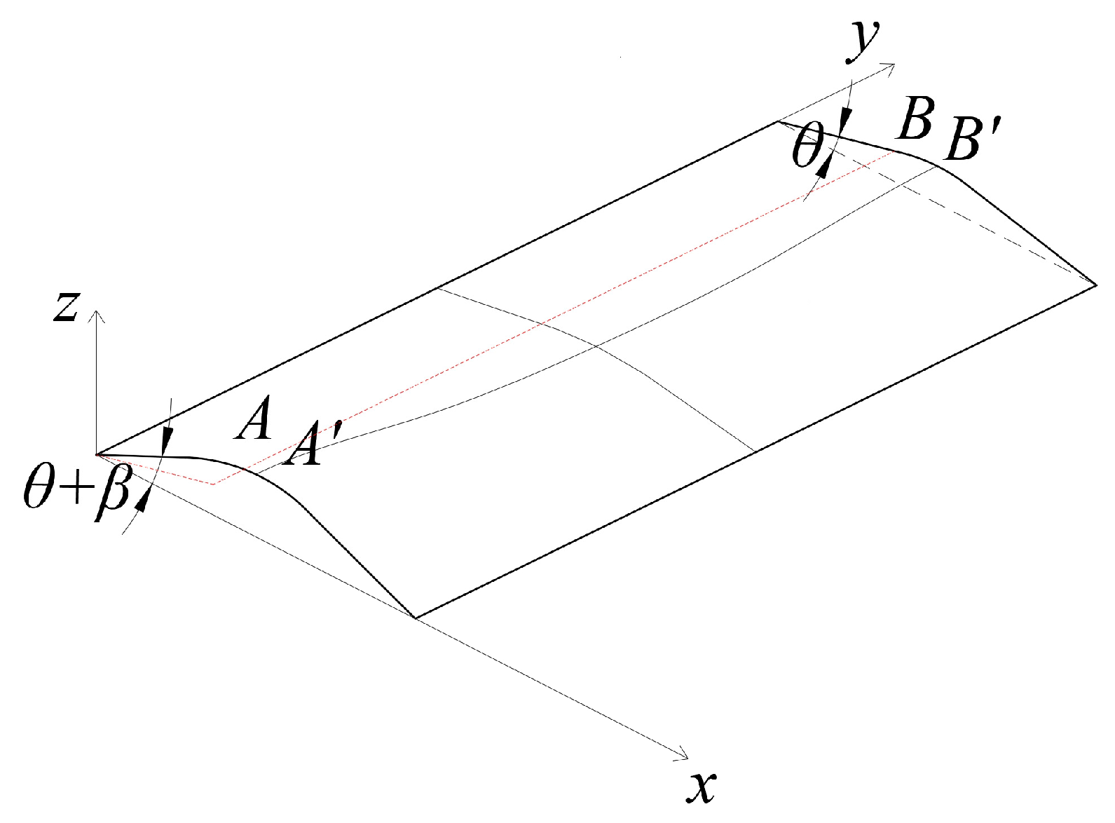
2.1. Mechanical Model of Link Slabs
- (1)
- Neglect the down deformation of the steel longitudinal girder and end crossbeam;
- (2)
- Neglect the shearing force and slip between the concrete and longitudinal girders;
- (3)
- Neglecting longitudinal displacement when the longitudinal girders rotate around the bearing.
2.2. Deflection Function of the Link Slab under Identical Steel Beam Rotation
2.3. Deflection Function of Link Slabs for Different Steel Beam Rotations
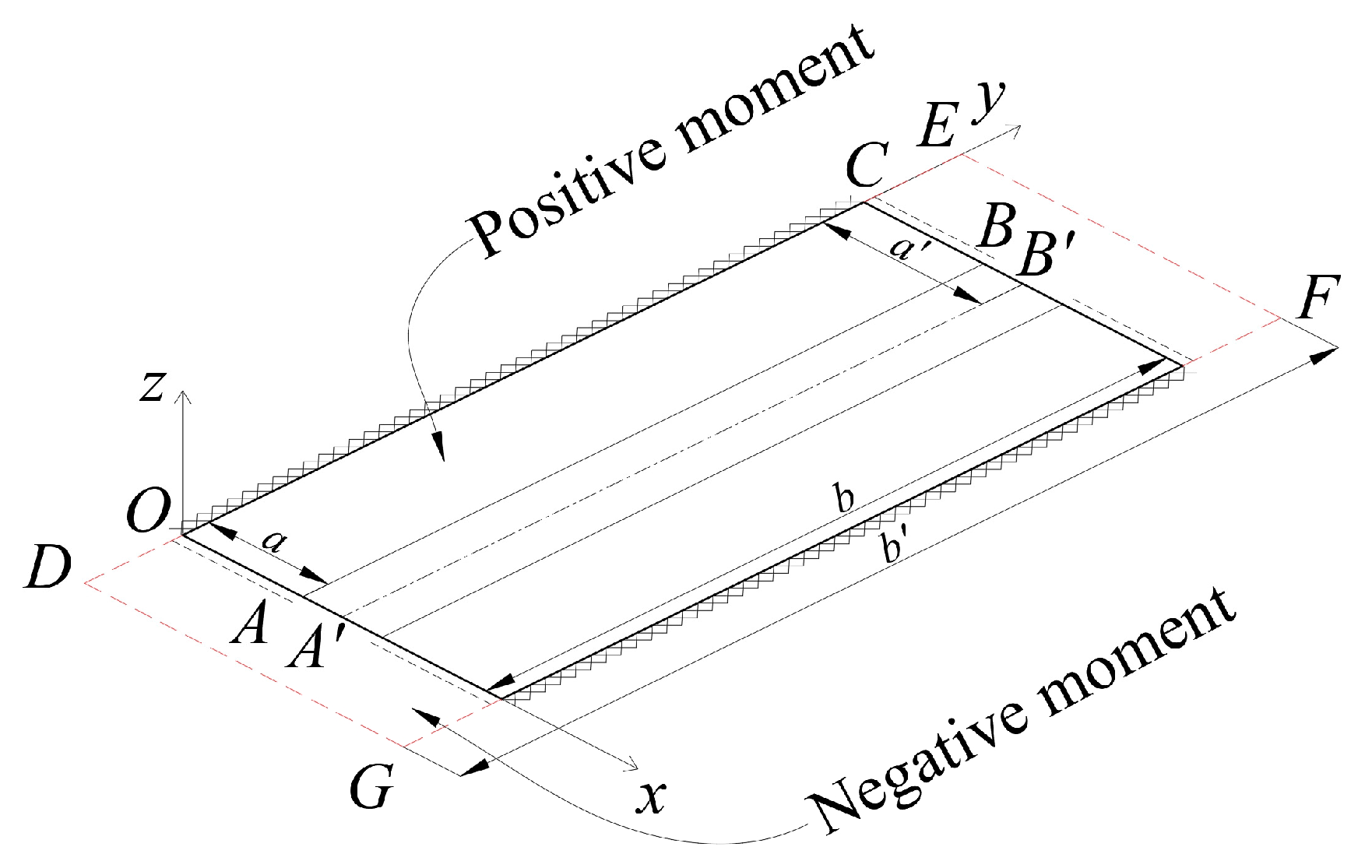
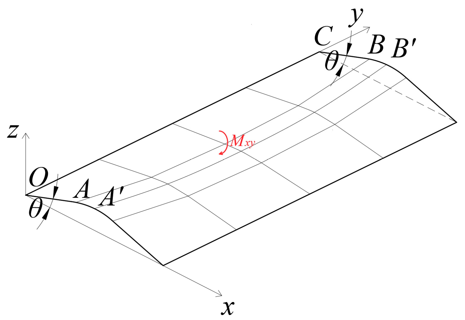
2.4. The Transverse Stress in the Negative Moment Region of the Link Slab
2.5. Longitudinal Bridge Stress of the Link Slab
3. Analysis in Engineering Applications
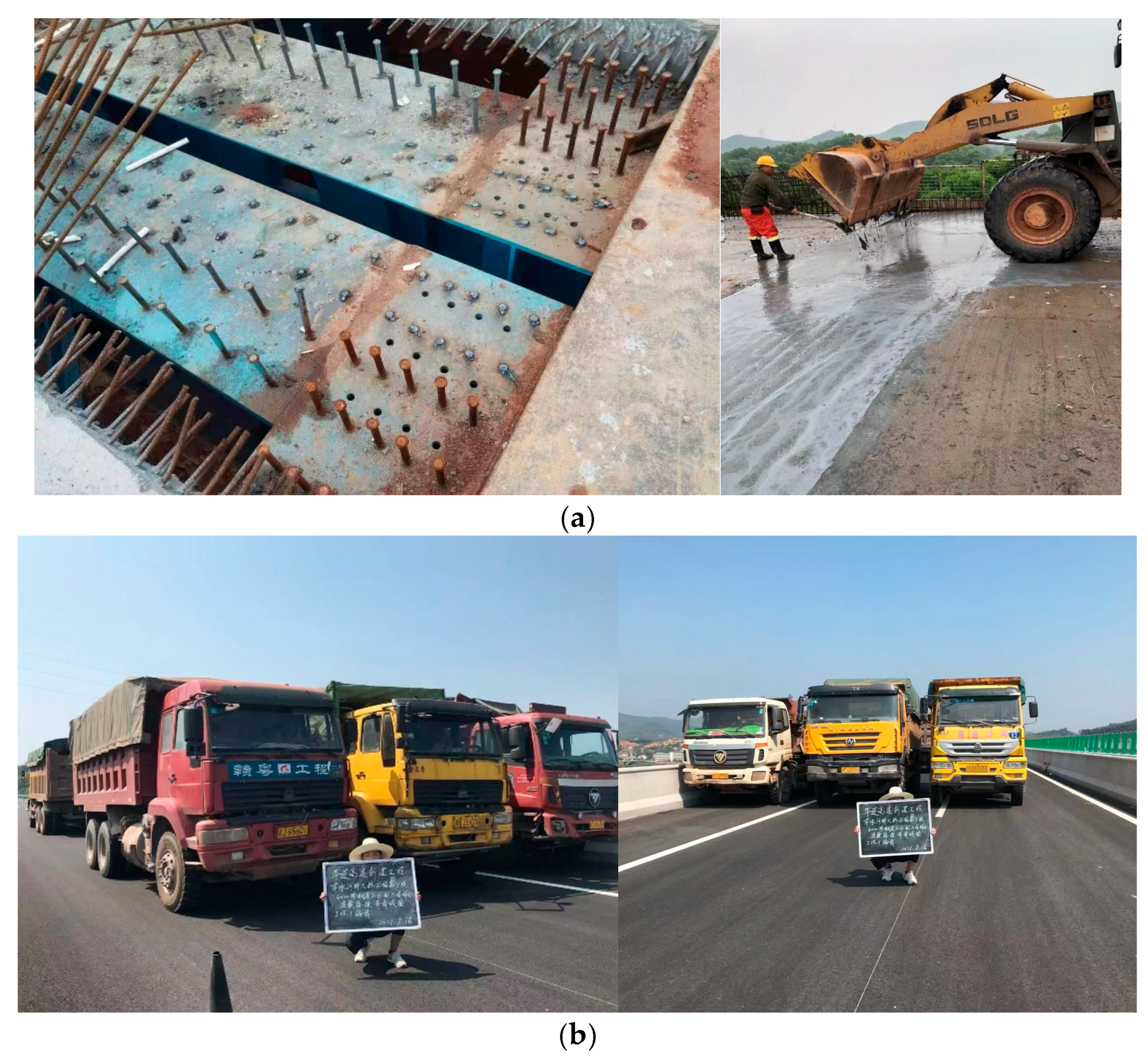
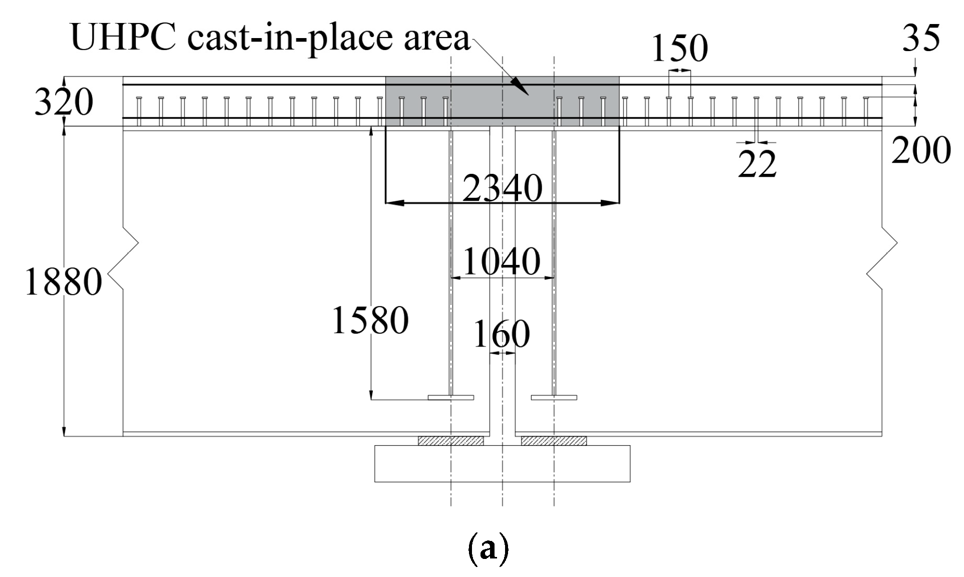
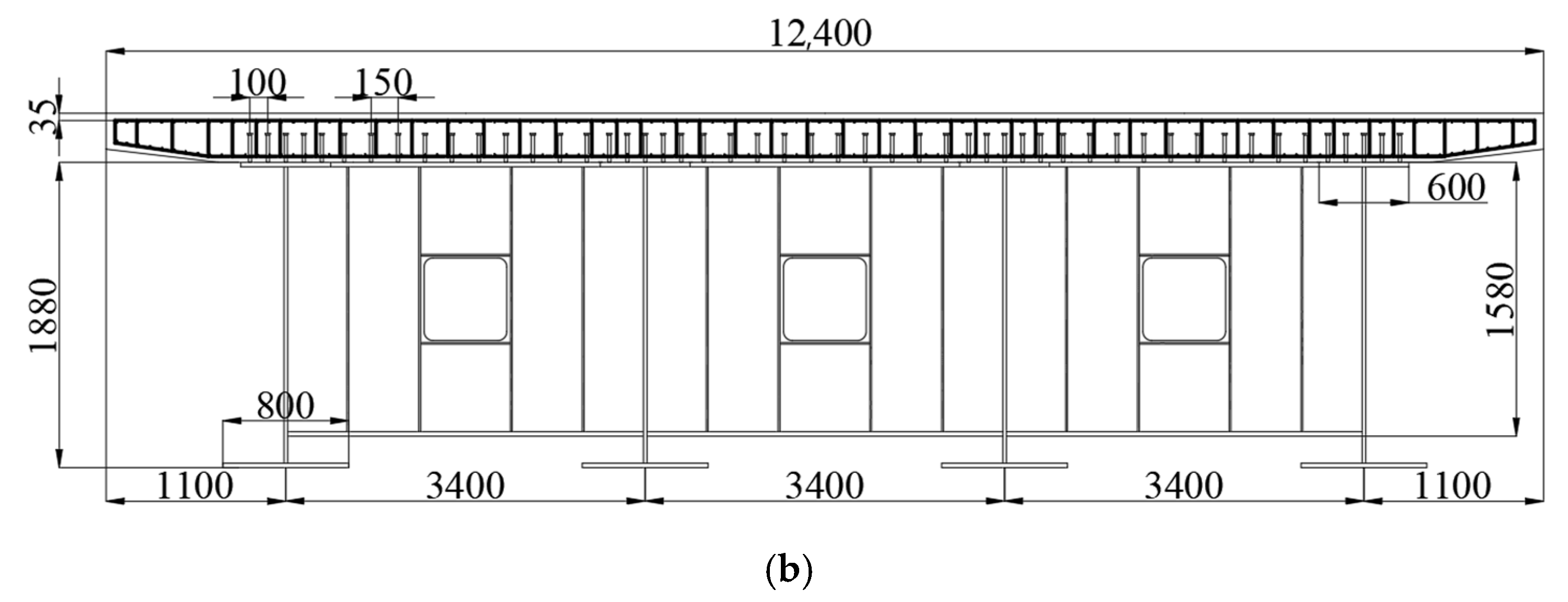
3.1. Background
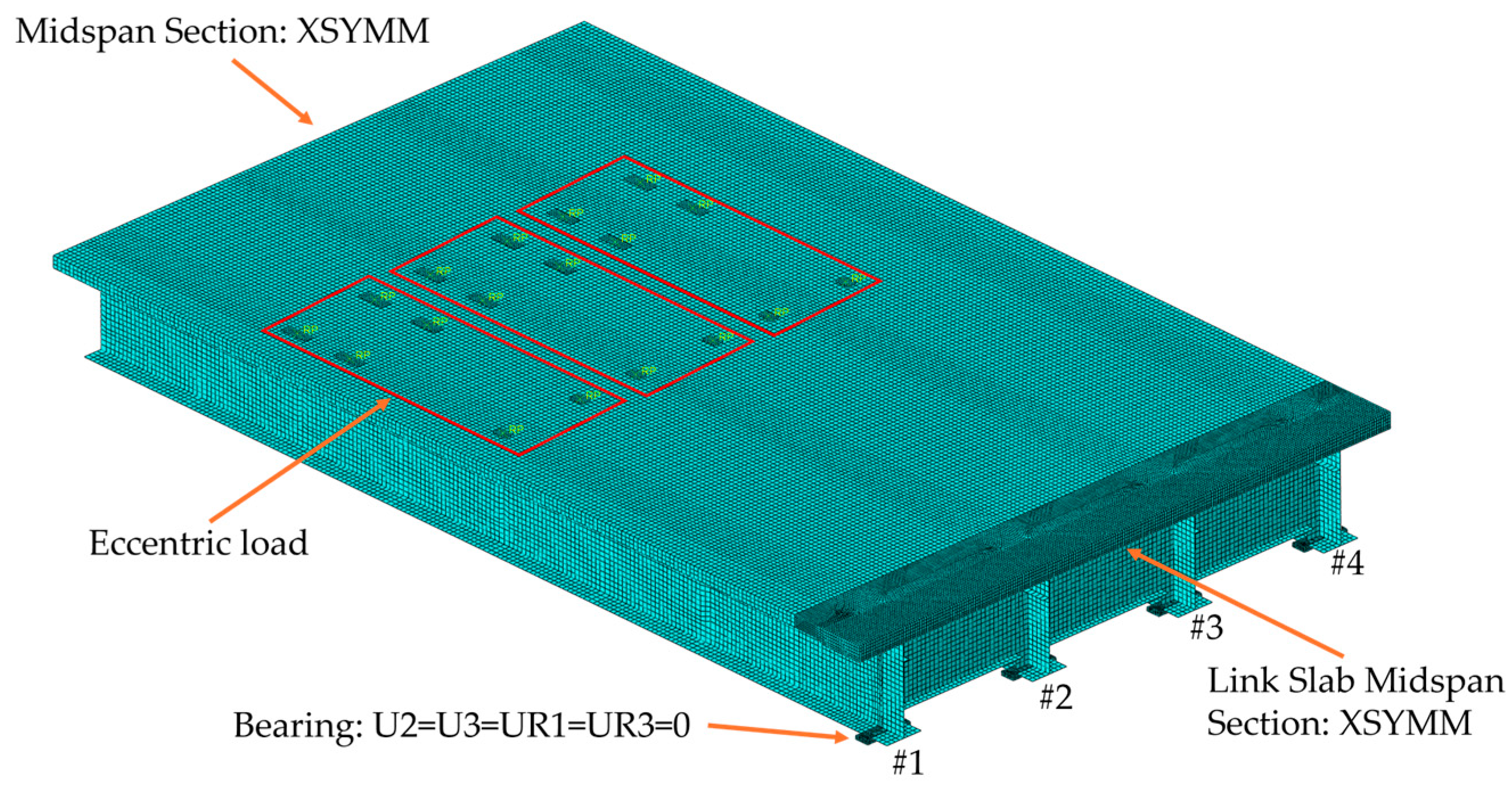
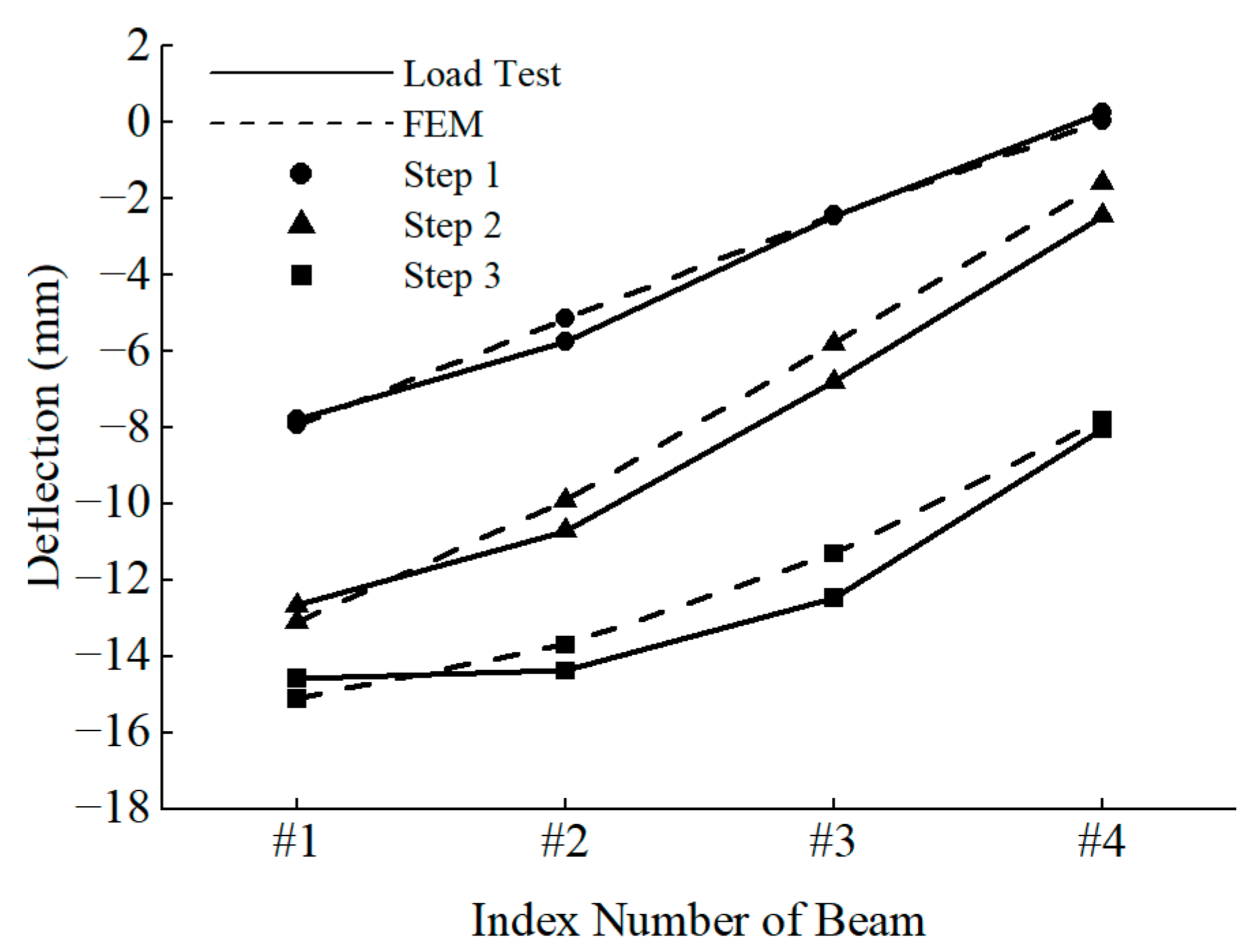
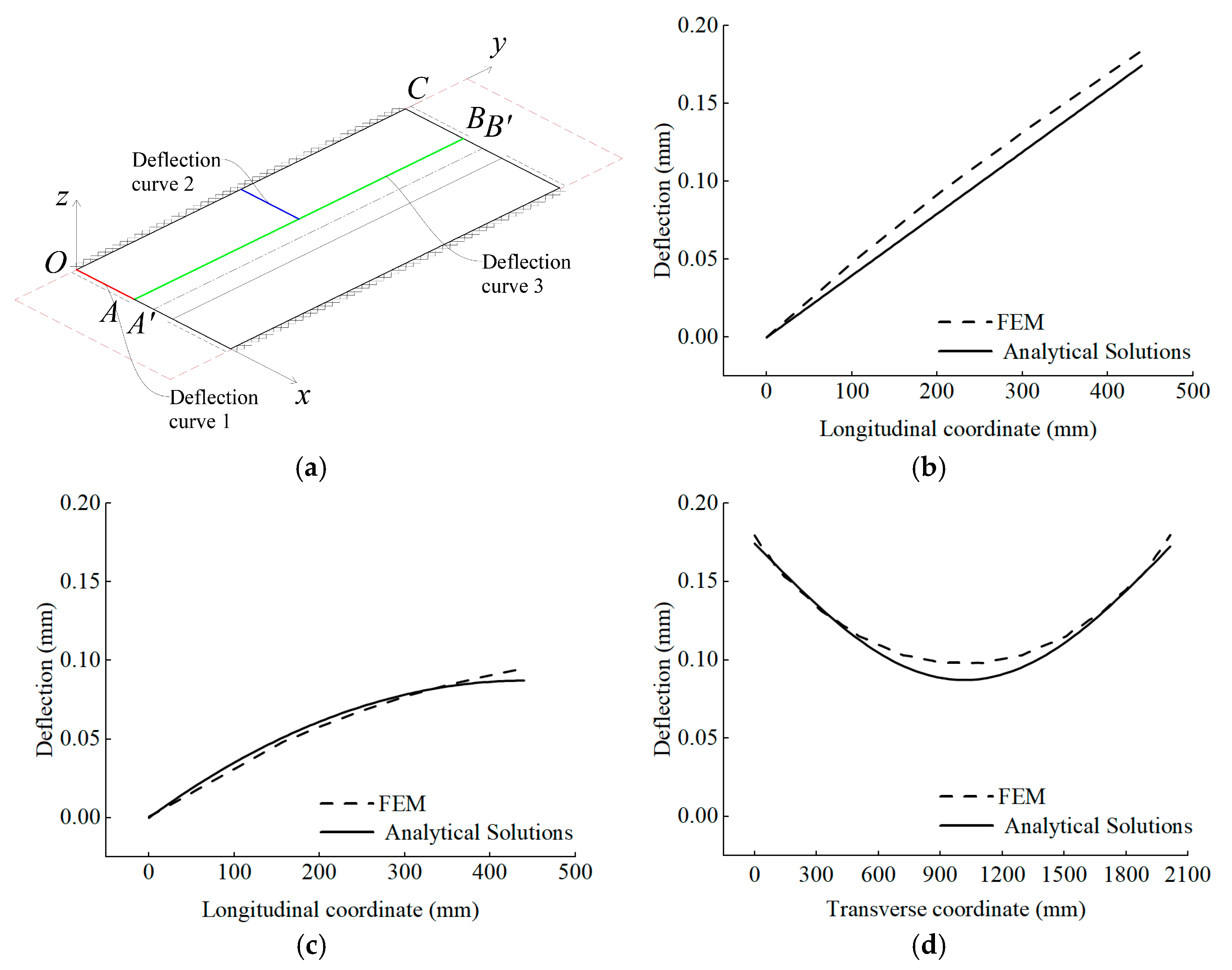
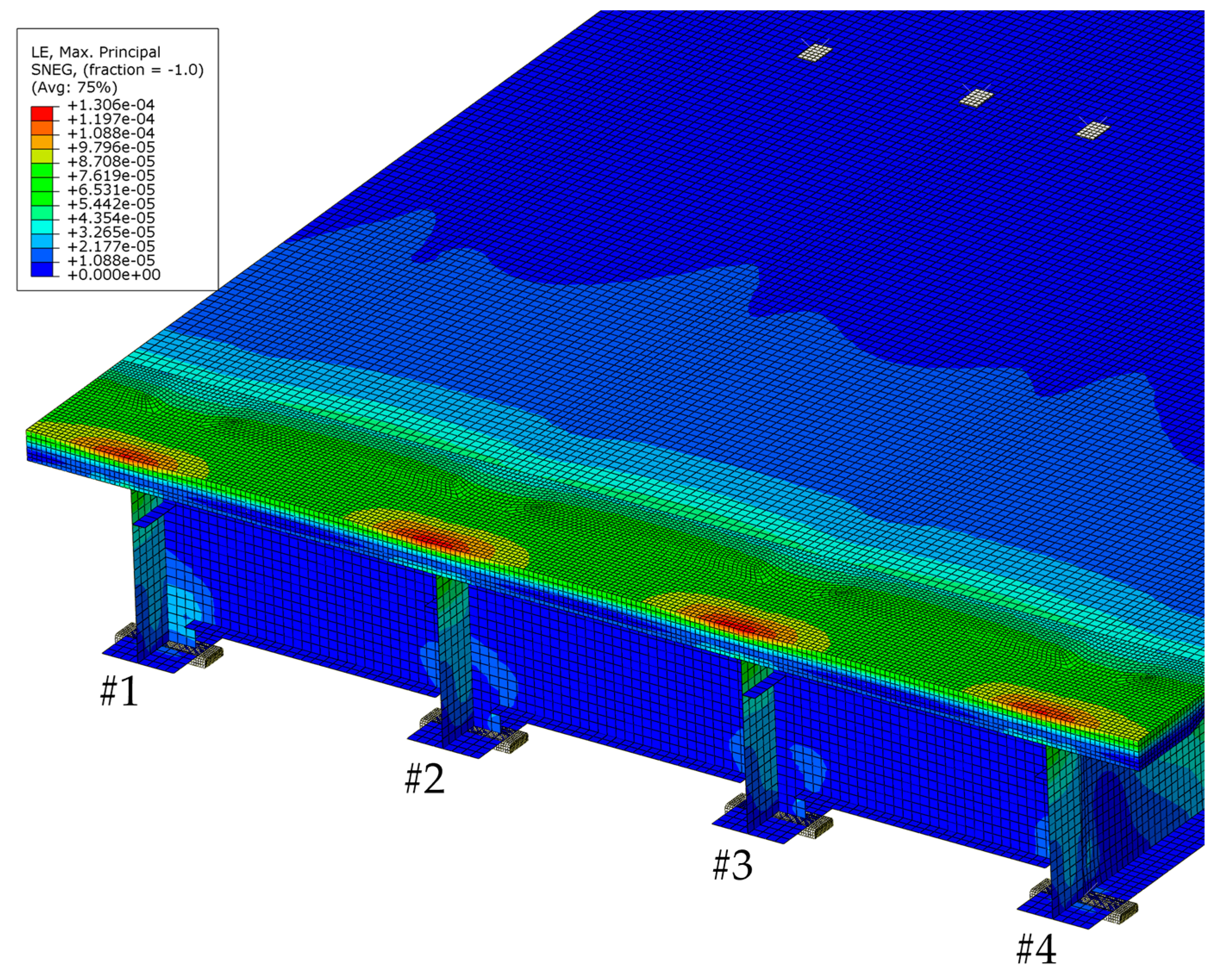
3.2. Finite Element Modeling and Verification
3.3. Results and Analysis
4. Transverse Stress of the Link Slab and Parametric Study
4.1. Transverse Stress
4.2. Parametric Study
- (1)
- Bearer to steel longitudinal girder end length a:
- (2)
- Spacing b′ of adjacent steel longitudinal girders.
- (3)
- Both a and b′ change in the same proportions.
- (4)
- Thickness δ of link slab.
5. Conclusions
- (1)
- Based on the proposed deflection and stress distribution equations for the link slab, bending due to beam end rotation induces deflection and stress not only in the longitudinal direction but also in the transverse direction. Both transverse and longitudinal peak stresses occur at the upper edges of the girder ends, which represent the most concentrated stress areas and are particularly susceptible to cracking. In the case of the bridge analyzed in this study, which utilizes UHPC link slabs, transverse stresses reached 38% of the longitudinal stresses, resulting in actual tensile stresses that were 107% of those designed based solely on longitudinal considerations.
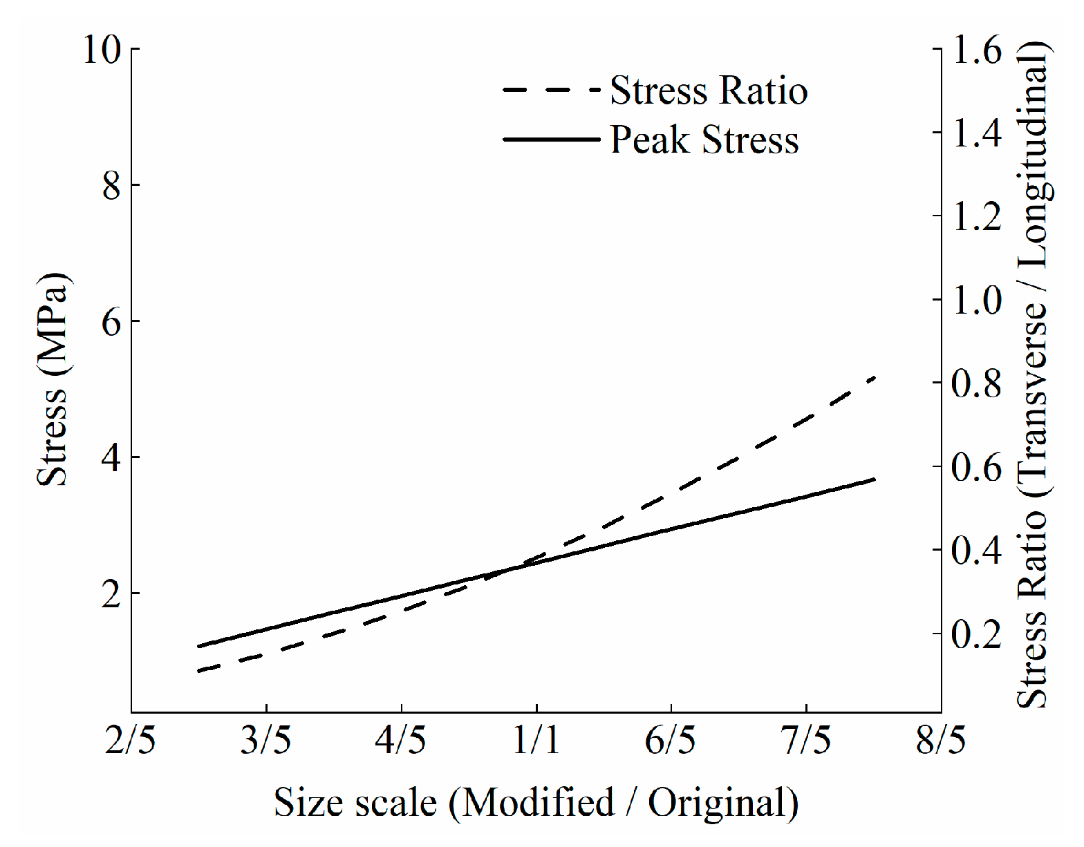
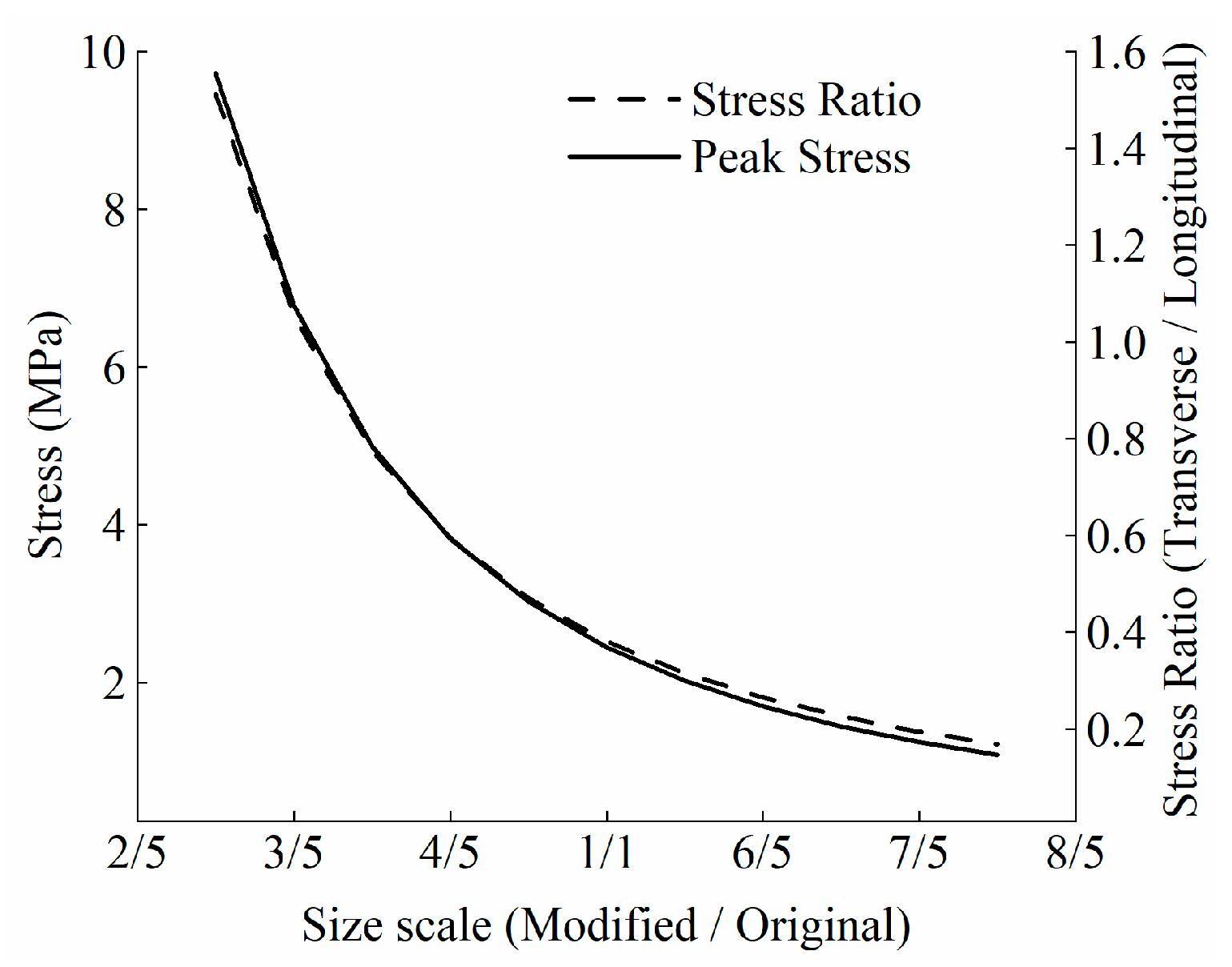
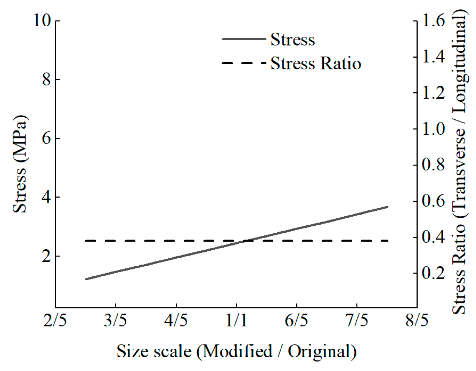
- (2)
- This study analyzed the factors influencing peak stresses using theoretical analytical solutions and identified the trends of peak transverse tensile stresses under three parameter variations. With constant beam end rotation, an increase of 50% in the distance from the bearing section to the longitudinal girder end resulted in a 50% increase in transverse stress. Additionally, reducing the transverse spacing between main girders by 40% led to transverse stress levels reaching 105% of the longitudinal stress. Furthermore, the thickness of the link slab affects both transverse and longitudinal stresses simultaneously and linearly, without altering their ratio.
- (3)
- This study also found that increasing the length of the girder ends by 50% or reducing the spacing of the longitudinal girders by 40% resulted in total stresses, considering transverse stresses, rising to 129% and 145% of the longitudinal stresses, respectively. Therefore, if only longitudinal stresses are considered as a controlling factor in the design of the link slab, the impact of transverse stresses on the overall stress analysis is significant and must be included in the evaluation.
Author Contributions
Funding
Data Availability Statement
Acknowledgments
Conflicts of Interest
References
- Bernabeu Larena, J. Evolución Tipológica y Estética de Los Puentes Mixtos En Europa. Ph.D. Thesis, E.T.S.I. Caminos, Canales y Puertos (UPM), Madrid, Spain, 2004. [Google Scholar]
- Gervásio, H.; da Silva, L.S. Comparative Life-Cycle Analysis of Steel-Concrete Composite Bridges. Struct. Infrastruct. Eng. 2008, 4, 251–269. [Google Scholar] [CrossRef]
- Ghimire, J.P.; Matsumoto, Y.; Yamaguchi, H.; Kurahashi, I. Numerical Investigation of Noise Generation and Radiation from an Existing Modular Expansion Joint between Prestressed Concrete Bridges. J. Sound Vib. 2009, 328, 129–147. [Google Scholar] [CrossRef]
- Loveall, C.L. Jointless Bridge Decks. Civ. Eng. 1985, 55, 64–67. [Google Scholar]
- Marques Lima, J.; de Brito, J. Inspection Survey of 150 Expansion Joints in Road Bridges. Eng. Struct. 2009, 31, 1077–1084. [Google Scholar] [CrossRef]
- Lepech, M.D.; Li, V.C. Application of ECC for Bridge Deck Link Slabs. Mater. Struct. 2009, 42, 1185–1195. [Google Scholar] [CrossRef]
- Hu, Z.; Shah, Y.I.; Yu, S. Cracking Analysis of Pre-Stressed Steel–Concrete Composite Girder at Negative Moment Zone. Arab. J. Sci. Eng. 2021, 46, 10771–10783. [Google Scholar] [CrossRef]
- Saber, A.; Aleti, A.R. Behavior of FRP Link Slabs in Jointless Bridge Decks. Adv. Civ. Eng. 2012, 2012, 452987. [Google Scholar] [CrossRef]
- Wolde-Tinsae, A.M.; Klinger, J.E.; White, E.J. Performance of Jointless Bridges. J. Perform. Constr. Facil. 1988, 2, 111–125. [Google Scholar] [CrossRef]
- Alampalli, S.; Yannotti, A.P. In-Service Performance of Integral Bridges and Jointless Decks. Transp. Res. Rec. 1998, 1624, 1–7. [Google Scholar] [CrossRef]
- Ulku, E.; Attanayake, U.; Aktan, H. Jointless Bridge Deck with Link Slabs: Design for Durability. Transp. Res. Rec. 2009, 2131, 68–78. [Google Scholar] [CrossRef]
- Liu, H.Y.; Zhao, S.C.; Li, L. Study on Bridge Deck Link Slabs of Simply Supported Girder Bridges. AMR 2014, 1079, 280–285. [Google Scholar] [CrossRef]
- Xue, J.; Briseghella, B.; Huang, F.; Nuti, C.; Tabatabai, H.; Chen, B. Review of Ultra-High Performance Concrete and Its Application in Bridge Engineering. Constr. Build. Mater. 2020, 260, 119844. [Google Scholar] [CrossRef]
- Graybeal, B.A. Emerging Uhpc-Based Bridge Construction and Preservation Solutions. In Proceedings of the International Symposium on Ultra-High Performance Fibre-Reinforced Concrete, Montpellier, France, 2–4 October 2017. [Google Scholar]
- Tan, L.B.; Hafezolghorani, M.; Mohamed, A.; Voo, Y.L.; Gopal, B.A.; Ghaedid, K. The First Application of Ultra-High Performance Concrete Link Slab in Malaysia. ASEAN Eng. J. 2024, 14, 209–216. [Google Scholar] [CrossRef]
- Lin, J.; Briseghella, B.; Xue, J.; Pan, X. Research on Flexural Performance and Crack Width Calculation Method of Ultra-High Performance Concrete Link Slab. Bridge Constr. 2022, 52, 60–68. [Google Scholar]
- Abdal, S.; Mansour, W.; Agwa, I.; Nasr, M.; Abadel, A.; Onuralp, Y.O.; Akeed, M.H. Application of Ultra-High-Performance Concrete in Bridge Engineering: Current Status, Limitations, Challenges, and Future Prospects. Buildings 2023, 13, 185. [Google Scholar] [CrossRef]
- Caner, A.; Zia, P. Behavior and Design of Link Slabs for Jointless Bridge Decks. PCI J. 1998, 43, 68–80. [Google Scholar] [CrossRef]
- Wing, K.M.; Kowalsky, M.J. Behavior, Analysis, and Design of an Instrumented Link Slab Bridge. J. Bridge Eng. 2005, 10, 331–344. [Google Scholar] [CrossRef]
- Au, A.; Lam, C.; Au, J.; Tharmabala, B. Eliminating Deck Joints Using Debonded Link Slabs: Research and Field Tests in Ontario. J. Bridge Eng. 2013, 18, 768–778. [Google Scholar] [CrossRef]
- Okeil, A.M.; ElSafty, A. Partial Continuity in Bridge Girders with Jointless Decks. Pract. Period. Struct. Des. Constr. 2005, 10, 229–238. [Google Scholar] [CrossRef]
- El-Safty, A.; Okeil, A.M. Extending the Service Life of Bridges Using Continuous Decks. PCI J. 2008, 53, 96–111. [Google Scholar] [CrossRef]
- Ding, Y.; Huang, Q.; Huang, J. Theoretical Analysis for Static and Dynamic Characteristics of Multi-Simple-Span Bridge with Continuous Deck. Eng. Mech. 2015, 32, 100–110. [Google Scholar] [CrossRef]
- Gergess, A.N. Analysis Of Bonded Link Slabs In Precast, Prestressed Concrete Girder Bridges. PCI J. 2019, 64, 47–65. [Google Scholar] [CrossRef]
- Gergess, A.N.; Douaihy, E.Z. Effects of Elastomeric Bearing Stiffness on the Structural Behavior of Bonded Link-Slabs. Transp. Res. Rec. 2020, 2674, 428–443. [Google Scholar] [CrossRef]
- Gergess, A.N.; Hawi, P.F. Structural Behavior of Debonded Link-Slabs in Continuous Bridge Decks. J. Bridge Eng. 2019, 24, 04019030. [Google Scholar] [CrossRef]
- Wang, C.; Shen, Y.; Zou, Y.; Zhuang, Y.; Li, T. Analysis of Mechanical Characteristics of Steel-Concrete Composite Flat Link Slab on Simply-Supported Beam Bridge. KSCE J. Civ. Eng. 2019, 23, 3571–3580. [Google Scholar] [CrossRef]
- Zhang, X.; Yan, Q.-S.; Jia, B.-Y.; Yang, Z.; Zhao, Y.-H.; Yu, X.-L. An Analytical Method for Full-Range Mechanical Behavior of Continuous Slab-Deck in Multi-Span Simply Supported Concrete Bridges. Adv. Struct. Eng. 2022, 25, 98–116. [Google Scholar] [CrossRef]
- Love, A.E.H. XVI. The Small Free Vibrations and Deformation of a Thin Elastic Shell. Phil. Trans. R. Soc. Lond. A 1888, 179, 491–546. [Google Scholar] [CrossRef]
- Tong, L.; Chen, L.; Wen, M.; Xu, C. Static Behavior of Stud Shear Connectors in High-Strength-Steel–UHPC Composite Beams. Eng. Struct. 2020, 218, 110827. [Google Scholar] [CrossRef]
- Shafieifar, M.; Farzad, M.; Azizinamini, A. Experimental and Numerical Study on Mechanical Properties of Ultra High Performance Concrete (UHPC). Constr. Build. Mater. 2017, 156, 402–411. [Google Scholar] [CrossRef]
- Fib Special Activity Group, N.M.C.; Taerwe, L.; Matthys, S. Fib Model Code for Concrete Structures 2010; Ernst & Sohn, Wiley: Hoboken, NJ, USA, 2013; ISBN 978-3-433-60409-0. [Google Scholar]
- Ansi, B. AISC 360-16, Specification for Structural Steel Buildings; Chicago AISC: Chicago, IL, USA, 2016. [Google Scholar]
- Gang, S.; Xi, Z. Study on Constitutive Model of High-Strength Structural Steel under Monotonic Loading. Eng. Mech. 2017, 34, 50–59. [Google Scholar] [CrossRef]
- Kupfer, H.; Hilsdorf, H.K.; Rusch, H. Behavior of Concrete Under Biaxial Stresses. ACI J. Proc. 1969, 66, 656–666. [Google Scholar] [CrossRef]


| C50 | UHPC120 | |
|---|---|---|
| Compressive strength fc (MPa) | 50 | 124 |
| Tensile strength ft (Mpa) | 2.64 | 9.5 |
| Ec (Gpa) (6 in, 150 mm, cube test) | 34.5 | 48.0 |
| Q235 | Q345 | |
| Es (Gpa) | 206 | 206 |
| fy (Mpa) | 235 | 345 |
| fu (Mpa) | 375 | 470 |
| HRB400 | ||
| Es (Gpa) | 200 | |
| fy (Mpa) | 400 | |
| fu (Mpa) | 540 | |
| Transverse Stress (MPa) | Longitudinal Stress (MPa) | |
|---|---|---|
| FEM | 2.67 | 6.96 |
| Proposed analytical method | 2.45 | 6.45 |
| Load test | 2.44 | 6.59 |
Disclaimer/Publisher’s Note: The statements, opinions and data contained in all publications are solely those of the individual author(s) and contributor(s) and not of MDPI and/or the editor(s). MDPI and/or the editor(s) disclaim responsibility for any injury to people or property resulting from any ideas, methods, instructions or products referred to in the content. |
© 2024 by the authors. Licensee MDPI, Basel, Switzerland. This article is an open access article distributed under the terms and conditions of the Creative Commons Attribution (CC BY) license (https://creativecommons.org/licenses/by/4.0/).
Share and Cite
Du, W.; Hu, Z.; Zhou, Z. A Method for Analyzing Transverse Stress in Link Slabs of Simply Supported Steel–Concrete Composite Bridges. Buildings 2024, 14, 3308. https://doi.org/10.3390/buildings14103308
Du W, Hu Z, Zhou Z. A Method for Analyzing Transverse Stress in Link Slabs of Simply Supported Steel–Concrete Composite Bridges. Buildings. 2024; 14(10):3308. https://doi.org/10.3390/buildings14103308
Chicago/Turabian StyleDu, Wei, Zhijian Hu, and Zhi Zhou. 2024. "A Method for Analyzing Transverse Stress in Link Slabs of Simply Supported Steel–Concrete Composite Bridges" Buildings 14, no. 10: 3308. https://doi.org/10.3390/buildings14103308
APA StyleDu, W., Hu, Z., & Zhou, Z. (2024). A Method for Analyzing Transverse Stress in Link Slabs of Simply Supported Steel–Concrete Composite Bridges. Buildings, 14(10), 3308. https://doi.org/10.3390/buildings14103308