Abstract
Compared with the traditional radiant cooling combined with a displacement ventilation air conditioning system, an air conditioning system of radiant cooling combined with an attached jet can not only effectively prevent dew on the surface of the radiant cooling plate, but also further improve the cooling capacity of the radiant air conditioning system; however, most scholars have installed the radiant cooling plate on the radiant roof and the ground, and there are fewer studies on installing the radiant cooling plate on the two sides of the wall. Based on this, this paper builds an experimental system of radiant air conditioning and conducts experiments on summer working conditions in June–October to experimentally study the indoor thermal and humid environments and thermal comfort under different water supply temperatures when radiant cold panels are installed in single-side-wall, symmetrical-wall, and top-panel positions. The experimental results show that the optimal water supply temperatures of single-side-wall radiation combined with an attached-jet air conditioning system, symmetrical-wall radiation combined with an attached-jet air conditioning system, and roof radiation combined with an attached-jet air conditioning system are 18 °C, 22 °C, and 16 °C, respectively, and at the same time, the temperatures of the human body’s working area under the above water supply temperatures are 26 °C, 26.3 °C, and 26.4 °C, respectively. The average humidities in the working area are 58%, 53%, and 57%, which can meet the requirements of our country’s level II comfort when the indoor heat and humidity environment is stable, the energy consumption amounts of the radiant end are 5.71 kW·h, 3.99 kW·h, and 10.81 kW·h, respectively, and the highest efficiency of cooling and dehumidification is achieved with the symmetric-wall radiation combined with the adherent-jet air conditioning system.
1. Introduction
In the early 1920s, China’s building energy consumption accounted for more than 10% of the total energy consumption of the country, which was about 6% higher than the global average [1]. As global energy consumption continues to rise, the share of building energy consumption in total energy consumption is also increasing, causing environmental problems such as air, water, and soil pollution, as well as energy waste, increasing carbon emissions, and exacerbating the harsh changes in the global climate. Currently, China’s building life cycle energy consumption accounts for up to 46.5% of national energy consumption. In addition, people are demanding more and more comfort in buildings, leading to a significant increase in the share of energy consumption of air conditioning systems in building energy consumption [2]. In China, air conditioning energy consumption accounts for a large proportion of building energy consumption, accounting for 40–50% [3] of the total energy consumption. In order to achieve the national goal of “carbon neutrality and carbon peaking” and to promote sustainable development, it is essential to reduce the energy consumption of air conditioning systems.
Radiant air conditioning can use a cooling source of 14–20 °C for cooling and a heat source of 30–40 °C for heating, and it is suitable for low-grade energy sources, such as solar, geothermal, hydroelectric, and wind, which can greatly reduce the energy consumption of buildings. According to the data, radiant air conditioning can reduce building energy consumption by 28% to 40% [4], which has obvious energy-saving advantages compared with traditional air conditioning.
Causone et al. [5,6] found that, when coupling a radiant air conditioning system with a ventilation system, the air was made to flow close to the radiant cold plate, which not only prevented condensation, but also enhanced the strength of the convective heat transfer of the radiant cold plate. Mustakallio et al. [7] found that a radiant air conditioning system combining radiant roof panels and hybrid ventilation could create a uniform thermal environment for the room, regardless of how the distribution of heat sources in the room changed, with a wide range of applications. Luther et al. [8] studied the energy efficiency ratio of lightweight radiant air conditioning systems and found that lightweight radiant air conditioners were 40% more energy efficient than regular air conditioners.
Tang Feixiao [9] used CFD simulation to study the effect of the low-temperature air supply angle on the thermal comfort of radiantly cooled rooms and obtained the air supply angle at the highest level of indoor comfort. Zhou Xuanyu et al. [10,11] used CFD simulation to analyze the indoor thermal and humid environments of indoor cold radiant surfaces under the ventilation modes of an advective jet and displacement ventilation, and found that the air supply mode of the advective jet could effectively reduce the risk of condensation on cold radiant surfaces, the blowing sensation caused by the indoor airflow rate was lower, and the comfort level was relatively high under the ventilation condition of the advective jet. Jin Wufeng et al. [12,13,14,15] found that the total cooling capacity of a radiant air conditioner with an attached jet air supply was about 9.6% higher than that of a radiant air conditioner with a displacement ventilation air supply, but the radiant heat transfer ratio was much lower than that of a radiant refrigeration air conditioner with displacement ventilation; meanwhile, under the same conditions, radiant cooling panels with an attached jet air supply had lower dew point temperatures, and the indoor temperatures were also lower. Wu Xiaozhou et al. [16] used a combination of subjective questionnaires and experimental tests to explore the effects of human thermal sensation, localized thermal sensation, and skin surface temperature under two types of air conditioning with floor air supply and mixed air supply combined with radiant roof panels.
Zhang Zebin et al. [17,18] simulated composite air conditioning with radiant cooling coupled with jet adsorption and found that the same-side upward-feeding and downward-returning air supply was more suitable for the radiant cooling of the top plate, and Wu Haodong et al. [19] simulated a composite air conditioning system with jet adsorption and a radiant cold plate and found that the side-wall radiant cold plate was arranged in the direction of the directional air supply outlet and in the lower part of the wall adjacent to the wall where the air supply outlet was located, which could reduce the asymmetric radiant temperature of the room by 1.5 °C to 2 °C and effectively prevent dew condensation on the side-wall radiant cold plate. It was found that arranging the side-wall radiant cooling panels in the lower space of the wall adjacent to the wall where the air supply outlet was located could reduce the asymmetric radiant temperature of the room by 1.5 °C to 2 °C and effectively prevent the side-wall radiant cooling panels from dewing. Zhang Han [20] investigated the cooling conditions of the combination of a kick air supply, floor air supply, and different radiant surfaces through experiments and simulations, and the results showed that the indoor heat and humidity environment were the best under the combination of a kick air supply and radiant cooling on the top surface. Xiao Rongfang et al. [21] studied the effect of indoor shading on the indoor heat and humidity environment under the cooling conditions of the radiant ceiling, and found that the main effects of the presence or absence of internal shading and different internal shading materials were the heat exchange efficiency between the radiant ceiling panels and the indoor air, and the temperature of the indoor air after the stabilization of the indoor heat and humidity environment.
Most of the radiant air conditioning systems studied by scholars lay the radiant cold plate on the roof and floor position, and most of the air supply methods used are displacement ventilation, based on which this study builds a radiant air conditioning system experimental bench; installs the radiant cold plate on the symmetrical vertical wall, single vertical wall, and roof in three positions; and explores the changes in indoor temperature and humidity and comfort under the condition of a 12–22 °C water supply temperature, and at the same time, the comfort rate and the energy consumption are measured in terms of the combination of a subjective questionnaire and an experimental test. At the same time, the optimal working condition is selected in terms of the comfort rate and the energy consumption of the radiant end, which provides a reference for the actual project.
2. Experimental Methods
2.1. Test Laboratories and Test Systems
The laboratory is located in the radiation air conditioning laboratory suite on the fourth floor of the science and technology building of Shandong Jianzhu University; the L × W × H of the suite is 5.9 m × 4 m × 2.9 m, with a total floor area of 23.6 m2. The north side of this experimental suite is an ordinary brick wall with a plastered surface, the north wall and the corridor are adjacent to each other, and the south wall and the east wall are all partition sandwich panels with a thickness of 100 mm, which have a good thermal insulation effect, as shown in Figure 1c.
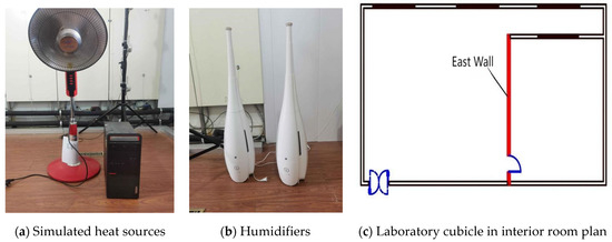
Figure 1.
Simulated heat sources and humidifiers.
The indoor simulation heat source is provided with the heating device, and the indoor heat source is about 90 W/m2. The use of a humidifier simulates the dispersion of humidity by the human body, approximately 400 g/h, as shown in Figure 1.
This experimental system consists of the top-plate radiation cooling system and the attached jet air supply, in which the areas of the single-side-wall, symmetrical-wall, and top-plate radiation cold plate laying are 8.75 m2, 17.5 m2, and 12.5 m2, respectively; the attached jet air outlet is a 2000 × 10 mm claw air outlet, and the corresponding physical diagram of the system is shown in Figure 2, Figure 3 and Figure 4; the distribution of wall measuring points is shown in Figure 5.
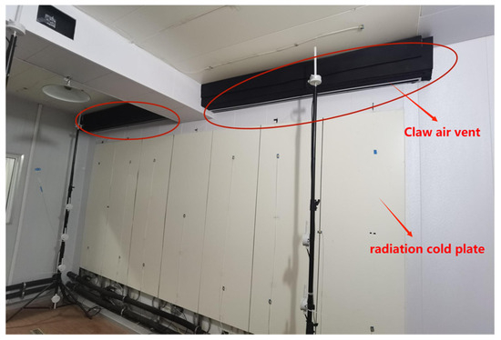
Figure 2.
Physical diagram of single-side-wall radiant combined with adherent-jet air conditioning system.

Figure 3.
Physical diagram of symmetric-wall radiation combined with adherent-jet air conditioning system.

Figure 4.
Physical diagram of the radiant roof combined with adherent-jet air conditioning system.
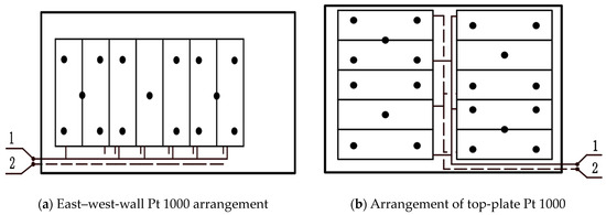
Figure 5.
Distribution of wall side points. 1—Water supply, 2—Return water.
A radiation-cold-plate cooling system uses an air-cooled heat pump as a cold source, the unit for York’s air-cooled chilled water (heat pump) unit, the nominal refrigeration capacity of 11.2 KW, and heating capacity of 12.5 KW; the radiation-cold-plate end of the water temperature using the air-cooled unit directly controls, that is, in the air-cooled unit control panel, to set the temperature; due to the use of chiller units with a fixed-frequency compressor, and the unit’s refrigeration capacity is much larger than the demand for cold water, the system involves setting up a buffer tank as a buffer of cold water, and this buffer tank selection is for the 100 L buffer insulation tank. A radiation-cold-plate cooling system is divided into two groups of circulation, one of which is the circulation between the unit and the buffer tank, and the unit internal pump supplies circulation; the other group of circulation between the buffer tank and the end of the circulation uses a head of 17 m, and the flow rate of a 5 m3/h fixed-frequency pump, due to the buffer tank being higher than the height of the end of the buffer tank; the return pipe is installed in the buffer tank at the end of the side of the lower interface, so the pump needs to be installed in the end of the return pipe. Installation is in the return pipe at the end to provide kinetic energy for the return water. When determining the water supply temperature in this experiment, the average water supply temperature during the experiment is used as the determined value of the water supply temperature, and the difference between the average temperature and the determined temperature is within ±0.5 °C. A schematic diagram of the radiant-cold-plate water system is shown in Figure 6.
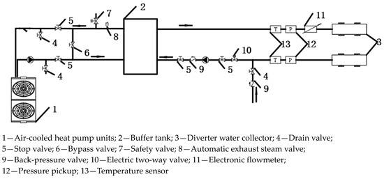
Figure 6.
Schematic diagram of radiant-cold-plate water system.
The adhering jet air supply system uses a duct machine and a combined air conditioner (shown in Figure 7) to process the fresh air together, in which the duct machine cools and dehumidifies the fresh air, and the combined air conditioner warms, humidifies, and pressurizes the wind processed using the duct machine. The nominal cooling capacity of the duct machine is 5.1 KW, the heating capacity is 6.2 KW, and the circulating air volume is 750 m3/h. Since the duct machine adopts refrigerant cooling, the cooling and dehumidifying effect of the duct machine is better and the temperature of the fresh air processed using the duct machine can be directly controlled through the panel; the heating capacity of the combined air conditioner is 10 KW, the humidifying capacity is 8 kg/h, and the air volume is 1000 m3/h. The heating section of the combined air conditioner consists of three parts of heating strips, and the number of heating strips can be adjusted according to the air temperature of the group; the air supply adopts a variable-frequency fan, so the frequency of the variable-frequency fan can be adjusted directly to control the size of the air supply.

Figure 7.
Schematic diagram of air system.
2.2. Test Parameters and Measurement Point Layout
The principle of the experimental measurement point arrangement refers to the “Radiant Heating and Cooling Technical Regulations” [22], and the specific arrangement is as follows: the indoor temperature and humidity probes in the vertical direction are located 0.1 m, 0.7 m, 1.1 m, and 1.5 m from the ground, and 0.1 m from the roof (shown in Figure 8). In the horizontal direction, according to the five-point method, five measurement points are arranged at the same horizontal height (shown in Figure 9).

Figure 8.
Space probe height arrangement.
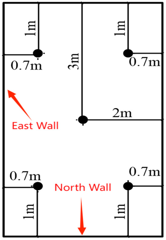
Figure 9.
Plan view of the space probe.
The test instruments and tests used in this experiment are shown in Table 1.

Table 1.
Experimental test apparatus.
2.3. Experimental Design Parameters
The experimental site is located in Jinan City, according to the “Design Code for Heating, Ventilation and Air Conditioning of Civil Buildings” [23]; the minimum fresh air volume of this laboratory design is 120 m3/h, but because of the attenuation effect of adsorption jet air supply, the fresh air volume of 120 m3/h cannot achieve the effect of good adsorption jets, so the design of the fresh air volume is 320 m3/h, to ensure that the surface of the radiant cold plate furthest away from the air outlet can achieve the effect of adhering to the jet, and at the same time, the temperature of the air supply was set to 26 °C (relative humidity of 50%).
The experimental site is located in Jinan City, and Jinan is located at latitude 36°40′ north and longitude 117°00′ east. And Jinan summer air conditioning indoor and outdoor calculation parameters are shown in Table 2 below.

Table 2.
Calculated indoor and outdoor parameters for summer air conditioning in Jinan.
The indoor design parameters and comfort levels of the experimental air conditioning system are shown in Table 3 and Table 4.

Table 3.
Indoor design parameters for air conditioning of areas where people stay for long periods of time.

Table 4.
PMV and PPD values corresponding to different thermal comfort levels.
In this paper, the indoor design temperature is 26 °C, the design humidity is 55%, and the thermal comfort design level is Class II thermal comfort; the water supply flow rate is a constant flow operation of 0.77 m3/h.
3. Experimental Results and Data Analysis
The length of each experiment is 11 h, recording data every minute, taking the data within the first 10 hours for the analysis, and doing the same experiment three times for each working condition system. Based on the experimental pattern, the available data are finally selected by checking one by one and eliminating the anomalies.
3.1. Single-Side-Wall Radiation Combined with Attached-Jet Air Conditioning System
3.1.1. Room Temperature
As shown in Figure 10, the indoor air temperatures of the single-side-wall radiation combined with an adherent-jet air conditioning system are 24.6 °C, 25 °C, 25.8 °C, 26 °C, 26.3 °C, 26.7 °C, and 26.7 °C in order when the final indoor temperatures at a height of 0.7 m (the center of the human body sitting and standing) reach stabilization under the condition of the water supply temperature ranging from 12 °C to 22 °C, and at a height of 1.1 m (the center of the human body standing). The final indoor temperatures at a 1.1 m height (center of human body standing) are 24.9 °C, 25.4 °C, 26 °C, 26.2 °C, 26.5 °C, and 27.1 °C in order when the final indoor temperatures reach stabilization.

Figure 10.
Temperature changes at different heights in the room with different water supply temperatures.
At the same water supply temperature, the change in indoor temperature in the working area of the human body is relatively small, so the temperature in the working area at the horizontal height of the room created by the one-sided-wall radiation combined with the adhering-jet air conditioning system is relatively stable.
3.1.2. Indoor Humidity
In the single-side-wall radiation combined with the adherent-jet air conditioning system, at a water supply temperature of 12 °C, the dew-point temperature of the air on the surface of the radiant cold plate is reached because the surface temperature of the radiant cold plate is too low, and thus condensation appears on the surface of the radiant cold plate (as shown with the markings in Figure 11), and obvious droplets of water are formed.
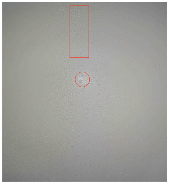
Figure 11.
Radiation-cold-plate surface condensation. Diameter of condensation droplets is between 1 mm and 9 mm.
As shown in Figure 12, the relative humidity at the height of 0.7 m is 62%, 60%, 59%, 58%, 56%, and 54%, respectively, and at the height of 1.1 m, it is 59%, 58%, 56%, 55%, 54%, and 51%, respectively, under the condition of the water supply temperature ranging from 12 °C to 22 °C. The relative humidity at the height of 0.7 m is 59%, 58%, 56%, 55%, 54%, and 51%, respectively. The relative humidity of the indoor air is the highest at the height of 0.7 m. The relative humidity gradually decreases at the heights of 0.1 m, 1.1 m, 1.5 m, and 2.8 m. Since the attached jet air supply of the single-side-wall radiation combined with the attached-jet air conditioning system flows along the sequence of “radiant cold plate—floor—wall”, the drier air is directly delivered to the bottom of the room. The dry air is directly sent to the bottom of the room, and because the wind speed of the one-sided-wall-attached jet is relatively fast, the heat and humidity exchange of the air at the bottom of the space will be strengthened, and therefore a higher relative humidity is formed at 0.7 m. The relative humidity at 0.7 m is higher than that at the bottom of the room.

Figure 12.
Relative humidity at different heights in the room with different water supply temperatures.
3.1.3. Human Comfort PMV−PPD
As shown in Figure 13 and Figure 14, under the condition of a water supply temperature of 12 °C to 22 °C, from the vertical direction, the PMV at 0.7 m from the radiant cold plate is between 0 and 0.68, and the PPD is between 5% and 15%; the PMV at 2 m from the radiant cold plate is between 0.07 and 0.74, and the PPD is between 5% and 17%; and the PMV at 3.3 m from the radiant cold plate is between 0.13 and 0.81 and the PPD is between 5% and 19%. Horizontally, the PMV at a height of 0.7 m from the floor is between 0.1 and 0.74, and the PPD is between 5% and 17%; the PMV at a height of 1.1 m from the floor is between 0.16 and 0.88, and the PPD is between 6% and 22%. The human comfort PMV−PPD rises with the increase in water supply temperature, and at the same water supply temperature, the farther away from the radiant cold plate, the larger the PMV and PPD values, which is mainly due to the attenuation effect of radiation intensity; the farther away from the source of radiation, the lower the intensity of the radiation received; and the higher the air temperature, the larger the PMV and PPD, at the same water supply temperature. Under the same water supply temperature, the PMV and PPD at the height of 0.7 m are smaller than those at the height of 1.1 m. This is mainly due to the fact that the height of 0.7 m to 2.4 m belongs to the jet reflux area formed with the advected jet [24], which is relatively well handled using the hot and humid environment, but the settling effect of the cooler air leads to the emergence of this trend.

Figure 13.
PMV−PPD values for different vertical surface positions at different water supply temperatures.
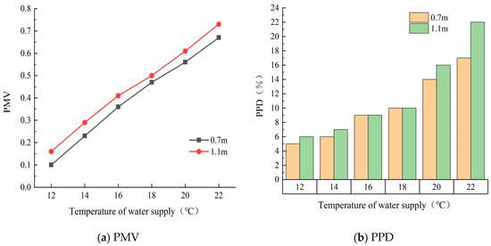
Figure 14.
PMV−PPD values for different horizontal heights at different water supply temperatures.
The PMV−PPD of the single-side-wall surface radiation combined with the adherent-jet air conditioning system under the condition of a water supply temperature from 12 °C to 22 °C meets the comfort standard of Class II when it is running stably [25] and the PMV−PPD under the condition of a water supply temperature from 12 °C to 18 °C meets the comfort standard of Class I in all cases. In terms of comfort, a lower water supply temperature should be selected for the single-side-wall radiant combined with the adherent-jet air conditioning system, while the personnel position should be as close as possible to the radiant cooling panels.
3.2. Symmetrical-Wall Radiation Combined with Attached-Jet Air Conditioning System
3.2.1. Indoor Temperature
As shown in Figure 15, the indoor air temperatures of the symmetrical-wall radiation combined with the adherent-jet air conditioning system are 23.5 °C, 24.4 °C, 24.7 °C, 25.1 °C, 25.7 °C, and 26.3 °C in order when the final indoor temperatures at the height of 0.7 m stabilized under the water supply temperatures range from 12 °C to 22 °C, and the final indoor temperatures at the height of 1.1 m stabilized with the minimum temperatures are 23.4 °C, 24.3 °C, 24.6 °C, 25 °C, 25.6 °C, and 26.2 °C. At the same water supply temperature, the indoor temperature change in the human body working area is relatively small, so the temperature in the working area at the horizontal height of the room created by the symmetrical-wall radiation combined with the adherent-jet air conditioning system is relatively stable. Regarding symmetrical-wall radiation combined with the attached-jet air conditioning system at a height of 1.1 m, the temperature is less than the temperature at a height of 0.7 m, mainly due to the symmetrical vertical walls of the room being covered with the radiation cold plate, and the room on both sides of the vertical walls is attached to the jet, and the room will form a confluence of the “air lake”, thus leading to the temperature at a height of 1.1 m being less than the 0.7 m temperature.
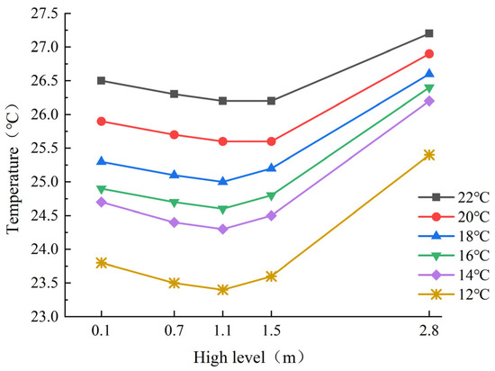
Figure 15.
Temperature changes at different heights in the room with different water supply temperatures.
3.2.2. Indoor Humidity
Regarding symmetrical-wall radiation combined with the adherent-jet air conditioning system at the water supply temperature of 12 °C, the symmetrical-wall surfaces displayed a condensation phenomenon (shown in Figure 16), but did not form obvious water droplets.

Figure 16.
Radiation-cold-plate surface condensation. Diameter of condensation droplets is between 1 mm and 3 mm.
As shown in Figure 17, under the condition of a water supply temperature from 12 °C to 22 °C, the relative humidity at the height of 0.7 m is 65%, 63%, 61%, 58%, 56%, and 53%, respectively, and the relative humidity at the height of 1.1 m is the same as that at the height of 0.7 m, and it is the maximum value of the indoor air humidity monitoring point. In the working area, the humidity distribution of indoor air is relatively uniform, and the lowest point of indoor relative humidity occurs near the top plate, i.e., in the upper area of indoor air, which is due to the symmetrical vertical wall’s adhering jet air supply flowing along the sequence of “radiant cold plate—floor—air”, and the adhering jets on both sides will transport the relatively dry air directly to the bottom of the room, and the air will be transported to the bottom of the room. Dry air is directly transported to the bottom of the room, so the relative humidity of the air at the bottom of the room is low, while the symmetrical vertical wall of the adhering jet is formed using the “air lake” of the convergence of the formation of a certain height of the upward airflow, the convergence of the formation of the upward airflow will enhance the flow of air indoors, the convergence of the airflow at the relatively high speed will enhance the heat and humidity exchange of air within a certain height, and the airflow will be enhanced. The air velocity at the confluence is relatively fast, which will strengthen the heat and humidity exchange of the air within a certain height and the sinking of cold air and wet air; thus, the relative humidity at the height of 0.7 m, 1.1 m, and 1.5 m is higher, and that near the top plate is relatively lower.

Figure 17.
Relative humidity at different heights in the room with different water supply temperatures.
3.2.3. Human Comfort PMV−PPD
As shown in Figure 18 and Figure 19, under the condition of a water supply temperature of 12 °C to 22 °C, from the vertical direction, the PMV at a 0.7 m height from the east radiant cold plate is between −0.49 and 0.39, and the PPD is between 5% and 10%; the PMV at a 2 m height from the east radiant cold plate is between −0.48 and 0.42, and the PPD is between 5% and 10%. Horizontally, the PMV at a height of 0.7 m from the floor is between −0.48 and 0.42, with PPD between 5% and 10%, and at a height of 1.1 m from the floor, the PMV is between −0.41 and 0.42, with PPD between 5 and 9%. The human thermal sensation PMV rises with the water supply temperature, and the farther away from the radiant cold plate at the same water supply temperature, the greater the PMV; the predicted percentage of dissatisfaction PPD varies relatively little and is relatively stable when the water supply temperature is between 12 °C and 22 °C.
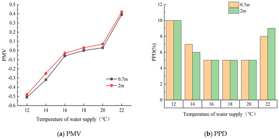
Figure 18.
PMV−PPD values for different vertical surface positions at different water supply temperatures.

Figure 19.
PMV−PPD values for different horizontal heights at different water supply temperatures.
This is mainly due to the fact that the total cooling capacity of the one-sided-wall radiation combined with the adherent-jet air conditioning system is relatively large, and when the low-temperature water is utilized for radiant cooling, this trend is mainly due to the relatively large total cooling capacity of the unilateral-wall radiant combined with the adherent-jet air conditioning system, which is slightly cooler in the case of thermal sensation of the human body when using low-temperature water for radiant cooling, and slightly warmer at high-temperature water for cooling. When the symmetrical-wall radiation combined with the adherent-jet air conditioning system operates stably, its PMV−PPD not only meets our Class II comfort standard, but also meets the Class I comfort standard. In terms of comfort, the water supply temperature of 12~22 °C can be used as the water supply temperature for radiant cooling, but the comfort level of the room under the condition of a water supply temperature of 16~20 °C is higher, and at the same time, the comfort level of the indoor personnel placement in the area close to or far away from the radiant cold plate does not have a big difference, and personnel can be placed in the same area.
3.3. Roof Radiant Combined with Attached-Jet Air Conditioning System
3.3.1. Room Temperature
As shown in Figure 20, the indoor air temperatures of the roof radiation combined with the adherent-jet air conditioning system are 25.4 °C, 26 °C, 26.4 °C, 26.8 °C, 27 °C, 27.6 °C, 27.6 °C, and 27.6 °C in order when the final indoor temperatures at the height of 0.7 m are stabilized under the water supply temperatures ranging from 12 °C to 22 °C, and the final indoor temperatures at the height of 1.1 m are 25.2 °C, 25.9 °C, 26.3 °C, 26.6 °C, 26.9 °C, and 27.5 °C when the final indoor temperatures reached stability. The temperatures are 25.2 °C, 25.9 °C, 26.3 °C, 26.6 °C, 26.9 °C, and 27.5 °C in that order. At the same water supply temperature, the change in indoor temperature in the human body working area is relatively small, so the temperature in the working area at the horizontal height of the room created by the radiant ceiling combined with the adherent-jet air conditioning system is relatively stable.
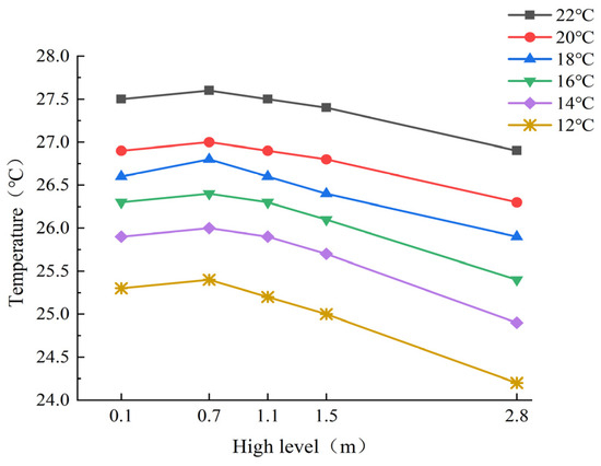
Figure 20.
Temperature changes at different heights in the room with different water supply temperatures.
3.3.2. Indoor Humidity
Regarding the roof radiation combined with the adherent-jet air conditioning system at the water supply temperature of 12 °C, the roof radiation surface involves a dew phenomenon (shown in Figure 21), the dew phenomenon compared to the first two radiation air conditioning systems is more serious, and there is an emergence of a large area of obvious water droplets.

Figure 21.
Radiation-cold-plate surface condensation. Diameter of condensation droplets is between 1 mm and 7 mm.
As shown in Figure 22, under the condition of a water supply temperature from 12 °C to 22 °C, the relative humidity at the height of 0.7 m is 63%, 59%, 57%, 53%, 50%, and 46%, respectively, and the relative humidity at the height of 1.1 m is the same as that at the height of 0.7 m. The relative humidity of the indoor air was highest at the indoor monitoring point at a height of 2.8 m. The relative humidity was the same and lowest at indoor heights of 0.1 m, 0.7 m, and 1.1 m. At different water supply temperatures; the indoor height of the monitoring point of the relative humidity difference is relatively low; the maximum is only 3%; the indoor wet environment is relatively uniform, due to the top plate attached to the jet air mainly along the “roof—wall—floor” order of flow; and jet reflux will form a certain height of the “air lake”. The height of the “air lake” area and the airflow velocity in this area are relatively low [15], and part of the dry air travels to the bottom of the room, but the relatively large humidity of the air can be settled in the bottom of the room, so the relative humidity of the air in the indoor working area is less or the same; the radiant roof due to the air velocity of the attached jet air supply is relatively high, so the radiant roof is relatively homogeneous. It is relatively high so that the heat and humidity exchange near the radiant top plate is more intense, and thus the relative humidity of the air at the top of the room is higher.

Figure 22.
Relative humidity at different heights in the room with different water supply temperatures.
3.3.3. Human Comfort PMV−PPD
As shown in Figure 23 and Figure 24, under the condition of a water supply temperature of 12 °C to 22 °C, from the vertical direction, the PMV at 0.7 m from the air outlet of the adherent jet is between 0 and 0.53, and the PPD is between 5% and 12%; the PMV at 2 m from the air outlet of the adherent jet is between 0.03 and 0.55, and the PPD is between 5% and 12%, respectively; and the PMV at 3.3 m from the air outlet of the adherent jet is between 0.07 and 0.58, and the PPD is between 5% and 13%. The PMV at 3.3 m from the air outlet ranged from 0.07 to 0.58, and the PPD ranged from 5% to 13%. Horizontally, the PMV at a height of 0.7 m from the floor ranged from 0.07 to 0.84, and the PPD ranged from 5% to 20%; the PMV at a height of 1.1 m from the floor ranged from 0.1 to 0.84, and the PPD ranged from 5% to 20%.
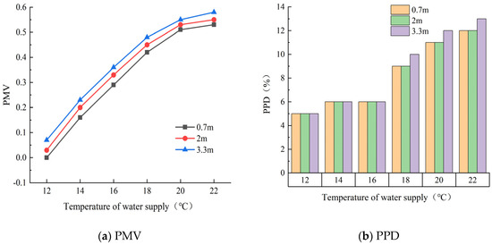
Figure 23.
PMV−PPD values for different vertical surface positions at different water supply temperatures.
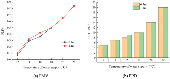
Figure 24.
PMV−PPD values for different horizontal heights at different water supply temperatures.
The human comfort PMV−PPD rises with the rise in water supply temperature, and the farther away from the top-plate adhering jet outlet under the same water supply temperature, the greater the value of PMV and PPD, and the farther away from the top-plate adhering jet outlet, the smaller the adhering jet wind speed, the smaller the convective heat exchange, and the higher the air temperature near its radiant cold plate, and there is a weakening of the sinking effect of the cold air. The cold air sinking effect being weakened results in higher air temperatures, which lead to greater PMV and PPD at the far end of the air outlet from the top-plate adherent jet.
The PMV−PPD of the top-plate radiant combined with the adsorbed-jet air conditioning system meets China’s Class II comfort standard when the operation is stable, and the PMV−PPD meets the Class I comfort standard under the condition that the water supply temperature is 12~18 °C. Considering from the aspect of comfort, the water supply temperature of the roof radiation combined with the adhering-jet air conditioning system should be chosen as a lower water supply temperature, and at the same time, the personnel position should be as close as possible to the lower part of the adhering jet air outlet.
3.4. Comparative Evaluation of Working Conditions
3.4.1. Measurement Error
The direct measurement errors obtained from the measurement ranges of each device according to Table 1 are shown in Table 5 below.

Table 5.
Direct measurement error.
3.4.2. Heat Transfer
As can be seen from Figure 25, the maximum calculated radiant heat transfer is 36 W/m2, 35.4 W/m2, and 38 W/m2 for the single-side-wall radiation combined with the adherent-jet air conditioning system, symmetrical-wall radiation combined with the adherent-jet air conditioning system, and the roof radiation combined with the adherent-jet air conditioning system, respectively, under the conditions of a water supply flow rate of 0.77 m3/h and air supply volume of 320 m3/h, and the minimal calculated radiant heat transfer is 17.6 W/m2, 10.1 W/m2, and 18.6 W/m2, respectively; the lower the water supply temperature, the greater the difference between the convective heat transfer and the radiative heat transfer of the same air conditioning system. The larger the difference, on the one hand, the lower the water supply temperature, and the lower the temperature of the radiant-cold-plate surface; the size of the radiative heat transfer depends on the average temperature of the radiant-cold-plate surface and the average temperature of the non-cooled surface, the radiation surface temperature decreases, the non-cooled surface’s average temperature decreases, and the average temperature change of the radiant-cold-plate surface is greater than the average temperature of the non-cooled-plate surface, but the radiation constant of the surface of the blackbody exists, so that the radiative heat transfer varies in a relatively small manner. On the other hand, the air supply mode of the air conditioning system is the adherent jet, the convective heat transfer mode is the forced convective heat transfer, and its heat transfer coefficient is mainly affected by the cold-surface temperature of the radiant plate, the velocity of the adherent jet air speed, and the influence of the supply air temperature. However, due to the constant air supply temperature and advection jet air velocity in this experiment, the convective heat transfer is mainly affected by the surface temperature of the radiant cold plate, whose temperature mainly affects the kinematic viscosity of the advection jet air, and thus the convective heat transfer varies a lot, which makes the convective heat transfer have a large difference with the radiant heat transfer.

Figure 25.
Heat exchange of different air conditioning systems at different water supply temperatures.
Under the same water supply temperature, the convective heat transfer and radiative heat transfer per unit area of the top-plate radiation combined with the attached-jet air conditioning system are the largest, and the convective heat transfer and radiative heat transfer per unit area of the symmetric-wall radiation combined with the attached-jet air conditioning system are the smallest, in which the area of the radiative cold plate of the symmetric-wall radiation combined with the attached-jet air conditioning system is twice as large as that of the radiant cold plate of the unilateral-wall radiation combined with the attached-jet air conditioning system, but the ratio of radiative heat transfer does not differ twice. On the one hand, the water supply flow rate of the two air conditioning systems is the same, and the radiant cold plate is limited using the water supply temperature, and the surface temperature of the radiant cold plate does not differ much; on the other hand, the area of the radiant cold plate of the symmetric-wall radiation combined with the adherent-jet air conditioning system is larger, and in the case of the same external factors, the weighted temperature of the non-cooled surface is lower, and the radiant heat transfer of the symmetric-wall radiation combined with the adherent-jet air conditioning system is the smallest. The amount of radiant heat transfer in a symmetrical-wall radiant combined with the adhered-jet air conditioning system is lower than that in a single-side-wall radiant-cooling air conditioning system, and thus the percentage of radiant heat transfer does not differ by a factor of two. Symmetrical-wall radiation combined with the attached-jet air conditioning system’s convective heat transfer is less than the single-side-wall radiation combined with the attached-jet air conditioning system—mainly involving two air conditioning system’s air supply and water supply temperatures under the same conditions; symmetrical-wall radiation combined with the attached-jet air conditioning system’s jet air velocity is less than the single side of the wall-radiation refrigeration air conditioning system, and the attached-jet air conditioning system involves the convective heat transfer mode for forced convection heat transfer. The higher the wind speed, the stronger the convective heat transfer capacity, so the symmetrical-wall radiation combined with the adhering-jet air conditioning system’s convective heat transfer is less than a single side of the wall radiation combined with the adhering-jet air conditioning system’s convective heat transfer.
Top-plate radiation combined with the attached-jet air conditioning system’s radiant heat transfer and convective heat transfer is greater than the other two air conditioning systems, on the one hand, because of the air supply method for the attached jet, and unilateral jet, in the case of the same amount of air supply, the jet wind speed is relatively large, and forced convective heat transfer is relatively strong, and on the other hand, because of the air near the surface of the radiant top plate and the radiant roof plate of the air after the exchange of heat; the air temperature is lowered, the density of the air becomes larger, the cold air sinks, the radiant top surface of the air near the surface of the air temperature rises, the forced convective heat transfer enhances the top radiation combined with the attached-jet air conditioning system’s radiation, and convective heat transfer is the largest.
3.4.3. Cooling and Dehumidifying Efficiency
According to three kinds of radiation air conditioning systems with the room height of 0.7 m and 1.1 m that are seen at the ambient temperature, the indoor heat and humidity environment, after stabilization of the air temperature, difference is not large, so in the analysis of air-conditioning-system cooling and dehumidification efficiency, an analysis of a height can be undertaken, and this section selects the 0.7 m height of the room temperature to be analyzed.
As can be seen from Figure 26 and Figure 27, the indoor temperature of symmetrical-wall radiation combined with the adherent-jet air conditioning system decreases the fastest; on the one hand, the radiant cold plate is installed on both sides of the vertical wall, and the unit area of the radiant cold plate has a larger heat exchange area with the indoor heat sources such as office equipment and the human body in the working area, and the heat exchange efficiency is high; on the other hand, the symmetrical-wall-radiation air conditioning of the radiant cold plate has the largest spreading area, and the total heat exchange is the largest. On the other hand, the symmetrical-wall-radiation air conditioner has the largest area of the radiant cold plate and the largest total heat exchange, so the indoor temperature under its air conditioning system drops the fastest. At 0.7 m from the center of the human body sitting and standing, when the water supply temperature is 12~14 °C, the cooling capacity of top-plate radiation combined with the attached-jet air conditioning system is larger than that of single-side-wall radiation combined with the attached-jet air conditioning system, and when the water supply temperature is 16~22 °C, the cooling capacity of top-plate radiation combined with the attached-jet air conditioning system is smaller than that of single-side-wall radiation combined with the attached-jet air conditioning system, and when the radiant cold plate is installed on the top plate, there is a difference between the rising hot air and the radiant cold plate. When the radiation cold plate is installed in the top plate, there is hot air rising and radiation cold plate contact, but when the water supply temperature is relatively high, the radiation cold plate on the top of the room and the rising hot air convection heat transfer intensity is relatively low, the air temperature after heat transfer is relatively high, and the rate of precipitation is relatively slow, but in the low-temperature water supply and cooling, the convection heat transfer intensity becomes larger, and the rate of precipitation of the cold air accelerates, so regarding the top plate of the radiant combined with the attachment of the jet stream air conditioning system in the low-temperature water supply, the cooling capacity is greater than the single-side-wall radiation combined with the attachment of the jet stream air conditioning system. Therefore, the cooling capacity of the top-plate radiation combined with the attached-jet air conditioning system in the low-temperature water supply is larger than that of the single-side-wall radiation combined with the attached-jet air conditioning system, and the cooling capacity in the high-temperature water supply is smaller than that of the single-side-wall radiation combined with the attached-jet air conditioning system.

Figure 26.
Temperature changes in different air conditioning systems for the first 60 min of operation at different water supply temperatures.

Figure 27.
Cooling capacity of different air conditioning systems for 60 min before running at different water supply temperatures.
According to the relative humidity of three types of radiant air conditioning systems in the indoor environment at a height of 0.7 m and 1.1 m, it can be seen that there is not much difference in the relative humidity of the air in the indoor thermal and humid environments after they are stabilized, so when analyzing the dehumidification efficiency of the air conditioning system, it is sufficient to analyze a height. In this section, the humidity at a height of 0.7 m is selected for the analysis. In the experiment, when the amount of air supply and air supply temperature and humidity remain unchanged, the same kind of air conditioning system with different water supply temperatures has basically the same dehumidification efficiency, and at the same room temperature of the indoor air humidity, it is more obvious; the size of its size reaction is for the size of the relative air humidity, so it should be possible to select the indoor temperature for the water supply temperature conditions similar to the water supply temperature conditions, respectively, and the water supply temperature of 18 °C of the single side of the wall surface of the radiation combined with the adhering jet was selected. The air conditioning system with a water supply temperature of 18 °C, the air conditioning system with a symmetrical-wall radiation combined with an attached jet at a water supply temperature of 22 °C, and the air conditioning system with a roof radiation combined with an attached jet at a water supply temperature of 16 °C were selected for a comparative analysis.
As can be seen from Figure 28, after 1 h of operation of the air conditioning system, the humidity content of the air under the unilateral wall radiation combined with the adherent-jet air conditioning system, the symmetrical-wall radiation combined with the adherent-jet air conditioning system, and the top-plate radiation combined with the adherent-jet air conditioning system is 11.83 g/kg, 11.21 g/kg, and 12.13 g/kg, respectively, of which the symmetrical-wall radiation combined with the adherent-jet air conditioning system has the lowest relative humidity in the room. The relative humidity in the room is the lowest under the symmetrical-wall radiation combined with the attached-jet air conditioning system, where the attached jet air supply system is on both sides of the wall, and the dry air supply is in direct contact with the high-humidity air in the room, which has a larger contact area and a better dehumidifying effect, and thus the lowest relative humidity in the room is under the symmetrical-wall-radiation air conditioning system; the highest relative humidity in the room is found in the ceiling radiation combined with the attached-jet air conditioning system, which is located at the top of the room, and the air is not exposed to a high temperature and high humidity due to the rise in the high-temperature and high-humidity air. Since it takes time for the high-temperature and high-humidity air to rise and come into contact with the dry air supply from the top, and it also takes time for the cold air to sink, the highest RH is found in the roof radiation combined with the attached-jet air conditioning system.

Figure 28.
Humidity changes in the different air conditioning systems.
In summary: For the main purpose of cooling and dehumidification of a room, it is recommended to use symmetrical-wall radiation combined with an attached-jet air conditioning system; for the distance between the walls of the room, it is recommended to use the roof radiation combined with an attached-jet air conditioning system.
3.4.4. Analysis of Energy Consumption at Radiant Ends
Radiant-end energy consumption includes not only the energy consumed by exchanging with the indoor heat source (referred to as heat exchange in this paper), but also the energy transferred from the capillary tubes of the radiant cold panels to the outdoors through the enclosure structure.
The energy consumption of the radiant-cold-plate air conditioning system can be seen in Figure 29. The energy consumption of the radiant end rises sharply in the hour before the air conditioning system is turned on, and this stage is the main stage of indoor cooling. Under the condition of a water supply temperature from 12 °C to 22 °C, the energy consumption of the radiant end of the unilateral wall radiation combined with the adherent-jet air conditioning system is 11.07 kW·h, 8.84 kW·h, 7.44 kW·h, 5.71 kW·h, 4.21 kW·h, and 2.86 kW·h in order during the operation of the air conditioning system for 10 h, and the energy consumption of the radiant end of the symmetrical-wall radiation combined with the adherent-jet air conditioning system is 16.46 kW·h, 14.09 kW·h, 11.65 kW·h, 9.2 kW·h, 6.89 kW·h, and 3.99 kW·h in that order, and the energy consumption of the radiant end of the symmetrical-wall radiation combined with the adherent-jet air conditioning system is 15.86 kW·h, 14.24 kW·h, 10.81 kW·h, and 8.73 kW·h in that order, as well as 6.75 kW·h and 5.58 kW·h.
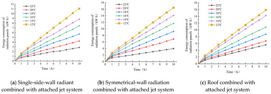
Figure 29.
Radiant-end energy consumption of different air conditioning systems at different water supply temperatures.
At the same water supply temperature, the energy consumption of the radiant end of the symmetrical-wall radiation combined with the attached-jet air conditioning system is the largest, and that of the radiant end of the one-sided-wall radiation combined with the attached-jet air conditioning system is the smallest; however, after that, in the air conditioning system’s operation time, at the water supply temperature of 22 °C, the energy consumption of the radiant end is the largest for the top-plate radiation combined with the attached-jet air conditioning system, which is the largest. When the water supply temperature is 12~20 °C, the maximum energy consumption at the end of radiation is symmetric-wall radiation combined with the attached-jet air conditioning system; at this time, the heat transfer per unit area of the top-plate radiation combined with the attached-jet air conditioning system is the largest, and the total amount of heat transfer is also the largest, so its radiant end of the energy is also the largest; When the water supply temperature of 12~20 ℃, the radiation end energy consumption is the largest for the symmetric wall radiation combined with attached jet air-conditioning system, at this time the top plate radiation combined with attached jet air-conditioning system is the largest heat transfer per unit area, but the symmetric wall radiation combined with attached jet air-conditioning system of the total heat transfer is the largest, and therefore its radiant end energy consumption is also the largest in the form of three air-conditioning systems.
During the operation of the three air conditioning systems, when the human body working area reaches the same temperature, the radiant-end energy consumption of the top-plate radiation combined with the attached-jet air conditioning system is the largest, the radiant-end energy consumption of the single-side-wall radiation combined with the attached-jet air conditioning system is the second largest, and the radiant-end energy consumption of the symmetric-wall radiation combined with the attached-jet air conditioning system is the smallest, mainly due to the relatively large radiant heat transfer area between vertical wall radiation panels and the indoor heat source; the total heat transfer in the top-plate radiation combined with the attached-jet air conditioning system is the largest. In the top-plate radiation combined with the adherent-jet air conditioning system, the heat exchange of air mainly occurs at the top of the room, mainly through the cold air settlement to reduce the indoor temperature, but the indoor height of the experiment is 2.9 m, the range of the human body’s sitting work area is 0.1–1.4 m, the range of the human body’s standing work area is 0.1–2.2 m, and the radiant top plate is farther away from the human body’s work area, so that the energy consumption of the radiation cold plate is partly wasted in the non-human body’s work area. Part of the energy consumption of the radiation cold plate is wasted in the non-human-body working area; thus, its energy consumption is relatively large.
In summary, when choosing the installation location of the radiation cold plate, priority is given to symmetrical-wall installation, but when the distance between the walls of the room is relatively large, you can choose to install the radiation cold plate at the top of the room, and in order to meet the human body’s activities in the area of the case, it should be as low as possible to reduce the height of the installation.
3.4.5. Human Comfort PMV−PPD Compliance Rates
According to the human comfort PMV−PPD of the three air conditioning systems, the comfort level at the horizontal height of 0.7 m and 1.1 m is not much different, so the horizontal direction only needs to analyze the comfort level of a standard rate that can be in place, and this paper chooses the comfort level at the height of 0.7 m to analyze the rate of the standard, which is shown as a horizontal position of the rate of the standard in Figure 30; the ceiling radiation is combined with the adherent jet. The comfort level of the air conditioning system and the symmetrical-wall radiation combined with the attached-jet air conditioning system at the vertical surfaces of 0.7 m, 2 m, and 3.3 m from the east wall is approximately the same, and it is enough to choose one place in the vertical direction, and in this paper, we choose the vertical surface at the distance of 2 m from the east wall; it is shown as the vertical position in Figure 31 and Figure 32.

Figure 30.
Comfort attainment rates for single-side-wall radiation combined with adjacent-jet air conditioning system at different water supply temperatures.

Figure 31.
Comfort attainment rate of symmetrical-wall radiation combined with advected-jet air conditioning system at different water supply temperatures.
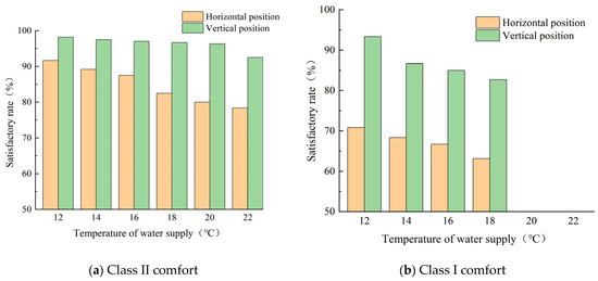
Figure 32.
Comfort attainment of radiant roof combined with advected-jet air conditioning system at different water supply temperatures.
As shown in Figure 30, the comfort attainment rate of the single-side-wall radiant combined with the adherent-jet air conditioning system in the horizontal position rises with the decrease in water supply temperature, and the comfort attainment rate of level II in the horizontal position is above 70%, with a maximum of 92.5%, which is mainly limited using the indoor temperature, and the high water supply temperature leads to the slow decrease in the indoor temperature, which results in the low comfort attainment rate; the highest comfort attainment rate is found at 0.7 m away from the east wall in the vertical direction; the lowest comfort attainment rate is found at 3.3 m away from the east wall due to the installation of radiant cooling panels. A 0.7 m distance from the east wall has the highest comfort attainment rate, and 3.3 m from the east wall has the lowest comfort attainment rate, because the radiant cold plate is installed at the east wall, and the farther away from the radiant cold plate, the higher the air temperature is, and the lower the comfort attainment rate is; the Class I comfort attainment rate of the single-side-wall radiant combined with the adherent-jet air conditioning system is relatively high in the case of low-temperature water supply cooling, with the highest rate reaching 90.83%, but the comfort attainment rate of the single-side-wall radiant combined with the adherent-jet air conditioning system in the cases of water supply temperatures of 20 °C and 22 °C is relatively high, with the highest rate reaching 92.5%. However, when the water supply temperature is 20 °C and 22 °C, the compliance rate of level I comfort is 0, which is not up to the requirement of level I comfort.
As shown in Figure 31, the attainment rate of level Ⅱ comfort of the symmetric-wall radiation combined with the adherent-jet air conditioning system is relatively stable in the horizontal position and vertical position, and the comfort attainment rate in the horizontal position is above 80%, and the comfort attainment rate in the vertical position is about 97%, which is mainly due to the fact that the cooling and dehumidifying efficiency of the symmetric-wall-radiation air conditioning is relatively fast, and it can reach the standard of level Ⅱ comfort very quickly. Symmetrical-wall radiation combined with the attached-jet air conditioning system in the vertical direction of level I of the comfort attainment rate is relatively stable, and the horizontal direction of the comfort attainment rate at different water supply temperatures varies greatly, up to 88.33%, the lowest being 68.33%, although symmetrical-wall radiation combined with the attached-jet air conditioning system regarding the cooling and dehumidification ability is stronger, but due to the radiation plate installation height of 0.4~2.4 m, there is a lag in the cold air sinking and descending to the working area, and the lower the indoor temperature, the faster the rate of cold air sinking, so the level Ⅰ comfort attainment rate of the horizontal position has a larger variation at different water supply temperatures.
As shown in Figure 32, the level II comfort attainment rate and level I comfort attainment rate of the horizontal position of the top-plate radiation combined with the attached-jet air conditioning system are relatively stable, but the level I comfort attainment rate is 0 when the water supply temperature is 20 °C and 22 °C, mainly because the indoor temperature does not reach the level I comfort standard; The vertical position of the radiant roof combined with adherent jet air-conditioning system had a maximum of 91.67% and a minimum of 78.33% for Class II comfort attainment, and a maximum of 70.83% and a minimum of 63.14% for Class I comfort attainment; the top-plate radiation combined with the attached-jet air conditioning system’s level II comfort compliance rate and level I comfort compliance rate are both decreasing with the increase in water supply temperature, which is mainly due to the fact that the radiant cold plate of the top-plate radiation combined with the attached-jet air conditioning system is installed at the top of the room, and the high-temperature air exchanges heat with the radiant cold plate, which is mainly due to the fact that the top-plate radiant cold plate is installed at the top of the room, and the high-temperature air exchanges heat with the radiant cold plate. This is mainly because the radiant cold plate of the roof radiation combined with the attached-jet air conditioning system is installed at the top of the room, and the high-temperature air exchanges heat with the radiant cold plate, and the low-temperature air after heat exchanging needs a certain time to settle, and there is a certain hysteresis.
In summary, the symmetrical-wall radiation combined with the attached-jet air conditioning system has the highest level II comfort attainment rate, and the level I comfort attainment rate is also the highest. When choosing the single-side-wall radiation combined with the attached-jet air conditioning system and the top-plate radiation combined with the attached-jet air conditioning system, attention should be paid to the selection of the water supply temperature, and a lower water supply temperature should be selected as much as possible.
4. Conclusions
In this paper, according to the installation location of the radiation cold plate and adherent jet airflow organization, the system is divided into a single-side-wall radiation combined with the adherent-jet air conditioning system, symmetrical-wall radiation combined with the adherent-jet air conditioning system, and the top-plate radiation combined with the adherent-jet air conditioning system in three forms of the system, and through the construction of the experimental system and experimental research on the indoor heat and humidity environment under the three forms of the system, and based on the results of the experiments, the following conclusions are obtained:
(1) For three kinds of air conditioning systems regarding the air supply volume and air supply temperature and humidity under the premise of maintaining them as the same, the optimal water supply temperature is 18 °C, 22 °C, and 16 °C, while in the above, water supply temperature of the human body under the temperature of the working area is closer to the indoor design temperature of 26 °C; the average temperature of the working area is 26 °C, 26.3 °C, and 26.4 °C, and the working area’s average humidity is 58%, 53%, and 57%, respectively; after the indoor heat and humidity environment is stabilized, the human thermal sensation PMV is 0.47, 0.42, and 0.36, respectively, and the percentage of the dissatisfied people PPD index is expected to be 10%, 9%, and 10%, respectively, which all satisfy the requirements of China’s Class II comfort, and the Class II comfort attainment rate within 10 h of the operation of the air conditioning system is 85%, 89.33%, and 87.5%, respectively, and at the same time, the air conditioning system can also meet the requirements of our country’s level Ⅰ comfort degree, and the level Ⅰ comfort degree compliance rate is 50.83%, 68.33%, and 66.67%, respectively.
(2) After the three air conditioning systems are operated for 10 h at the water supply temperatures of 18 °C, 22 °C, and 16 °C, respectively, the symmetrical-wall radiation combined with the adherent-jet air conditioning system had the lowest energy consumption at the radiant end, and the roof radiation combined with the adherent-jet air conditioning system had the highest energy consumption, with the energy consumption at the radiant end being 5.71 kW·h, 3.99 kW·h, and 10.81 kW·h, respectively.
(3) Symmetrical-wall radiation combined with the attached-jet air conditioning system and top-plate radiation combined with the attached-jet air conditioning system in the room of the human activity area of the vertical plane position and the horizontal height position of the comfort level are relatively uniform, and personnel can be in a relatively uniform distribution; one-sided-wall radiation combined with the attached-jet air conditioning system of the horizontal height of the comfort level is relatively uniform, but in the vertical plane position, the closer the radiating cold plate, the higher the comfort level, so the personnel need to be in the cold plate, meaning the higher the comfort level. Comfort is higher, so personnel need to be placed as close as possible to the radiant cold plate.
(4) Under the same water supply temperature and air supply conditions, the heat exchange per unit of radiant-cold-plate area of the top-plate radiation combined with the attached-jet air conditioning system is the largest, and the heat exchange per unit of radiant-cold-plate area of the symmetric-wall radiation combined with the attached-jet air conditioning system is the smallest; the symmetric-wall radiation combined with the attached-jet air conditioning system is the fastest in cooling and dehumidifying efficiency, and the top-plate radiation combined with the attached-jet air conditioning system is the worst in cooling and dehumidifying efficiency. When creating the same indoor heat and humidity environment, the top-plate radiation combined with the attached-jet air conditioning system has the greatest energy consumption at the end of the radiation, and the symmetrical-wall radiation combined with the attached-jet air conditioning system has the smallest energy consumption at the end of the radiation, so when choosing a radiant air conditioning system, give priority to the symmetrical-wall radiation combined with an attached-jet air conditioning system.
Author Contributions
Z.Z., formal analysis, investigation, methodology, writing—original draft; Y.C., formal analysis, investigation, methodology, writing—original draft; C.L. and X.B., designed system and collected data; J.Z. and S.L., data and picture processing. All authors have read and agreed to the published version of the manuscript.
Funding
In this paper, the research was sponsored by the Natural Science Foundation of Shandong Province (Grant No. ZR2022ME102), the Plan of Introduction and Cultivation for Young Innovative Talents in Colleges and Universities of Shandong Province (2021), and the Scientific and Technological Innovation Project for Youth of Shandong Provincial Colleges and Universities (Grant No. 2019KJH012); the Research on the Development of Intelligent Management System and Energy Saving Technology for Public Hospital Building Energy Use (Grant No. GYZ2022HQ44); and the Shandong Province Science and Technology Small and Medium Enterprises Innovation Ability Enhancement Project (Grant Nos. 2023TSGC0052, 2023TSGC0074); the Research Fund for the Taishan Scholar Project of Shandong Province (tsqn202306064).
Data Availability Statement
Not applicable.
Acknowledgments
The authors of this study wish to acknowledge the contributions of all partners.
Conflicts of Interest
The authors declare no conflict of interest.
References
- Building Energy Efficiency Research Center, Tsinghua University. China Building Energy Efficiency Annual Development Research Report 2022 (Public Buildings Topic); China Building Industry Press: Beijing, China, 2022. [Google Scholar]
- Energy Consumption Statistics Committee of China Building Energy Efficiency Association. 2018 China building energy consumption research report. Architecture 2019, 874, 26–31. [Google Scholar]
- Pan, L.; Wang, S.; Wang, J.; Xiao, M.; Tan, Z. Research on central air conditioning systems and an intelligent prediction model of building energy load. Energies 2022, 15, 9295. [Google Scholar] [CrossRef]
- Zhang, G.; Fu, K.; Zhang, F.; Xu, Z.; Zhang, Y. Multi-objective optimization of load ratio of residential radiant cooling-independent fresh air conditioning system. J. Hunan Univ. (Nat. Sci. Ed.) 2020, 47, 158–168. [Google Scholar]
- Causone, F.; Corgnati, S.P.; Filippi, M.; Olesen, B.W. Experimental evaluation of heat transfer coefficients between radiant ceiling and room. Energy Build. 2009, 41, 622–628. [Google Scholar] [CrossRef]
- Zarrella, A.; De Carli, M.; Peretti, C. Radiant floor cooling coupled with dehumidification systems in residential buildings: A simulation-based analysis. Energy Convers. Manag. 2014, 85, 254–263. [Google Scholar] [CrossRef]
- Mustakallio, P.; Bolashikov, Z.; Rezgals, L.; Lipczynska, A.; Melikov, A.; Kosonen, R. Thermal environment in a simulated double office room with convective and radiant cooling systems. Build. Environ. 2017, 123, 88–100. [Google Scholar] [CrossRef]
- Do, H.Q.; Luther, M.B.; Amirkhani, M.; Wang, Z.; Martek, I. Radiant conditioning retrofitting for residential buildings. Energies 2022, 15, 449. [Google Scholar] [CrossRef]
- Tang, F. Indoor Thermal Safety of Low Temperature Air Supply Cooling Radiant Ceiling Air Conditioning System; Shanghai University of Applied Sciences: Shanghai, China, 2020. [Google Scholar]
- Zhou, X.; Ding, Y.; Deng, Y. Characterization of dew condensation on cooled radiant plate under the operation mode of adsorbed jet variable fresh air. Fluid Mach. 2021, 49, 20–25+40. [Google Scholar]
- Zhou, G.; Yin, L.; Zhou, S. Comparative analysis of adsorption jet-radiation cold plate and displacement ventilation-radiation cold plate. J. Jiangsu Univ. Sci. Technol. (Nat. Sci. Ed.) 2012, 26, 472–476. [Google Scholar]
- Jin, W.; Wang, C.; Cui, F.; Wang, Z.; Yu, Z. Study on the effect of fresh air supply method on the cooling capacity of radiant ceiling. Fluid Mech. 2020, 48, 79–82+88. [Google Scholar]
- Sun, Y. Performance Study of Composite Air-Conditioning System with Adherent Jet and Radiant Cooling Roof; Hunan University: Changsha, China, 2015. [Google Scholar]
- Shi, Y.; Chen, Y.P.; Kong, X.L.; Zhou, G.M. Air quality study of a composite air-conditioning system with radiant cooling and advective jet. HVAC 2011, 41, 60–63. [Google Scholar]
- Zhao, Z.C.; Yun, L.; Zi, X.L.; Feng, W.X. Study on indoor air quality in a composite air-conditioning system with radiant cooling and advective jet. Fluid Mech. 2015, 43, 70–74. [Google Scholar]
- Wu, X.; Wu, F.; Liu, M.; Liu, G.L.; Gao, J. Effects of ventilation mode on human thermal sensation and skin temperature in radiantly air-conditioned rooms. HVAC 2022, 52, 104–112. [Google Scholar]
- Zhang, Z. Numerical Simulation Study of a Composite Air-Conditioned Room with Radiant Cooling Coupled with Advective Jets at the Roof Plate; North China University of Water Resources and Hydropower: Zhengzhou, China, 2018. [Google Scholar]
- Zi, X. Research on Indoor Thermal Environment of Radiant Cooling Composite Air-Conditioning System; Jiangsu University of Science and Technology: Zhenjiang, China, 2014. [Google Scholar]
- Wu, H.; Xu, Q. Optimization of composite air-conditioning system with adherent jet and radiant cold plate. Refrig. Air Cond. 2020, 20, 35–39+53. [Google Scholar]
- Zhang, H. Experiment and Simulation on the Performance of Radiant Cooling System under Different Air Supply Methods with Multiple Radiant Surfaces; Nanjing Normal University: Nanjing, China, 2020. [Google Scholar]
- Xiao, R.; Weng, W.; Zhang, Z. Influence of localized heat source of curtain closure on radiant ceiling cooling. China Water Transp. (Second Half) 2021, 21, 38–40. [Google Scholar]
- JGJ142-2012; Radiation Heating and Cooling Technical Regulations. China Building Industry Press: Beijing, China, 2012.
- GB50736-2012; Design Code for Heating, Ventilation and Air Conditioning for Civil Buildings. China Building Industry Press: Beijing, China, 2012.
- Shen, W. Study on the Indoor Thermal and Humidity Environment and Particle Distribution of Radiant Cooling and Advection System; Shandong University of Architecture: Jinan, China, 2021. [Google Scholar]
- Tartarini, F.; Schiavon, S.; Cheung, T.; Hoyt, T. CBE thermal comfort tool: Online tool for thermal comfort calculations and visualizations. SoftwareX 2020, 12, 100563. [Google Scholar] [CrossRef]
Disclaimer/Publisher’s Note: The statements, opinions and data contained in all publications are solely those of the individual author(s) and contributor(s) and not of MDPI and/or the editor(s). MDPI and/or the editor(s) disclaim responsibility for any injury to people or property resulting from any ideas, methods, instructions or products referred to in the content. |
© 2023 by the authors. Licensee MDPI, Basel, Switzerland. This article is an open access article distributed under the terms and conditions of the Creative Commons Attribution (CC BY) license (https://creativecommons.org/licenses/by/4.0/).