Article

Flexural Behaviour of Lightweight Reinforced Concrete Beams Internally Reinforced with Welded Wire Mesh

by
Pavithra Chandramouli
1,*,
Dinesh Muthukrishnan
1,
Venkatesh Sridhar
1,
Veerappan Sathish Kumar
2,*,
Gunasekaran Murali
3,4 and
Nikolai Ivanovich Vatin
3
1
Department of Civil Engineering, SRM Institute of Science and Technology, Chennai 603203, Tamil Nadu, India
2
Faculty of Civil Engineering, Architecture and Geodesy, University of Split, 21000 Split, Croatia
3
Peter the Great St. Petersburg Polytechnic University, 195251 St. Petersburg, Russia
4
Division of Research & Innovation, Uttaranchal University, Dehradun 248007, Uttarakhand, India
*
Authors to whom correspondence should be addressed.
Buildings 2022, 12(9), 1374; https://doi.org/10.3390/buildings12091374
Submission received: 2 July 2022 / Revised: 22 July 2022 / Accepted: 15 August 2022 / Published: 3 September 2022

Abstract

:
Lightweight clay aggregate (LECA) is manufactured by heating clay with no lime content in the kiln; as a result, the water evaporates and angular clay balls with pore structures are obtained. LECA possess internal curing properties as any other lightweight aggregate due to their pore structure and higher water absorption capacity. In this work, experimental and analytical behaviour using LECA as a 100% replacement for coarse aggregate to make lightweight concrete (LWC) beams was studied. The LWC beams were compared to the conventional concrete beams in load-deflection, energy absorption capacity, and ductility index. Internal mesh reinforcement using welded wire mesh (WWM) of (4 layers of 15 mm square spacing, 4 layers of 10 mm square spacing, and 4 layers of 15 mm and 10 mm mesh placed alternatively) was provided to enhance the load-carrying capacity of the LWC beam without increasing the dimensions and self-weight of the beams. The beam internally reinforced with WWM exhibited higher load carrying capacity and withstood more significant deflection without sudden failure. The internal reinforcement of WWM is provided to make steel rebars, and WWM works monolithically while loading; this will reduce the stress on tension bars and increase load-carrying capacity. Finally, the generated analytical findings agreed well with the experimental data, demonstrating that the analytical model could mimic the behaviour of LWC beams with WWM.

1. Introduction

The use of a normal concrete beam (NCB) has been followed for many years and exhibits good structural behaviour. The aggregate used in the normal concrete is manufactured from natural stones. Concrete is the second most used resource after water; it is used at approximately one ton per human being [1,2]. The strength of the concrete mainly depends on the aggregate used [3]. Due to the higher density of the stone aggregate, the dead load of normal concrete will be heavy [4]. Additionally, due to the rapid usage of these natural sources, we may run into a shortage of these sources in the future, so it is necessary to replace these aggregates with new materials, which should reduce the self-weight of the beam and also should not compromise with the strength aspects [5]. Various materials such as coconut shells, pumice stones, and fibres are used in the concrete mix to manufacture LWC. Many countries have started using lightweight building materials for high-rise structures and other construction purposes, but Asian countries have yet to use this lightweight material in construction [6]. LWC is made by reducing the density of the concrete, which is achieved by replacing the aggregate used in conventional concrete; the most commonly used lightweight aggregates are expanded clay aggregate pumice stones and Styrofoam balls [7]. LWC poses good thermal properties due to more voids produced during aggregates heating and a good weight/strength ratio [8,9,10]. In this research, lightweight clay aggregates (LECA) were used. This implies that baked clay balls can absorb a small amount of water and expand as they do so. This clay aggregate is made from special clay with little or no lime content. The clay is heated in a kiln at a temperature from 1200 °C to 1300 °C; the aggregate formed is in the shape of potato due to the round shape of the kiln. Due to the high porosity created due to heating and escaping of gases, the aggregate has less weight with reduced density. The water absorption is higher due to the increased porosity [6,11,12,13]. LWC poses density from 1700 kg/m3 to 2000 kg/m3 [14,15]. Lightweight concrete reduces the structure’s self-weight, reducing the construction cost and minimising the damage during seismic loadings [16,17]. LWC beams exhibit more cracks rapidly than normal conventional beams, and hence mesh reinforcement is provided to improve the ultimate load-carrying capacity of the bean and reduce the formation of cracks. The mesh reinforcement is used to improve the beam’s ductile behaviour and arrest the crack development in the beam [18]. The mesh reinforcement is used as it will not increase the weight of the beam, and the mesh possesses a high weight-to-strength ratio [19]. Welded wire mesh (WWM) increases reinforced concrete (RC) beams’ flexural and shear behaviour [20,21,22]. WWM are low-cost and easy to handle and transform to any desired shape [23,24]. The common types of mesh used commonly are welded wire mesh, expanded wire mesh, glass fibre mesh, fibre-reinforced polymer, and many composites and hybrid meshes [25]. Rajai Al-rousan studied the effect of WWM as internal reinforcement in heat-damaged RC beams. The beam reinforced with one layer of carbon fibre reinforced polymer (CFRP) and the beam reinforced with one to five layers of WWM were compared based on structural and ductile behaviour. It showed that the cracks increase with the increase in temperature, but the crack width is reduced by increasing the number of WWM reinforcement layers. The technique of providing WWM as internal reinforcement improved the strength, energy absorption and ultimate deflection of the beam and the technique of providing WWM as internal reinforcement can be done with ease which eliminates the use of epoxy or any anchoring systems [26]. The strength obtained for LECA concrete in this study was 37 Mpa to 62 Mpa and the air dry density varied from 1600 to 1850 kg/m3 [27]. Numerous studies have been carried out on LWC by replacing the conventional aggregates partially or completely. However, studies on the behaviour of LWC with the use of WWM as an internal reinforcement have not been reported with finite element model (FEM) analysis.
This paper studied the experimental and analytical behaviour of LWC beam by replacing coarse aggregate 100% with LECA and compared it to the conventional concrete beam for four-point loading in terms of ultimate load carrying capacity and strength. Additionally, four layers of WWM reinforcement with different mesh spacing were provided internally to enhance the flexural behaviour of light weight concrete (LWC) beam to study the effect of spacing of WWM while internally reinforcing it with reinforcement bars. The complexity of improving the strength without increasing the self-weight and size of the structure [28]. A finite element model (FEM) of beams was analysed using ABAQUS to validate the experimental results. ABAQUS is a powerful FEM tool which is often used in analysing structural members. ABAQUS can have wide input varieties and give accurate results matching the experimental value. Many models can be used to analyse concrete beams in ABAQUS. In this experiment, a concrete damage plasticity model (CDPM) was created and the tensile and compression damage of the beams were analysed and give good output of tensile and compression damage of the tested beams [29].

2. Material Properties

2.1. Cement

The cement used in this experiment is ordinary Portland cement (OPC) 53-grade cement. The cement’s specific gravity and consistency are experimentally obtained by performing the suitable test according to IS 12269:2013 [30]. Table 1 represents the properties of cement.

2.2. Fly Ash

Fly ash is very fine and improves fresh concrete’s flow properties. Fly ash is used as cement replacement in concrete for about 15 to 35%, and it is a by-product procured from Ennore thermal power plant, India. IS 3812:2003 [31] gives the guidelines for the utilisation of fly ash in concrete. It appears dark grey with an average spherical particle size of 75 microns, which has a specific gravity of 2.30. Table 2 depicts the chemical composition of fly ash. In this study, 25% of fly ash has been used as cement replacement.

2.3. Aggregates

Coarse aggregate (CA) refers to irregular and granular materials such as sand, gravel, or crushed stone used to make concrete. In most cases, Coarse is naturally occurring and can be obtained by blasting quarries or crushing them by hand or crushers. It is imperative to wash them before concreting. Their angularity and strength affect the concrete in numerous ways. The specific gravity, crushing, and impact strength are obtained by testing the materials according to IS 2386:1963 part 4 [32]. The fine aggregate (FA) used in this research work is M-sand procured from Uthiramerur quarry, Tamil Nadu, India, conforming to Zone II as per IS 383:2016 [33]. The physical properties of FA are listed below in the table. The CA used in this study had a maximum size of 12.5 mm, conforming to IS 383:2016 [33]. Table 3 represents the properties of fine and coarse aggregate.

2.4. Expanded Clay Aggregate

LECA has a pores structure and looks like a small brown clay ball. The appearance of LECA is shown in Figure 1. The properties of lightweight clay aggregates were found using the same method followed for CA. The specific gravity of lightweight aggregate is significantly less than stone aggregates, and LECA in wetted surface dry condition floated while testing for specific gravity in pycnometer. It indicated that the specific gravity must be below 1 and the manufactures data was considered for the property. The crushing strength of the LECA concrete was also less compared to stone aggregate. The density of LECA is 288 kg/m3, almost ten times less than stone aggregate, so a small amount of LECA can fill a large volume. The water absorption for LECA was measured in wetted surface dry condition and was found to be 20%.
The properties of LECA found in this experiment and properties of LECA found in other experimental studies are shown in Table 4.

2.5. Welded Wire Mesh

The steel wire mesh is made by welding steel wires in closed spacing. Mesh is generally used in fencing and plastering to avoid delamination and reduce the crack development in beam and slab by wrapping this over the top of the structural element. The welded wire mesh used in this experiment is shown in Figure 2. The welded wire mesh used in this experiment has a square spacing of 10 mm and 15 mm with a diameter of 1.5 mm. The yield strength and young’s modulus of the WWM are 350 Mpa and 190 Gpa, respectively.

2.6. Concrete Mix Preparation

LECA has very high-water absorption compared to stone aggregate because of its porous structure, so the appropriate correction was done in the water added to the mix. The water absorption of LECA is about 20%, so an additional amount of 20% water was added to compensate for this water absorption to get a proper mixture. The compressive strength of lightweight concrete will be lesser than conventional concrete. The cementitious content must be increased to enhance the strength of the LWC. The cementitious materials used in this experiment partially replaced cement with fly ash and silica fume. The concrete mix proportions are shown in Table 5.
The compressive strength of normal concrete after 28 days of curing was 25 Mpa and that of lightweight concrete was 23 Mpa, and 10% of silica fume was added to the desired strength for the lightweight concrete mix. The density of conventional concrete was 2500 kg/m3, and the density of lightweight concrete was 1700 kg/m3, which is acceptable according to ACI 213R-14 [7].

3. Experimental Setup

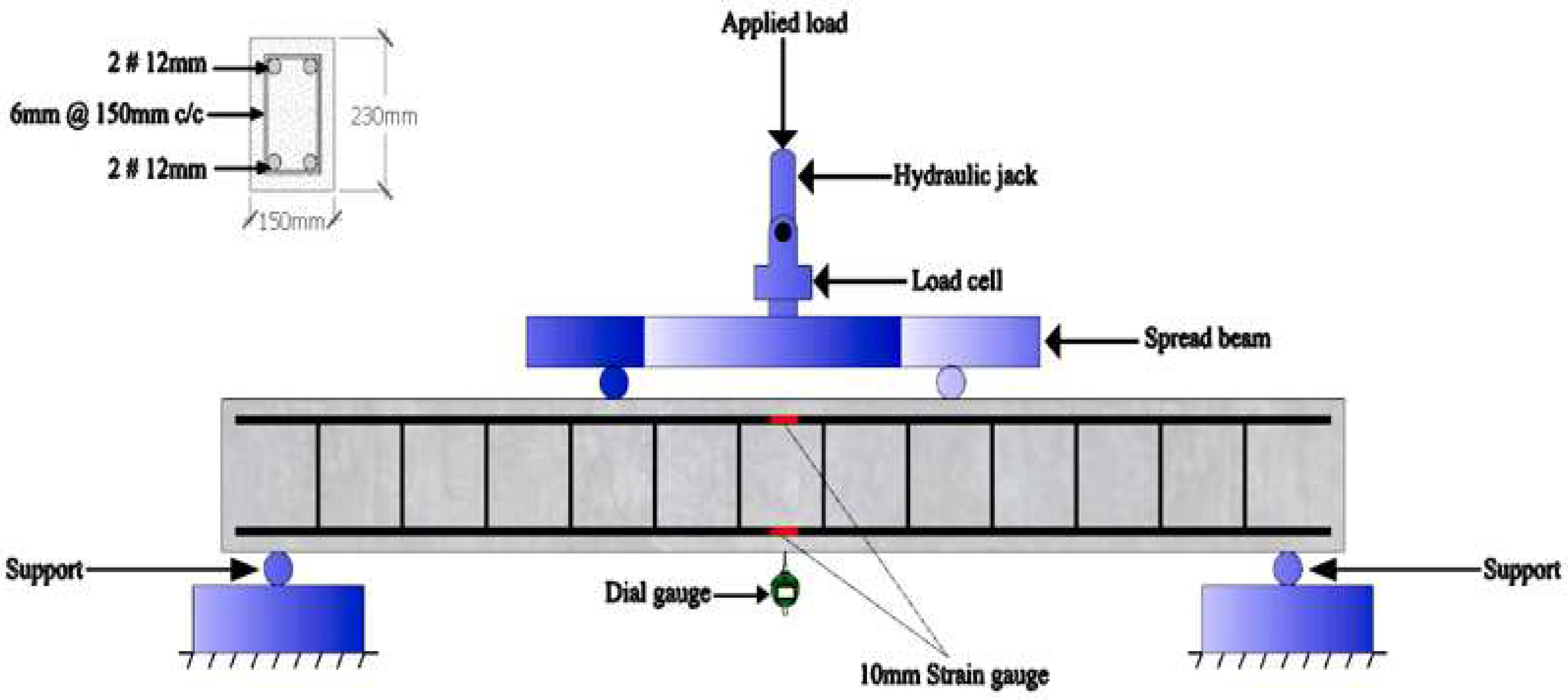
3.1. Specimen Details

The flexural behaviour of reinforced NWC and LWC beams was studied in two cases: beams with and without internally reinforced with WWM. The section was determined as under-reinforced/over-reinforced using the limit state design method as per IS 456: 2000 [20]. Five beams were tested, of which one was NWC and four were LWC. Two numbers of Fe500 high yield strength deformed bars (HYSD) of 12 mm diameter were used at the tension and compression zones. Additionally, 6 mm diameter two-legged stirrups spaced at 150 mm centre to the centre were used throughout the length of the beam. The welded wire mesh with different spacing was used as internal reinforcement in the LWC beam. Figure 1 shows the reinforced bars and mesh. The internal reinforcements of WWM with steel rebars are shown in Figure 3. The specimen details are given in Table 6.
The reinforcement was provided according to IS 456-2000 [37], and the reinforcements provided are twice the minimum reinforcement required for the beam as per IS 456-2000 [37].

3.2. Casting of Beams

Wooden formwork was used to cast the concrete, as shown in Figure 4. The sides and the bottom were firmly fastened using bolts to avoid gaps. Cement masonry cover blocks of 25 mm thickness were used at the bottom and sides to maintain the clear cover for the beams. The dry mix ingredients were mixed in the concrete mixer for about 4–5 min. The water and the admixture were added to the dry mix. The wet mixture was layered and compacted using a needle vibrator to prevent the voids and honeycombing in the concrete. The formwork was demoulded after 24 h of casting. The gunny bags were used for curing to avoid hydration and evaporation loss.

3.3. Curing of Concrete

The expanded clay aggregate absorbs water during the concrete mix process and curing. This absorbed water aids the internal curing of concrete in the early stages of the curing process. The internal curing prevents early shrinkage cracks in concrete by providing a constant supply of water from inside. The internal curing also reduces the permeability and increases the strength of the concrete. The water absorption by LECA is shown in Figure 5.
The internal curing process prolongs the hydration process, which reduces early crack formation and concrete, increases concrete durability, and reduces pore formation, which aids in minimising chemical attacks on concrete. The internal surface of the concrete after hardening is shown in Figure 6.
It may be noted that the absorbed water by LECA did not percolate inside. It remained only on the outer layer of the aggregate, so this will not affect the strength of the aggregate or concrete. The absorbed water will aid in the internal curing process.

3.4. Loading Setup

After 28 days of curing, the beams were tested using a self-straining loading frame with a four-point loading setup, as shown in Figure 7. Before testing, all the beams were whitewashed to make it easier to observe the crack patterns. The beam was supported 100 mm from the beam ends and maintained a clear span of 1800 mm from the supports. Two circular steel rods were placed at one-third distance of beam clear span, and a spread beam was placed over the steel rods to distribute the loads evenly. The load cell of capacity 1000 kN was placed on top of the spread beam, and the load was gradually applied until failure using a hydraulic jack. The load was maintained throughout the test, and the loading rate was kept incremental at 1 kN/min until the beam collapsed. Strain gauges of 10 mm were installed near the centre in tension and compression face of reinforcing bars to monitor the strain. The gauges on the bars were ground smooth with sandpaper to ease installing the strain gauges and a gauge resistance of 120 ohms was checked using a multimetre. The strain was recorded using the data logger. A dial gauge was positioned at the bottom centre of the beam to monitor the deflection at every loading stage.

4. Result and Discussions

4.1. General

The weight reduction of about 40% is achieved using LECA as coarse aggregate in the concrete. This weight reduction reduces the self-weight of the beam to a greater extent, which will help reduce the steel reinforcement provided in the beam, column, and footing. The concept of a weak beam-strong column can be achieved by casting the beam with LECA concrete. The flexural behaviour of the internally reinforced beams with WWM was better than the conventional and LWC beams. The analytical failure patterns are also compared to the experimental failure of the beam. The experimental and analytical tensile damage was almost similar, although there was a slight difference in some places. The values of ultimate load, ultimate deflection, and ultimate tensile strain are shown in Table 7. It can be seen that the tensile increase with the reducing spacing of WWM and the ultimate load is higher for beam internally reinforced with closely spaced WWM.

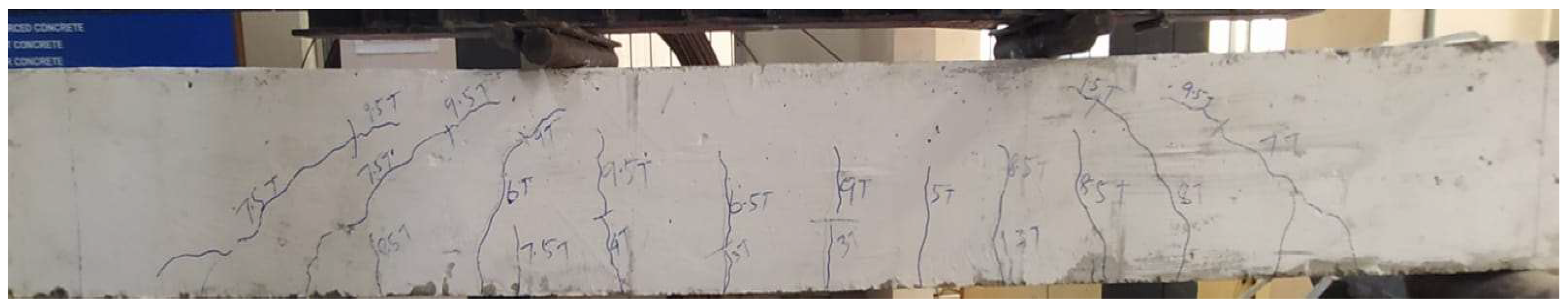
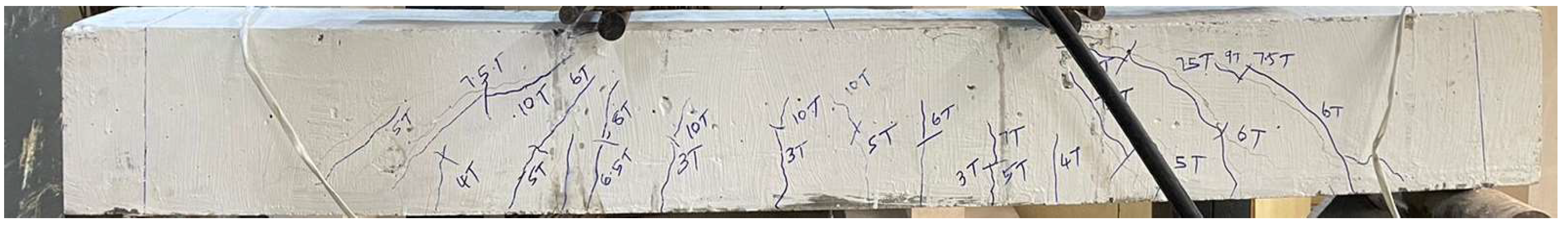
4.2. Structural Observation

The cracks were observed at every 5 kN increase in the load. The failure of the beam was reached due to the yielding of steel reinforcement, followed by the crushing of concrete in compression zone. The crack and failure patterns of both NWC and LWC were almost similar. The LWC beams reinforced with mesh were able to carry more load compared to NWC and LWC beams without mesh reinforcement. The load-carrying capacity varied with the mesh spacing; the mesh with closer spacing had more load than those with bigger spacing. The crack development in LWC beams was more rapid, and the width of the cracks was bigger in LWC beams as we expected, but the load-carrying capacity of conventional beams and LWC beams were almost the same. Figure 8 and Figure 9 show the experimental damage pattern of the beam.

4.3. Comparison of NWC and LWC Beam

4.3.1. Failure Modes

It can be seen from Figure 8 and Figure 9 that the crack failure pattern of NWC and LWC beams are similar, and the load-carrying capacity of LWC is lesser than the NWC beam. The aggregate used in the LWC concrete has lower crushing strength than the stone aggregate. Hence, LWC fails due to concrete crushing earlier. As predicted earlier, the deflection of LWC beams is higher than NWC beams due to the reduced density of concrete. The tensile strain of both NWC and LWC are similar. Both beams failed due to the crushing of concrete. First, the tension cracks propagated in the tension zone of the beam and then extended gradually towards the compression face on gradual loading.

4.3.2. Load vs. Deflection

The load vs. deflection comparison is graphically represented in Figure 10. It can be observed from Figure 10 that there is not much difference between the NWC and LWC beams. Both beams fail gradually after yielding steel reinforcement and crushing concrete under compression. Additionally, there was no sudden failure of the beam, indicating that the LWC beam acts similar to the conventional beam. The load-deflection curve of LWC and NWC beams is shown in Figure 10.

4.4. Comparison of WWM Reinforced LWC Beams to LWC Beam

4.4.1. Failure Modes

The LWC beams reinforced with four layers of WWM performed better than LWC beams without WWM reinforcement. The load-carrying capacity was increased, and the beam could take loading after the yielding of steel reinforcement as the mesh reinforcement was carrying the load beyond the yielding point of steel reinforcement. The cracking pattern of LWC beam with WWM reinforcement is shown in Figure 8, Figure 9 and Figure 10. It can be seen from the figures that the crack size was reduced with the reduction of mesh spacing. The load-carrying capacity also increased, and the beam sustained larger deflection with rapid crack formation, but the crack width was small. The failure was reached due to the yielding of steel reinforcement followed by the yielding of mesh reinforcement, and then finally, concrete was crushed at the ultimate load. It can be seen from Figure 11, Figure 12 and Figure 13 that the yield points are also reduced compared to the LWC beam without WWM reinforcement. The analytical failure pattern of all the mesh reinforcements was similar. Still, slight changes were observed in the experimental failure pattern of mesh with closely spaced reinforcement and widely spaced reinforcement. There was a slight improvement in the load-carrying capacity of the beam with closely spaced WWM reinforcement.

4.4.2. Load vs. Deflection

The load vs. deflection curve of the LWC with meshes are shown in Figure 14. It can be seen from the figure that the curve has become much more linear compared to the beam without mesh reinforcement. The ductile region curve is much larger than those beams without mesh reinforcement, proving that the mesh reinforcement improved the ductile behaviour of the beams. The beam load carrying capacity improvement is due to the increased tensile reinforcement as the mesh also acts as reinforcement steel in the tension zone. The beam reinforced with mesh with closer spacing has been able to carry more load and withstand more significant deflection without failure.
The deflection at serviceable loads is under permissible limits for the beams. The service load is taken from IS 875:1987 part II [38] for the live load of the structure. Table 8 shows the allowable deflection and deflection at service load for all the beam specimens.

4.5. Analysis of other Mechanical Properties

The beams’ additional mechanical characteristics, including stiffness and energy absorption, were also studied. Stiffness is defined as the ratio of load at the elastic point to the deflection at the elastic (k = p Δ ). The area under the elastic region in the load-deflection curve represents the energy absorption of the beam. Table 9 shows the energy absorption, performance, and strength of the beam. The deformability factor (DF), strength factor (SF), and the performance factor (PF) define the overall structural performance of the beam.

4.5.1. Ductility Study

All the beams pose a ductility ratio ( Δ u Δ y ) of more than 3 [39], and the beam having a ductility ratio between 3–5 can be accepted as a structural member. The ductility ratio of the beam with mesh reinforcement is higher, as the beams take more loading after the yielding of steel as the mesh reinforcement takes the loading beyond the yield point of steel, which makes the beam take a higher load without sudden failure. The ductility ratio of the beams is shown in Table 10.
It is seen from Table 10 that all the beam poses a ductility ratio of more than 3 [40]. The beam having a ductility ratio between 3–5 can be accepted as a structural member.

4.5.2. Ductility Index

The structure ductility is usually measured by a ratio called the ductility index (μ). The structure ductility index is generally expressed in terms of displacement ductility index (μ∆), energy absorption ductility index (μEA), curvature ductility index (μφ), and rotation ductility index (μ) [26]. Table 9 shows the ductility indexes of the beam specimens.

4.5.3. Displacement Ductility Index

The displacement ductility (μ∆) ratio is defined as the displacement at the ultimate stage to the displacement at the yield stage [26]. It can be seen from Table 9 that the displacement index of the beam with mesh reinforcement is higher than the conventional beam. All beams have a ductility index of more than 3. The displacement ductility index of the beams with mesh reinforcement is slightly higher than conventional and LWC beams because of the additional tension reinforcement provided by the mesh. This proves that tying WWM with steel reinforcement internally makes the mesh and steel reinforcement act monolithically as single reinforcement. It can also be observed that the displacement ductility index of the beam reinforced with closely spaced mesh are higher than the beam reinforced with a mesh having higher spacing. The closely spaced mesh provides a higher weight-to-strength ratio. The beams with closely spaced mesh reinforcement provide a higher displacement ductility index.

4.5.4. Energy Absorption Ductility Index
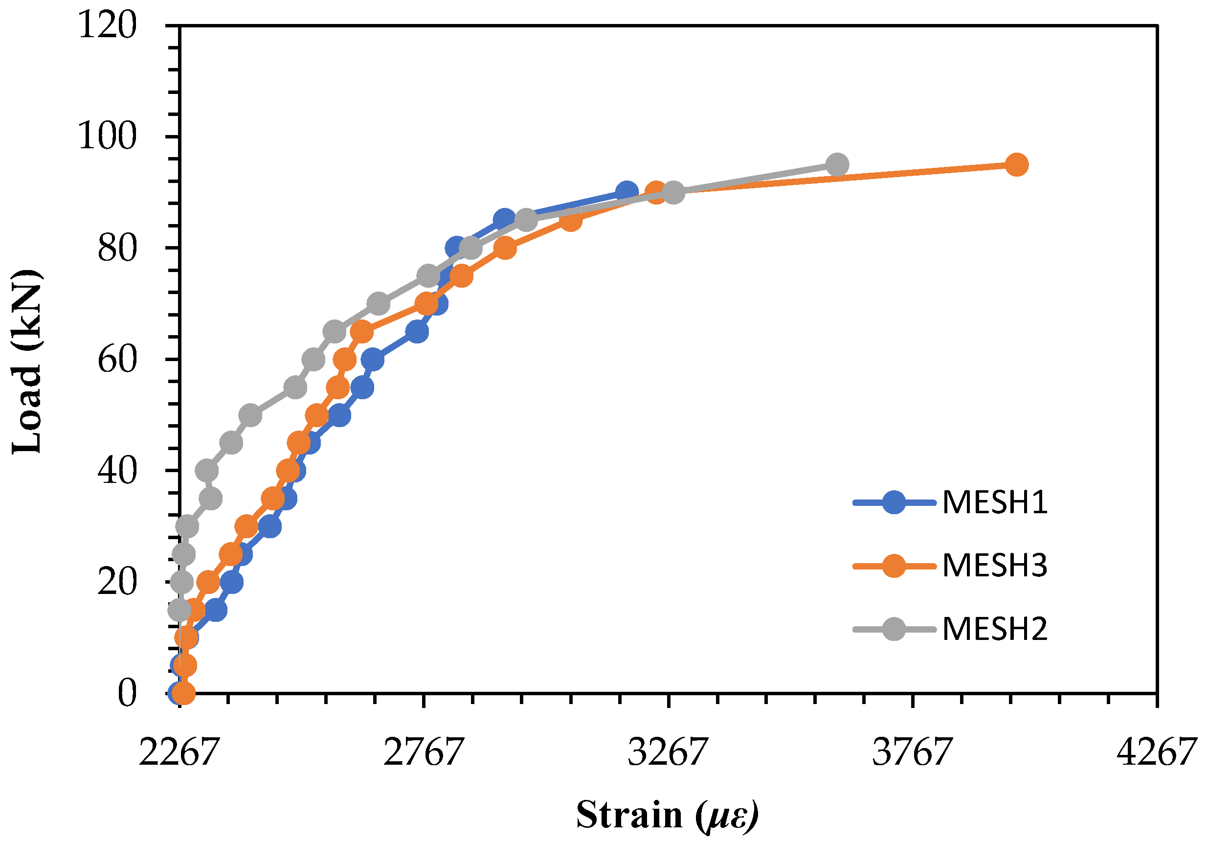
Energy absorption ductility index (μEA) is defined as the ratio of area under the load-deflection curve until failure to the area under the load-deflection under yielding [26]. From Table 9, we can see that the energy absorption index of a beam internally reinforced with mesh is 1.2 times higher than that of conventional and LWC beams without internal mesh reinforcement. The energy absorption of the beams with mesh reinforcement is slightly higher than conventional and LWC beams because of the additional tension reinforcement provided by the mesh. The mesh reinforcement enhances the load strength of the beam, and thus the beam takes more load, so the energy absorption of the beams also increases. The energy absorption of a mesh having closer spacing is higher than the beam reinforced with a mesh, having larger spacing.

4.6. Tensile Strain

The tensile strain steel reinforcement was recorded using a strain gauge fixed to the steel rebars in the tension face. It can be seen from the graph that the strain values increased as the spacing of WWM decreased. This was due to the higher ultimate load value for the beam being internally reinforced with WWM. Figure 15 shows the Load vs. strain graph for LWC and NWC. The strain values for NWC beams were 3980 με and for LWC beam were 3617 με.
Figure 16 shows the Load vs. strain graph for LWC beam with WWM reinforcement. The tensile strain for beams internally reinforced with WWM was higher than LWC beams without WWM reinforcement. The maximum strain value of 3980 με was attained for the beam reinforced with alternate layers of 10 mm and 15 mm WWM spacing. Mesh 2, reinforced with four layers of 10 mm spaced WWM, maintained an elastic behaviour until the yielding point. Hence, it indicates that using four layers of WMM with the same closely spaced WWM performs better in elastic behaviour than beam reinforced with closely spaced WWM by placing alternate layers to reduce the spacing of WWM.

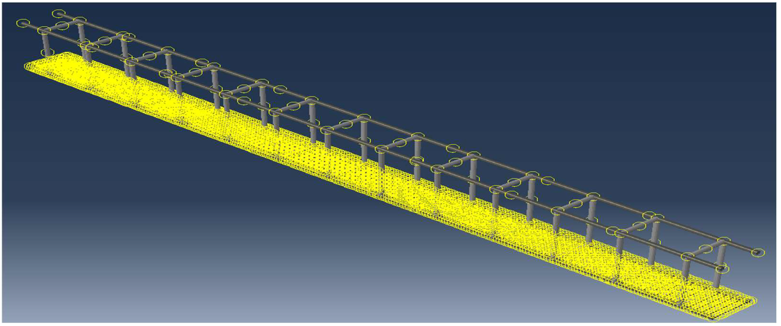
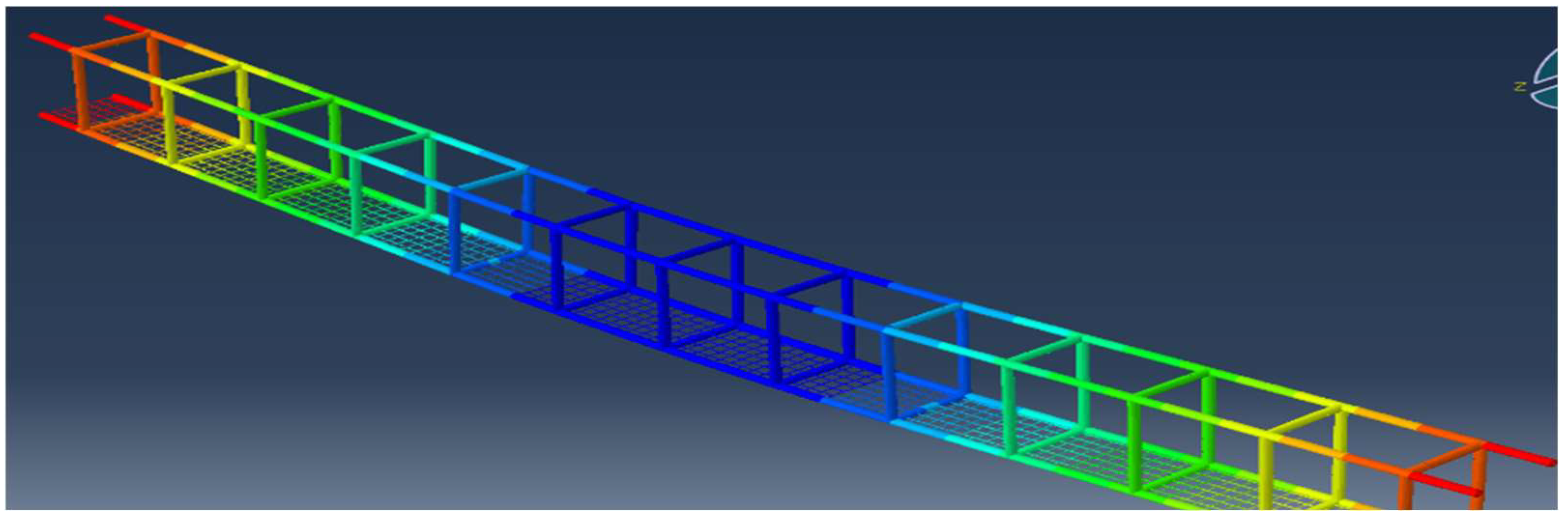
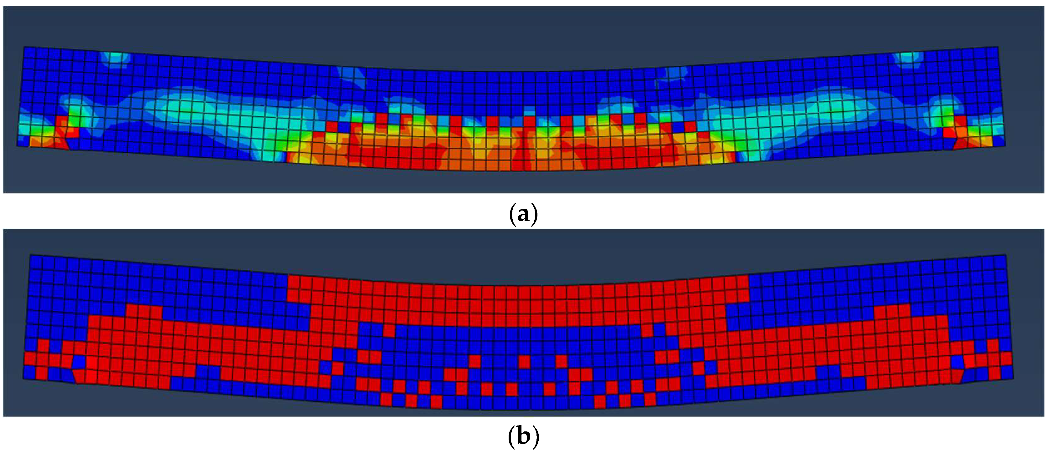
5. Analytical Results

5.1. Analytical Model

This study aims to numerically investigate the effects of LWC beam with mesh reinforcement on flexural behaviour and load-deflection curves of reinforced concrete beams strengthened with mesh reinforcement. For this purpose, three-dimensional finite element models that can accurately simulate reinforced LWC beams strengthening with mesh reinforcement were developed using ABAQUS. The analytical finite element modelling (FEM) was done using ABAQUS software. The geometry of specimens, the applied loadings, and boundary conditions of simulated models was the same in two perpendicular planes. The beam is modelled as a solid homogenous 3D deformable in parts, and the property of concrete is assigned to the beam. To simulate solid materials, including concrete, three-dimensional eight nodes brick elements which were denoted by C3D8R, were used. The C3D8R elements can simulate cracks in tension and compression zones. The properties include density, young modulus, CDPM in concrete compression and tension behaviour. The steel reinforcement main bar, hanger bar and stirrups are created as wire 3D deformable in the parts section. The properties of concrete are given for CDPM, including compression and tension behaviour of the concrete. To simulate structural bars, both beam elements and truss elements can be used. This study used truss elements with three-dimensional mesh discretisation (T3D2) to model structural bars, including steel bars and mesh reinforcement. Young’s modulus, density and Poisson’s ratio for concrete are also assigned. For steel rods, yield strength, young’s modulus and Poisson’s ratio are given. The steel diameter used in the actual experimental beams is mentioned in the section menu in ABAQUS, and the section is assigned to the steel rod. Figure 17 shows the ABAQUS reinforcement model for the steel bars without and with mesh reinforcement.
The interaction between reinforcement and beam is given as an embedded region, and the welded wire mesh and steel reinforcement interact as a tie connection. The interaction of steel reinforcement and mesh is shown in Figure 18.
The model’s output was compared with the experimental outcomes of the (DAMAGET) tensile damage of beam and AC yield output, which show the parts of beam that yield first in the ABAQUS model. The following two outputs are compared to the experimental damage of the beam. Additionally, the load-deflection curve of both experimental and analytical results is compared, and there is not much difference between the analytical and experimental values. Figure 19 shows the displacement of steel reinforcement with WWM, showing that both steel rebars and WWM act as internal reinforcement as desired. The maximum displacement was observed in the centre tensile zone of the beam and its represented by blue colour in Figure 19.
The analytical model was created in ABAQUS. It is a FEM software widely used to analyse structural members in the engineering research field. It can take input of many concrete properties and gives various outputs per our requirement to obtain the analytical behaviour of lightweight and normal concrete beam. The CDPM parameters were assigned for both LWC and NWC beams.

5.2. Analytical Tensile Behaviour of Beams

The concrete tensile damage gives the output of the tensile damage inflicted on the concrete beam when loaded experimentally. The tension damage pattern obtained from the ABAQUS model was comparable to the damage pattern of experimentally tested beams. The red colour square in Figure 20a and Figure 21b shows the yield points of conventional and LWC beams. That will yield first while loading and the blue colour square are unaffected regions. The experimentally tested beams also developed cracks around the same region as the yield points (red square) formed in the analytical model. The Abaqus output model shows the damage pattern of concrete beam under the ultimate load that can be used to understand the failure of the LWC beam. The comparison of damage of analytical and experimental beams were carried out to study the flexural behaviour of rubberised concrete beams strengthened with welded wire mesh [41]. The analytical damage shown in the below figures depicts the damage pattern of the beams, and it can be noted that the region of cracks developed in experimental test was similar to the analytical damage pattern obtained from FEM.
It can be seen from Figure 20a and Figure 21a that the normal-weight concrete beam has developed less tensile damage than the LWC beam. This may be due to the reduced young’s modulus of lightweight concrete, which affects its load-carrying capacity, and the reinforcement takes more load than concrete in this case.
The tensile damage of LWC beams is shown in Figure 21a. It can be seen that there are a lot of yield points formed in the compression zone of the beam. This may be due to the less young’s modulus of lightweight concrete and the aggregates’ lower crushing strength. The concrete has a lesser load-carrying capacity, so they yield rapidly, and this may be the reason for the lesser load-carrying capacity of the beam even though the reinforcement provided are same for all beams. It was seen from Figure 21b that more yield points were formed in the compressive region of beams which was seen in experimental failure pattern that cracks were developed in the compressive face and concrete crushed eventually.
The tensile damage of the LWC beam with WWM is shown in Figure 22a, Figure 23a and Figure 24a. It can be observed that the tensile damage of all the LWC beams reinforced with WWM is similar to the damage pattern recorded during the experimental test. This is because the WWM provided were of the same diameter, and all the WWM were provided in 4 layers. The spacing was different for each beam, and thus there was some improvement in the load-carrying capacity of the beam, but the tensile damage was the same on all the beams.
It can be seen that the yield points in the compression zone are reduced in LWC beams reinforced with WWM. This shows that the WWM improves the load-carrying capacity of LWC Beams than NWC beam of same dimensions, and reduces the beam’s compression stress. The yield points of LWCM1, LWCM2 and LWCM3 are shown in Figure 22b, Figure 23b and Figure 24b. It was observed that the yield points were reduced after introducing WWM in the tensile zone. The WWM reduced the yield point considerably but due to lower young’s modulus the yield points were still formed in the compressive face.

5.3. Analytical Deflection Behaviour

The load-deflection of both lightweight and normal concrete beams was plotted in ABAQUS. The ultimate load obtained in the ABAQUS for NWC beam was 105 kN, and the maximum deflection was 12 mm. The ultimate experimental load for NWC beams was 85 kN with a deflection of 13.95 mm, so the difference between analytical and experimental load is 19%.
The ultimate load for beam internally reinforced with WWM was 100 kN, 115 kN, and 120 kN for an alternate layer of 10 mm and 15 mm WWM, 15 mm WWM, and 1 mm WWM, respectively. The experimental loads were 90 kN, 95 kN, and 100 kN for the following LWC with WWM reinforcement, so the error percentage was around 20% between analytical and experimental values.

6. Conclusions

From the study and comparison of the conventional and LWC beam and with the beam having mesh reinforcement with varying spacings, the following conclusions can be drawn:
  • The load carrying and deflection of conventional and lightweight beams are almost similar. The ultimate load for LWC beam was 75 kN and the deflection under ultimate load was 14.47 mm, and for NWC beams, the ultimate load was 85 kN and the deflection was 13.95 mm. The difference in load-carrying capacity is because of the reduced young’s modulus value of lightweight concrete and lower crushing strength of LECA.
  • The beam reinforced with mesh closely spaced improves the load-carrying capacity of the beam by 19 percentage and reduces the cracks. The beams with closely spaced WWM exhibit lesser compressive stresses than LWC beams without WWM reinforcement.
  • LECA can be used as a replacement for stone aggregate in concrete, and it does not affect the structural aspects of the beams, although there are other factors like creep and fatigue of the LWC concrete with 100% LECA replacement which have to be studied for better understanding. LECA concrete beam with WWM as internal reinforcement can be used to replace conventional beams in suitable works.
  • The mesh reinforcement can be used to provide additional tension reinforcement without increasing the depth of the beam. Internal reinforcement of WWM acts monolithically with reinforcement bars, and tensile reinforcement increases without increasing the beam’s depth. The difference between the ultimate load-carrying capacity of lightweight and NWC Beam was 11% in experimental results.
  • Providing WWM mesh internally to the tension face of beams has proven to be effective in increasing the structural beam performance without increasing the weight of the beam. A 25% increase in load-carrying capacity was achieved by providing internal WWM reinforcement.
  • A weight reduction of about 45% was achieved by replacing granite aggregate with LECA balls. The density of LWC concrete beam is 1600 Kg/m3, which is 60% of conventional concrete beams
  • The analytical and experimental results had an error percentage of about 20%. ABAQUS can be used to analyse LWC beams, as it gives results very similar to the experimental results. The ultimate load difference between LWC and NWC beams was 16% analytically.
  • The 100 percent replacement of normal aggregate has bought only 10% reduction in the ultimate load carrying capacity of LWC beam without any mesh reinforcement. The amount of binder used is much higher for LWC concrete owing to their water absorption and porous structure, which can be countered by using fly ash.
  • The study of durability properties of the LWC concrete using LECA will give a better understanding of this type of concrete’s overall performance, which will be useful for the rational design of structures using LWC concrete.

Author Contributions

Conceptualization, P.C., V.S. and D.M.; methodology, P.C., V.S. and D.M.; validation, P.C., V.S., D.M. and V.S.K.; formal analysis, P.C., V.S. and D.M.; investigation, P.C., V.S. and D.M.; resources, P.C., V.S.K., G.M. and N.I.V.; data curation, V.S.K., G.M. and N.I.V.; writing—original draft preparation, P.C., D.M., V.S., G.M. and N.I.V.; writing—review and editing, P.C., V.S.K., G.M. and N.I.V.; supervision, P.C.; project administration, P.C., V.S.K., G.M. and N.I.V.; funding acquisition, G.M. and N.I.V. All authors have read and agreed to the published version of the manuscript.

Funding

The research was funded by the Ministry of Science and Higher Education of the Russian Federation as the grant Self-Healing Construction Materials (contract No. 075-15-2021-590 dated 4 June 2021).

Institutional Review Board Statement

Not applicable.

Informed Consent Statement

Not applicable.

Data Availability Statement

Not applicable.

Conflicts of Interest

The authors declare no conflict of interest.

References

  1. Melorose, J.; Perroy, R.; Careas, S. Microstructure, Properties, and Materials. Statew. Agric. Land Use Baseline 2015, 1, 684. [Google Scholar]
  2. Lu, S.M.; Lu, C.; Tseng, K.T.; Chen, F.; Chen, C.L. Energy-Saving Potential of the Industrial Sector of Taiwan. Renew. Sustain. Energy Rev. 2013, 21, 674–683. [Google Scholar] [CrossRef]
  3. Unnikrishna Pillai, S.; Menon, D. Reinforced Concrete Design, 4th ed.; McGraw Hill Education: Noida, India, 2021. [Google Scholar]
  4. Libre, N.A.; Shekarchi, M.; Mahoutian, M.; Soroushian, P. Mechanical Properties of Hybrid Fiber Reinforced Lightweight Aggregate Concrete Made with Natural Pumice. Constr. Build. Mater. 2011, 25, 2458–2464. [Google Scholar] [CrossRef]
  5. Nadesan, M.S.; Dinakar, P. Mix Design and Properties of Fly Ash Waste Lightweight Aggregates in Structural Lightweight Concrete. Case Stud. Constr. Mater. 2017, 7, 336–347. [Google Scholar] [CrossRef]
  6. Alengaram, U.J.; Jumaat, M.Z.; Mahmud, H. Ductility Behaviour of Reinforced Palm Kernel Shell Concrete Beams. Eur. J. Sci. Res. 2008, 23, 406–420. [Google Scholar]
  7. ACI. 213R-03 Guide for Structural Lightweight-Aggregate Concrete; ACI Committee: Farmington Hills, MI, USA, 2006; ISBN 9780870318979. [Google Scholar]
  8. Al-Jabri, K.S.; Hago, A.W.; Al-Nuaimi, A.S.; Al-Saidy, A.H. Concrete Blocks for Thermal Insulation in Hot Climate. Cem. Concr. Res. 2005, 35, 1472–1479. [Google Scholar] [CrossRef]
  9. Uysal, H.; Demirboga, R.; Şahin, R.; Gül, R. The Effects of Different Cement Dosages, Slumps, and Pumice Aggregate Ratios on the Thermal Conductivity and Density of Concrete. Cem. Concr. Res. 2004, 34, 845–848. [Google Scholar] [CrossRef]
  10. Al-Khaiat, H.; Haque, M.N. Effect of Initial Curing on Early Strength and Physical. Cem. Concr. Res. 1998, 28, 859–866. [Google Scholar] [CrossRef]
  11. Arioz, O.; Kilinc, K.; Karasu, B.; Kaya, G.; Arslan, G.; Tuncan, M.; Tuncan, A.; Korkut, M.; Kivrak, S. A Preliminary Research on the Properties of Lightweight Expanded Clay Aggregate. J. Aust. Ceram. Soc. 2008, 44, 23–30. [Google Scholar]
  12. Roces, E.; Muñiz-Menéndez, M.; González-Galindo, J.; Estaire, J. Lightweight Expanded Clay Aggregate Properties Based on Laboratory Testing. Constr. Build. Mater. 2021, 313, 125486. [Google Scholar] [CrossRef]
  13. Payam, S.; Chai, L.J.; Mahmud, H.B.; Nomeli, M.A. A Comparison Study of the Fresh and Hardened Properties of Normal Weight and Lightweight aggregate Concretes. J. Build. Eng. 2018, 15, 252–260. [Google Scholar]
  14. Zukri, A.; Nazir, R.; Said, K.N.M.; Moayedi, H. Physical and Mechanical Properties of Lightweight Expanded Clay Aggregate (LECA). MATEC Web Conf. 2018, 250, 01016. [Google Scholar] [CrossRef]
  15. Mahdy, M. Structural Lightweight Concrete Using Cured LECA. Int. J. Eng. Innov. Technol. 2016, 5, 25–31. [Google Scholar] [CrossRef]
  16. Topqu, I.B. Lightweight Concretes Produced by Volcanic Slags. Cem. Concr. Res. 1997, 27, 15–21. [Google Scholar] [CrossRef]
  17. Sajedi, F.; Shafigh, P. High-Strength Lightweight Concrete Using Leca, Silica Fume, and Limestone. Arab. J. Sci. Eng. 2012, 37, 1885–1893. [Google Scholar] [CrossRef]
  18. Fahmy, E.H.; Shaheen, Y.B.I.; Abdelnaby, A.M.; Abou Zeid, M.N. Applying the Ferrocement Concept in Construction of Concrete Beams Incorporating Reinforced Mortar Permanent Forms. Int. J. Concr. Struct. Mater. 2014, 8, 83–97. [Google Scholar] [CrossRef]
  19. Tayeh, B.A.; Abu Maraq, M.A.; Ziara, M.M. Flexural Performance of Reinforced Concrete Beams Strengthened with Self-Compacting Concrete Jacketing and Steel Welded Wire Mesh. Structures 2020, 28, 2146–2162. [Google Scholar] [CrossRef]
  20. El Debs, M.K.; Naaman, A.E. Bending Behavior of Mortar Reinforced with Steel Meshes and Polymeric Fibers. Cem. Concr. Compos. 1995, 17, 327–338. [Google Scholar] [CrossRef]
  21. Abu Maraq, M.A.; Tayeh, B.A.; Ziara, M.M.; Alyousef, R. Flexural Behavior of RC Beams Strengthened with Steel Wire Mesh and Self-Compacting Concrete Jacketing—Experimental Investigation and Test Results. J. Mater. Res. Technol. 2021, 10, 1002–1019. [Google Scholar] [CrossRef]
  22. Paramasivam, P.; Lim, C.T.E.; Ong, K.C.G. Strengthening of RC Beams with Ferrocement Laminates. Cem. Concr. Compos. 1998, 20, 53–65. [Google Scholar] [CrossRef]
  23. Bansal, P.P.; Civil, B.E.; Structures, C. Effect Of Wire Mesh Orientation On Strength Of Beams Retrofitted Using Ferrocement Jackets. Int. J. 2014, 5, 8–19. [Google Scholar]
  24. Haryanto, Y.; Gan, B.S.; Widyaningrum, A.; Wariyatno, N.G.; Fadli, A. On the Performance of Steel Wire Rope as the External Strengthening of RC Beams with Different End-Anchor Types. J. Teknol. 2018, 80, 145–154. [Google Scholar] [CrossRef]
  25. Shaaban, I.G.; Shaheen, Y.B.; Elsayed, E.L.; Kamal, O.A.; Adesina, P.A. Flexural Characteristics of Lightweight Ferrocement Beams with Various Types of Core Materials and Mesh Reinforcement. Constr. Build. Mater. 2018, 171, 802–816. [Google Scholar] [CrossRef]
  26. Al-Rousan, R.Z. The Impact of the Welded Wire Mesh as Internal Reinforcement on the Flexural Behavior of RC Beams Exposed to Elevated Temperature. Case Stud. Constr. Mater. 2021, 15, e00618. [Google Scholar] [CrossRef]
  27. Shafigh, P.; Hassanpour, M.H.; Razavi, S.V.; Kobraei, M. An Investigation of the Flexural Behaviour of Reinforced Lightweight Concrete Beams. Int. J. Phys. Sci. 2011, 6, 2414–2421. [Google Scholar] [CrossRef]
  28. Scislo, L.; Guinchard, M. Non-Invasive Measurements of Ultra-Lightweight Composite Materials Using Laser Doppler Vibrometry System. In Proceedings of the 26th International Congress on Sound and Vibration, ICSV 2019, Montreal, QC, Canada, 7–11 July 2019. [Google Scholar]
  29. Koh, C.G. A Plastic-Damage Model for Lightweight Concrete and Normal Weight Concrete. Int. J. Concr. Struct. Mater. 2008, 2, 123–136. [Google Scholar] [CrossRef]
  30. IS 12269; Ordinary Portand Cement 53 Grade. Bureau of Indian Standards (BIS): Delhi, India, 2013.
  31. IS 3812 (Part-1); Pulverized Fuel Ash—Specification. Part 1: For Use as Pozzolana in Cement, Cement Mortar and Concrete (Second Revision). Bureau of Indian Standards (BIS): Delhi, India, 2003; pp. 1–14.
  32. IS 2386 (Part IV); Methods of Test for Aggregates for Concrete, Part 4: Mechanical Properties. Bureau of Indian Standards (BIS): Delhi, India, 2016; pp. 1–37.
  33. IS 383; Specification for Coarse and Fine Aggregates from Natural Sources for Concrete. Bureau of Indian Standards (BIS): Delhi, India, 1970; pp. 1–24.
  34. Chen, H.J.; Wu, C.H. Influence of Aggregate Gradation on the Engineering Properties of Lightweight Aggregate Concrete. Appl. Sci. 2018, 8, 1324. [Google Scholar] [CrossRef]
  35. Ardakani, A.; Yazdani, M. The Relation between Particle Density and Static Elastic Moduli of Lightweight Expanded Clay Aggregates. Appl. Clay Sci. 2014, 93–94, 28–34. [Google Scholar] [CrossRef]
  36. Boudaghpour, S.; Nasir, K. A Study on Light Expanded Clay Aggregate (LECA) in a Geotechnical View and Its Application on Greenhouse and Greenroof Cultivation. Int. J. Geol. 2008, 4, 59–63. [Google Scholar]
  37. IS 456; Concrete, Plain and Reinforced. Bureau of Indian Standards (BIS): Delhi, India, 2000; pp. 1–114.
  38. IS 875 Part 2; Code of Practice for Design Loads (Other than Earthquake) for Buildings and Structures, Part 2: Imposed Loads. Bureau of Indian Standards (BIS): Delhi, India, 1987; p. 18.
  39. Miranda, E.; Bertero, V.V. Evaluation of Strength Reduction Factors for Earthquake-Resistant Design. Earthq. Spectra 1994, 10, 357–379. [Google Scholar] [CrossRef]
  40. Teo, D.C.L.; Mannan, M.A.; Kurian, J.V. Flexural Behaviour of Reinforced Lightweight Concrete Beams Made with Oil Palm Shell (OPS). J. Adv. Concr. Technol. 2006, 4, 459–468. [Google Scholar] [CrossRef]
  41. Sharaky, I.A.; Mohamed, H.A.; Torres, L.; Emara, M. Flexural Behavior of Rubberized Concrete Beams Strengthened in Shear Using Welded Wire Mesh. Compos. Struct. 2020, 247, 112485. [Google Scholar] [CrossRef]
Figure 1. Expanded Clay Aggregate.
Buildings 12 01374 g001
Figure 2. Welded Steel wire Mesh.
Buildings 12 01374 g002
Figure 3. WWM tied to steel rebar.
Buildings 12 01374 g003
Figure 4. Typical beam specimens for testing.
Buildings 12 01374 g004
Figure 5. Internal curing of concrete.
Buildings 12 01374 g005
Figure 6. LECA concrete cube after testing for compression.
Buildings 12 01374 g006
Figure 7. Experimental Setup for the Beam Specimens.
Buildings 12 01374 g007
Figure 8. Conventional Concrete Beam.
Buildings 12 01374 g008
Figure 9. Lightweight Concrete Beam.
Buildings 12 01374 g009
Figure 10. Deflection of LWC and NWC beam.
Buildings 12 01374 g010
Figure 11. WWM 10 mm square reinforced LWC beam.
Buildings 12 01374 g011
Figure 12. Four layers of 15 mm and 10 mm WWM placed alternatively.
Buildings 12 01374 g012
Figure 13. WWM 15 mm square reinforced LWC beam.
Buildings 12 01374 g013
Figure 14. Load-Deflection Graph for Mesh Reinforced Beams.
Buildings 12 01374 g014
Figure 15. Load vs. Strain for NWC and LWC beams.
Buildings 12 01374 g015
Figure 16. Load vs. Strain for LWC beam with WWM reinforcement.
Buildings 12 01374 g016
Figure 17. ABAQUS Reinforcement Model. (a) Steel Bars without Mesh Reinforcement; (b) Steel Bars with mesh reinforcement.
Buildings 12 01374 g017
Figure 18. Interaction of Reinforcement.
Buildings 12 01374 g018
Figure 19. Displacement of Beam Reinforcement.
Buildings 12 01374 g019
Figure 20. Analytical damage pattern of conventional concrete beam. (a) Tensile damage of conventional concrete beam; (b) Yield points of conventional concrete beam.
Buildings 12 01374 g020
Figure 21. Analytical damage pattern of LWC beam. (a) Tensile damage of LWC beam; (b) Yield points of LWC beam.
Buildings 12 01374 g021
Figure 22. Analytical damage pattern of LWCM1. (a) Tensile damage of LWCM1; (b) Yield points of LWCM1.
Buildings 12 01374 g022
Figure 23. Analytical damage pattern of LWCM2. (a) Tensile damage of LWCM2; (b) Yield points of LWCM2.
Buildings 12 01374 g023
Figure 24. Analytical damage pattern of LWCM3. (a) Tensile damage of LWCM3; (b) Yield points of LWCM3.
Buildings 12 01374 g024
Table 1. Properties of cement.
PropertiesValues
Specific gravity of cement3.15
Fineness of cement8%
Standard consistency of cement33%
Initial setting time of cement30 min
Final setting time of cement600 min
Table 2. Chemical Compositions of Fly ash.
SiO2Al2O3FeO3CaONa2O K 2 O TiO2MgOP2O5SO3LOI
53.426.4910.861.340.370.801.470.771.431.701.39
Table 3. Properties of fine and coarse aggregates.
DescriptionFine
Aggregate
Coarse
Aggregate
Specific gravity2.552.61
Water absorption0.76%0.51%
Bulk density of compacted
Aggregates
1.62 g/cc1.61 g/cc
Bulk density of loosely packed
Aggregates
1.44 g/cc1.49 g/cc
Fineness modulus2.117.2
Table 4. Properties of expanded Clay Aggregate.
PropertiesPresent StudyRumsys, D. et al. (2017) [29]Wu T. et al. (2016) [34]Ardakani, A. and M. Yazdani (2014) [35]Siamak Boudaghpour, S.H. (2008) [36]
Water Absorption18%25%10%26%17%
Crushing Strength1.22 N/mm2----
Density288 kg/m3488 kg/m3663 kg/m3257 kg/m3400 kg/m3
Specific Gravity0.7--0.481-
Table 5. Concrete mix details.
MaterialsLightweight Concrete (kg/m3)Conventional Concrete
(kg/m3)
Cement450300
Fly ash150-
Silica fume50-
LECA/CA1771050
FA810950
Water170150
Superplasticizer3.851.75
Table 6. Details of specimen.
SpecimenMesh ReinforcementConcrete
NWC-Conventional
LWC-Lightweight
LWCM 1Four-layer of WWM 15 mm square spacingLightweight
LWCM 2Four-layer WWM 10 mm square spacingLightweight
LWCM 3Four-layer of 15 mm and 1 mm mesh placed alternatively.Lightweight
Table 7. Experimental results.
SpecimenUltimate Load
Pu,
(kN)
Ultimate Deflection
Δu, (mm)
Tensile Strain
εs
(με)
NWC8513.953980
LWC7514.473617
LWCM 19014.813182
LWCM 29515.793672
LWCM 3100193727
Table 8. Deflection of beams.
BeamExperimental
Deflection
exp (mm)
Allowable
Deflection [37]
allowable (mm)
Experimental/Allowable
exp/∆allowable
Deflection at Serviceable Load (mm)
NWC13.9581.742.06
LWC14.471.82.72
LWCM 114.811.81.1
LWCM 215.791.971.72
LWCM 3192.32.02
Table 9. Properties of Load-Deflection behaviour.
BeamkE, kN/mmEA,
kN-mm
μEAμDFSFPF
NWC101147.55.74.8111
LWC7.51087.56.63.90.750.80.6
Mesh 1813326.54.70.80.90.72
Mesh 211.215006.34.91.11.021.12
Mesh 31219008.15.71.21.21.44
Note: kE—Elastic Stiffness, EA—Energy Absorption, μEA—Energy Absorption Ductility Index, DF—Ductility Factor, SF—Strength Factor, and PF—Performance Factor = SF × DF.
Table 10. Ductility ratio of beam.
BeamDisplacement at Yield Stage ∆y (mm)Displacement at Ultimate Stage ∆u (mm)Ductility Ratio
(∆u/∆y)
NWC314.54.8
LWC3.513.93.9
Mesh 13.114.814.7
Mesh 23.215.794.9
Mesh 3317.155.7
Publisher’s Note: MDPI stays neutral with regard to jurisdictional claims in published maps and institutional affiliations.

