Abstract
The inadequate seismic performance of existing masonry buildings is often linked to the excessively low in-plane stiffness of timber diaphragms and the poor quality of their connections to the walls. However, relevant past studies and seismic events have also shown that rigid diaphragms could be detrimental for existing buildings and do not necessarily lead to an increase in their seismic performance. Therefore, this work explores the opportunity of optimizing the retrofitting of existing timber floors by means of a dissipative strengthening option, consisting of a plywood panel overlay. On the basis of past experimental tests and previously formulated analytical and numerical models for simulating the in-plane response of these retrofitted diaphragms, in this work nonlinear incremental dynamic analyses were performed on three case–study buildings. For each structure three configurations were analyzed: an as-built one, one having floors retrofitted with concrete slabs and one having dissipative diaphragms strengthened with plywood panels. The results showed that the additional beneficial hysteretic energy dissipation of the optimized diaphragms is relevant and can largely increase the seismic performance of the analyzed buildings, while rigid floors only localize the dissipation in the walls. These outcomes can contribute to an efficient seismic retrofitting of existing masonry buildings, demonstrating once more the great potential of wood-based techniques in comparison to the use of reinforced concrete for creating rigid diaphragms.
1. Introduction
Existing unreinforced masonry (URM) constructions featuring timber diaphragms as floors and roofs often constitute a large part of the building stock and architectural heritage for several seismic-prone countries. The vulnerability of such buildings to earthquakes has been highlighted by numerous seismic events, mainly due to poor-quality masonry, excessive in-plane flexibility of timber floors, and the absence of effective connections among structural elements.
In this framework, several retrofitting methods for timber diaphragms [1,2,3,4,5,6,7,8,9,10,11,12] and timber–masonry connections [13,14,15,16] have been developed in the recent years, progressively focusing on more reversible techniques [17]. With regard to the floors, the main proposed and tested retrofitting methods consisted of the traditional cast of a concrete slab on the existing floor, a widely adopted retrofitting in the last decades [1,2,3,4]; the superposition of a second layer of planks arranged at 45° [1,2,5,6] or 90° [4,7] with respect to the existing sheathing; the bracing of the floors with steel plates [1,2,5,6,9] or fiber-reinforced polymer (FRP) laminae [1,2,4]; and the superposition of cross-laminated timber (CLT) [7,8], oriented strand board (OSB) [8], or plywood panels [9,10,11,12]. The aim of all the techniques was to improve the in-plane stiffness of the floors, so that they could act as diaphragms and, along with timber–masonry joints retrofitted for properly transferring seismic loads, enhance the box behavior of the whole building.
Yet, experimental [18,19,20] and numerical studies [21,22,23,24], as well as evidence from recent seismic events in Italy [25,26,27,28], Greece [29], Croatia [30], and Albania [31], besides highlighting the essential role of timber–masonry joints, have proven that excessively stiff floors can also be detrimental for masonry buildings, and they may not necessarily increase their seismic performance, because the in-plane strength of the walls is immediately brought into play. Yet, it is also well-known that floors too flexible in their plane may lead to out-of-plane collapses of masonry walls during an earthquake. Therefore, in between the existing flexible floors and their transformation into rigid diaphragms (often by means of concrete slabs), a reversible, wood-based retrofitting intervention designed for optimizing the seismic performance of a whole URM building could be realized.
This work examines the aforementioned opportunity, starting from the specific context of the Groningen region in the northern part of the Netherlands. In that area, very frequent, human-induced earthquakes caused by gas extractions have taken place in recent years [32]. The local building stock, composed for more than 50% of masonry buildings with timber diaphragms [33], was not designed or realized by accounting for seismic events, since the Province of Groningen has never been a (tectonic) seismic area before. Therefore, extensive seismic characterizations have taken place since 2015 [34] for both masonry [35,36] and timber [37,38,39,40,41] structural components.
With reference to timber diaphragms, given the poor seismic performance of the as-built floors, a retrofitting method enhancing the in-plane strength, stiffness, and energy dissipation was developed [37]. The strengthening technique consisted of an overlay of plywood panels screwed along their perimeter to the existing floor sheathing (Figure 1). The experimental results confirmed the great potential of this retrofitting method, whose efficient design was enabled by formulating a detailed analytical model [38]. With the developed procedure, the whole in-plane cyclic response of the strengthened floors can be predicted, including peak strength, energy dissipation, and pinching phenomena [38]. Considering the tested floors of Figure 1, the designed strengthening option with plywood panels is able to activate an equivalent hysteretic damping ratio of 15% [40], a value that was also confirmed by the analytical model [38].
This dissipative role of timber diaphragms could, therefore, be introduced in URM buildings to optimize their seismic performance. Yet, for assessing the beneficial effects of retrofitted floors, a detailed modeling of their in-plane response was necessary. Since, in numerical models, timber diaphragms are often considered as linear elastic orthotropic slabs [42] or as rigid elements after retrofitting [43], a macro-element modeling strategy was developed [41] featuring the implementation of a user-supplied subroutine in finite element software DIANA FEA version 10.4 (DIANA FEA BV, Delft, The Netherlands) [44] and enabling the accurate, global modeling of the nonlinear, dissipative in-plane response of the retrofitted floors [41] (Figure 2).
In this work, all former experimental and analytical results are combined in the analysis of three case–study URM buildings with timber diaphragms. The objective of the research study is to show how it is possible to optimize the seismic response of URM constructions with a dissipative, wood-based retrofitting technique applied to the floors in comparison to the traditional use of concrete slabs. To this end, nonlinear incremental dynamic analyses were conducted on each case–study building, considering the as-built condition, a configuration having floors strengthened with concrete slabs, and a configuration featuring plywood panel retrofitting. The performance of the buildings was quantified in terms of the peak ground acceleration (PGA) at collapse, base shear-top roof displacement curves, and hysteretic energy dissipation. In connection to this latter aspect, the impact of the strengthened diaphragms on the seismic capacity of the buildings was evaluated in terms of an equivalent damping ratio and, for the purpose of comparisons between retrofitted configurations, in terms of a behavior factor range. It should be noticed that the energy dissipation that can be activated by the diaphragms retrofitted with plywood panels depends on the design of their strengthened configurations, and namely, by the size of the panels and the number of fasteners [38,41]; in this case, the strengthening solutions activating the maximum energy dissipation within masonry drift limits were designed and modeled.
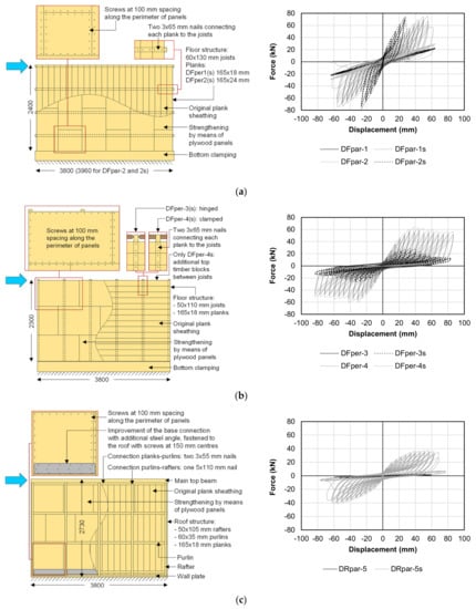
Figure 1.
Main characteristics and cyclic in-plane response of the timber diaphragms; floors tested parallel (a) and perpendicular to the joists (b) and roof pitch (c). More details on the retrofitting technique can be found in References [37,38].
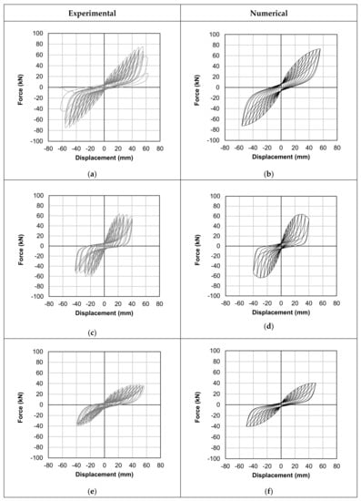
Figure 2.
Validation of the macro-element modeling strategy for timber diaphragms with the user-supplied subroutine based on the formulated analytical model [38,41]: (a) experimental and (b) numerical responses of a sample tested parallel to the joists; (c) experimental and (d) numerical responses of a sample tested perpendicular to the joists; (e) experimental and (f) numerical responses of a sample representing a roof pitch.
Section 2 provides an overview of the examined configurations of the case–study buildings, as well as the methodology followed for analyzing their seismic response and quantifying the dissipative role of the timber diaphragms. In Section 3, the results of the time–history analyses are reported in detail, and the performance of the case–study buildings is examined. Subsequently, Section 4 discusses these outcomes, with a specific focus on the role of the (retrofitted) floors. Finally, the conclusions of this study are reported in Section 5.
2. Analyzed URM Buildings Configurations and Adopted Methodology
2.1. Overview of the Case–Study Buildings and Main Properties
In order to prove the dissipative, beneficial effects of efficiently retrofitted timber diaphragms on the seismic performance of existing buildings, several configurations and multiple contexts and earthquake types were covered in the numerical analyses (Figure 3). Due to the aforementioned specific situation of the Groningen region, two case–study buildings presented characteristics typical of the Dutch context; therefore, both a detached house and a more monumental building located in that area were modeled. In order to generalize and extend the conclusions obtained for the Dutch framework, a third case–study building was considered—namely, an Italian country house typical of Po Valley and the Venetian Plain (Province of Padua).
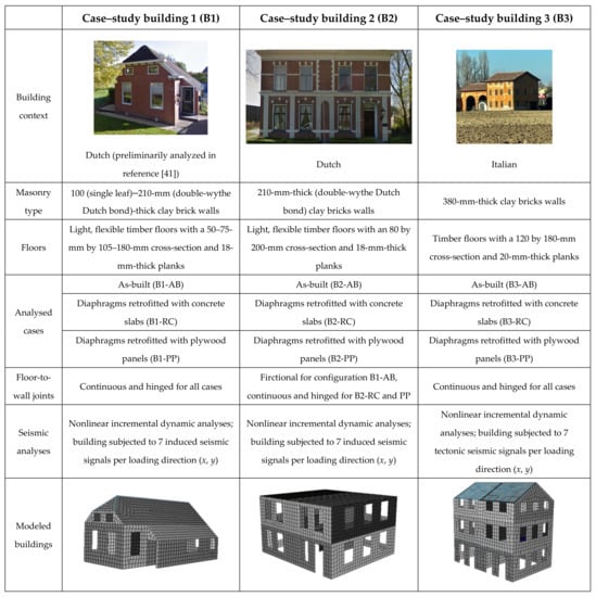
Figure 3.
Overview of the three analyzed case–study URM buildings and their configurations.
For all URM buildings, three configurations were considered: an as-built one with flexible timber diaphragms, a configuration having floors retrofitted with a concrete slab (widely applied until recently [1,2,3,4]), and a configuration featuring diaphragms strengthened with a plywood panel overlay, designed considering the optimization of the seismic capacity of the whole building. All case–study buildings were modeled in finite element software DIANA FEA [44], adopting the strategies presented in the following section.
2.2. Modeling Strategies
For all case–study buildings, the nonlinear seismic response of masonry was simulated by means of the Engineering Masonry Model [45], assigned to the eight-node flat shell elements representing the walls.
As-built timber floors were modeled with linear elastic, orthotropic, eight-node flat shell elements following the modeling strategy already presented and validated in Reference [41]; the properties of the shell elements were derived by considering separately the in-plane and out-of-plane properties of the floors. More specifically, the in-plane properties were represented by means of a (low) shear modulus Gxy derived from the equivalent shear stiffness (Gd = Gxy∙t, with t thickness of the sheathing [37,39,41]) of the diaphragms. The out-of-plane properties were determined through an equivalence in the flexural properties between the joists and the shell slab, defining an equivalent elastic modulus as Eeq = EtimberIjoists/Islab, with Etimber = 10,000 MPa. The moment of inertia of the joists Ijoists depends on their total number in the floor and their cross-section, whereas the moment of inertia of the equivalent slab Islab depends on its thickness (equal to that of the sheathing) and the length of its supported side. This implies that Eeq can result in very large values, because it represents a fictitious material concentrating the flexural properties of the joists within the small thickness of the shell elements. Then, similar to an actual timber-based material, the out-of-plane shear moduli were determined as Gxz = Gyz = Eeq/16 [41]. This modeling strategy involving equivalent properties had the advantage of representing the behaviors of the diaphragms under both out-of-plane (e.g., vertical or static) and in-plane (e.g., seismic) loads, using only shell elements. Furthermore, the seismic masses pertaining to the floors could also be modeled in a more realistic, distributed way, as was the case with the masonry.
Concrete slabs were modeled with linear elastic isotropic eight-node plates, featuring the material properties of reinforced concrete.
Diaphragms retrofitted with plywood panels were simulated by combining linear elastic, orthotropic, eight-node flat shell elements for their out-of-plane response and nonlinear macro-elements for their in-plane, dissipative response (Figure 4 and Figure 5), according to the modeling strategy reported in Reference [41]. The out-of-plane behavior was modeled in the same way as the as-built floors, yet considering the thickness of the slabs as the sum of that of the sheathing and that of the plywood panels [41]. Besides, the in-plane shear modulus Gxy of the shell elements was set to 0.1, since this type of response was modeled with macro-elements. These were composed of quadrilaterals of rigid truss elements surrounding two nonlinear diagonal truss elements, simulating the in-plane dissipative response of the floor (see Figure 4 and Figure 5 and Reference [41]). The diagonal elements had constitutive laws determined on the basis of the strength and stiffness of the retrofitted floors and the geometry of the macro-element mesh. More specifically, once the retrofitting intervention is designed and the strength and stiffness of the floor are known, in the model, the macro-element mesh can be arbitrarily chosen, and the load–slip response of the diagonal elements can be determined accordingly. In fact, the user-supplied subroutine for creating the constitutive law of the nonlinear diagonal trusses requires three input parameters [41]: the strain εmax at the peak stress σmax, the peak stress σmax itself, and the initial elastic modulus K0. With reference to Figure 5, starting from the whole floor deflection δ, the displacement u of a single truss is given by u = (δ cosα)/m, with the α angle between the truss and the loading direction and the m number of macro-elements rows parallel to the applied load in half of the floor (in the case of Figure 5, m = 2). The shear force F/2 is then subdivided among the s trusses in one macro-elements row and transformed into an axial force N on a single one with the equivalence N = F/(2scosα) [38,41]. From the knowledge of the geometrical relations for N and u, the initial stiffness of the diagonal trusses can also be calculated. For convenience, a unitary cross-section was adopted for the truss elements, so that the force and stress could be coincident in their values, whereas the strains (and εmax in particular) were calculated according to the length of the diagonal elements. For further details, the reader is referred to Reference [41], where a calculation and validation example is reported.
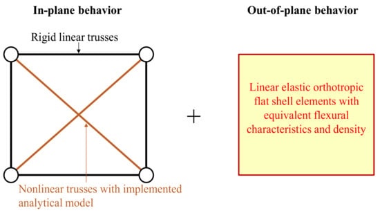
Figure 4.
Adopted strategy for modeling in-plane response (macro-elements featuring the implementation of the analytical model presented in Reference [38]) and out-of-plane behaviors (flexural equivalent shell elements) of timber diaphragms (Reprinted from Reference [41]).
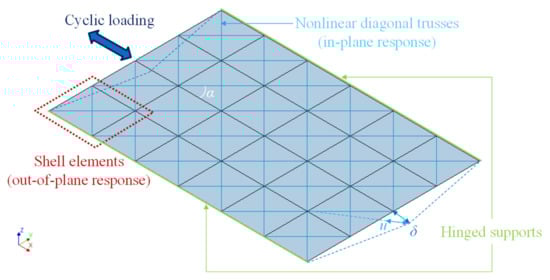
Figure 5.
Example of model of a retrofitted diaphragm created for validating the modeling strategy presented in Reference [41] (Reprinted from Reference [41]).
With reference to the last retrofitting method, in all the buildings, the diaphragms were designed to activate energy dissipation with a limited in-plane deflection while keeping the desired structural box behavior, similar to the preliminary analyses already presented in Reference [41]. More specifically, after evaluating the base shear of each building by means of a pushover analysis (considering rigid diaphragms), the horizontal loads at the floor and roof levels were estimated through the lateral force method; the strength of each diaphragm was thus designed in agreement with these floor shear forces, so that the in-plane strength of the wall could be brought into play. At the same time, since the dissipative contribution of the retrofitting method is activated through the in-plane deflection of the floors, this was limited, not to cause premature out-of-plane collapses in the masonry walls; therefore, the diaphragms were designed to reach their strength at an in-plane displacement equal to 2% of the out-of-plane walls’ height. This drift refers to the near-collapse limit state and is compatible with the wall thickness of each case–study building, since it always corresponds to a displacement value lower than half of the thickness itself [46,47]. An example of this design strategy was also presented in Reference [41]. On the basis of the aforementioned configurations and retrofitting methods, the following sections will provide geometrical and material properties separately for each case–study building.
2.3. Properties of Building B1
A detached house typical of the Groningen area was selected as the first case–study building (Figure 6). This URM low-rise house had a relatively simple structure, but some irregularities were present, such as the position and shape of the wall openings and the thickness of the walls, not constant along the height, with gables featuring a single-leaf wall (100 mm thick) instead of the ground floor double-wythe walls (210 mm thick). Besides, one more single-leaf wall was present, supporting one of the floors approximately at the midspan in correspondence to the staircase. This first building was already modeled and preliminarily analyzed in Reference [41].
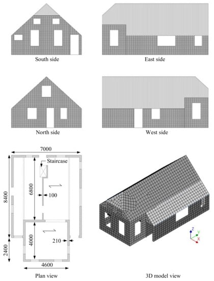
Figure 6.
Main properties and geometry of the first case–study building B1 (dimensions in mm).
The properties of masonry, reported in Table 1, were assumed to be the same for all the three analyzed configurations: B1-AB (as-built), B1-RC (diaphragms retrofitted with concrete slabs), and B1-PP (diaphragms retrofitted with plywood panels). The 300 × 300-mm shell elements with the implemented DIANA FEA (version 10.4) Engineering Masonry Model were used for modeling the masonry. While, for the walls, a density of 2000 kg/m3 was assumed, for the diaphragms, the density values included the self-weight of the structural elements; a dead load of 1.00 kN/m2 (accounting for further elements such as nonstructural walls, finishes, plants, and pipes); and 30% of the live load (0.3 × 1.75 kN/m2 for Dutch residential buildings [48]).

Table 1.
Properties of the shell elements simulating masonry walls in buildings B1 and B2. Reprinted from Reference [41].
Configuration B1-AB featured flexible diaphragms, having the following characteristics with reference to Figure 6:
- the 4.0 × 4.6-m floor presented 75 × 180-mm joists at 800-mm spacing;
- the 4.6 × 6.8-m floor had 60 × 160-mm joists arranged at 750-mm spacing;
- the roof presented 50 × 105-mm rafters at 900-mm spacing; on the rafters, purlins were arranged, supporting, in turn, the planks;
- all diaphragms featured 18-mm-thick planks.
These structural properties of the diaphragms were translated in the numerical model by following the aforementioned modeling strategy for as-built floors [41]; the diaphragms were modeled with linear elastic orthotropic shell elements whose properties are reported in Table 2. The elastic moduli of the diaphragms were derived by considering the (equivalent) in-plane and out-of-plane flexural properties of the planks or the joists [41]. Due to the already good floor-to-wall joints, a continuous, hinged connection at the floor supports was assumed for all cases; good interlocking among the masonry walls was considered as well.
Table 2.
Properties of the shell elements (thickness = 18 mm) representing the flexible diaphragms in configuration B1-AB. Reprinted from Reference [41].
In configuration B1-RC, featuring diaphragms retrofitted by casting a concrete slab on them, the floors were modeled with linear elastic isotropic shell elements, having the properties of structural reinforced concrete (Table 3). The thickness of the slab was 50 mm, as it would commonly be in practice [1,2,3,4].
Table 3.
Properties of the shell elements (thickness = 68 mm) representing the concrete slabs in configuration B1-RC. Reprinted from Reference [41].
For configuration B1-PP, having floors retrofitted with plywood panels, the modeling strategy presented and discussed in Reference [41] was adopted: linear elastic orthotropic shell elements simulated the out-of-plane response of the diaphragms, while macro-elements were used to represent their nonlinear, dissipative, in-plane response. The macro-elements featured a user-implemented subroutine for DIANA FEA, able to capture the pinching response of the floors, as presented in References [38,41]. Table 4 reports the properties of the macro- and shell elements simulating the retrofitted diaphragms. The strengthening interventions on the floors were designed on the basis of an estimated base shear of ≈450 kN; this corresponded to the following characteristics for the single diaphragms, on which the properties reported in Table 4 are based:
Table 4.
Properties of the shell elements (thickness = 36 mm) and macro-elements representing the diaphragms retrofitted with plywood panels in configuration B1-PP. Reprinted from Reference [41].
- the 4.0 × 4.6-m floor had a strength of 130 kN reached at 54-mm in-plane deflection and was meshed with 4 × 4 macro-elements;
- the 4.6 × 6.8-m floor had a strength of 200 kN reached at 60-mm in-plane deflection and was meshed with 4 × 6 macro-elements;
- each roof pitch had a strength of 150 kN reached at 40-mm in-plane deflection and was meshed with 3 × 8 macro-elements.
2.4. Properties of Building B2
As the second case–study structure, a larger building was chosen, having some monumental features and resembling the former post office building of Loppersum, NL (Figure 7). This URM building was overall quite regular and presented double-wythe clay brick masonry walls (210 mm thick). The properties of the masonry were assumed to be identical for all configurations and were the same as adopted for the first case–study building (Table 1); 400 × 400-mm shell elements were used. Similar to the previous case, for the walls, a density of 2000 kg/m3 was assumed, while, for the diaphragms, the density values included, once more, the self-weight of the structural elements, a dead load of 1.00 kN/m2, and 30% of the live load (0.3 × 1.75 kN/m2 for Dutch residential buildings [48]).
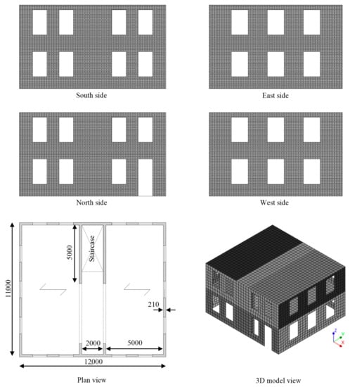
Figure 7.
Main properties and geometry of the second case–study building B2 (dimensions in mm).
The first- and second-floor diaphragms presented 80 × 200-mm joists at 500-mm spacing and 18 × 165-mm planks. These structural properties of the diaphragms were also, in this case, inserted into the numerical model by following the modeling strategy presented in Reference [41]; the linear elastic orthotropic shell elements simulating the as-built floors had the properties reported in Table 5. In the as-built state, the floors were connected at their supports, with a frictional interface (friction coefficient equal to 0.7) to simulate the mortar pocket joint.
Table 5.
Properties of the shell elements (thickness = 18 mm) representing the flexible diaphragms in configuration B2-AB.
In the configurations featuring diaphragms retrofitted by casting a concrete slab on them, the floors were modeled with linear elastic isotropic shell elements, having the properties of structural reinforced concrete (Table 6). The thickness of the slab was once more 50 mm, and a continuous, hinged connection to the walls was assumed after retrofitting.
Table 6.
Properties of the shell elements (thickness = 68 mm) representing the concrete slabs in configuration B2-RC.
For the configurations having floors retrofitted with plywood panels, the modeling strategy discussed in Reference [41] was also adopted for this case. Linear elastic orthotropic shell elements simulated the out-of-plane response of the floors, while the nonlinear macro-elements (1 × 1-m mesh), featuring the constitutive laws of the implemented user-supplied subroutine (Table 7), represented their in-plane behavior. The retrofitting interventions on the diaphragms were designed according to an estimated base shear of ≈650 kN, corresponding to a strength of 330 kN for both the first floor (reached at 70-mm in-plane deflection) and roof (reached at 140-mm in-plane deflection). Additionally, in this case, a continuous hinged connection at the floor supports was assumed.
Table 7.
Properties of the shell elements (thickness = 36 mm) and macro-elements representing the diaphragms retrofitted with plywood panels in configuration B2-PP.
2.5. Properties of Building B3
The third case–study building was selected to generalize even more the obtained results by considering another architectural context. Therefore, an Italian country house typical of Po Valley and located in the Province of Padua (Veneto) was chosen (Figure 8). This URM building had a regular structure and consisted of two units. In this case, the thickness of the walls was constant alongside the height and was equal to 380 mm, in agreement with past research studies on typical ancient Italian masonry [49,50]. Three configurations were once more studied: one represented the as-built house with flexible diaphragms (B3-AB); in the other two, the floors were retrofitted with plywood panels (B3-PP) or with a concrete slab (B3-RC).
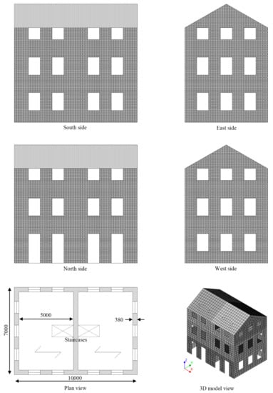
Figure 8.
Main properties and geometry of the third case–study building B3 (dimensions in mm).
The properties of the masonry reported in Table 8 were assumed to be the same for the three configurations; the adopted values were retrieved from References [49,50], where they were identified as material properties of a medium-quality masonry. The 400 × 400-mm shell elements were used for modeling the masonry. While, for the walls, a density of 2000 kg/m3 was assumed, for the diaphragms, the density values included the self-weight of the structural elements, a dead load of 1.00 kN/m2, and 30% of the live load (0.3 × 2.00 kN/m2 for Italian residential buildings [51]).
Table 8.
Properties of the shell elements representing masonry walls in building B3 based on the experimental studies reported in [49,50].
All timber diaphragms presented 120 × 180-mm joists at 500-mm spacing and 20 × 200-mm planks. The structural properties of the diaphragms were also, in this case, translated in the numerical model by following the modeling strategy for as-built floors previously described in Reference [41]. The as-built diaphragms were modeled with linear elastic orthotropic shell elements whose properties are reported in Table 9.
Table 9.
Properties of the shell elements (thickness = 18 mm) representing the flexible diaphragms in configuration B3-AB.
In the configurations featuring diaphragms retrofitted by casting a concrete slab on them, the floors were modeled with linear elastic isotropic shell elements having the properties of structural reinforced concrete (Table 10). The thickness of the slab was 50 mm.
Table 10.
Properties of the shell elements (thickness = 68 mm) representing the concrete slabs in configuration B3-RC.
For the configurations having floors retrofitted with plywood panels, the modeling strategy discussed in Reference [41] was also, for this case, adopted; besides the linear elastic orthotropic shell elements, nonlinear macro-elements (1 × 1-m mesh) were also present (Table 11), featuring the constitutive laws of the implemented user-supplied subroutine. The retrofitting interventions on the diaphragms were designed according to an estimated base shear of ≈1000 kN, corresponding to a strength of 230 kN for the first floor (reached at 60-mm in-plane deflection), 450 kN for the second floor (reached at 120-mm in-plane deflection), and 330 kN for the roof (reached at 180-mm in-plane deflection).
Table 11.
Properties of the shell elements (thickness = 36 mm) and macro-elements representing the diaphragms retrofitted with plywood panels in configurations B3-PP.
In all configurations, continuous, hinged connections at the floor supports were assumed, as, in the as-built case, adequate floor-to-wall joints were also present.
2.6. Methodology Adopted for the Seismic Analysis
2.6.1. Adopted Seismic Signals and Performance Indicators
For all case–study buildings, to retrieve a detailed picture of the seismic responses of the analyzed configurations, nonlinear incremental dynamic analyses were performed separately for the two plane directions: x and y (see Figure 6, Figure 7 and Figure 8); an intrinsic Rayleigh damping of 2% was considered to account for the viscous dissipation additional to the hysteretic energy activated by the cyclic response of the structural components. The first two case–study buildings, having Dutch features, were subjected to seven induced signals recorded in the Groningen area [52] and shown in Figure 9; for the third building, instead, seven recorded tectonic signals retrieved from REXEL version 3.5 [53] were used (Figure 10). Both signal types had a reference PGA of 0.17g.
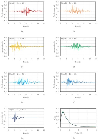
Figure 9.
Induced seismic signals (a–g) and their average response spectrum (h, depicted in black) [41,52] adopted for the numerical analyses on buildings B1 and B2.
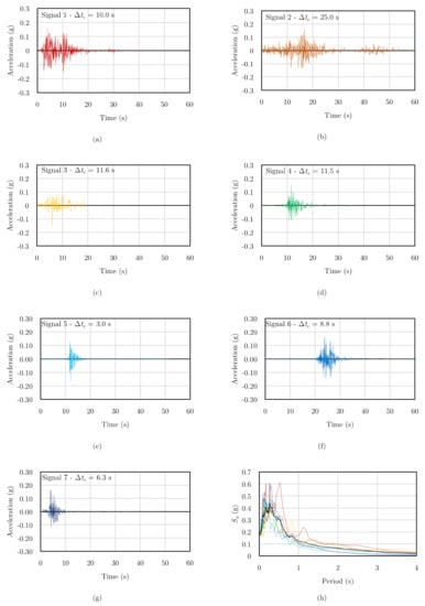
Figure 10.
Tectonic seismic signals (a–g) and their average response spectrum (h, depicted in black) [53] adopted for the numerical analyses on building B3.
The near-collapse seismic capacity of all the configurations was characterized by means of the following parameters:
- PGA at collapse, obtained when the in-plane shear or flexural failure of masonry piers is reached, when an out-of-plane failure occurs, or when the out-of-plane drift limit of 2.0% of the wall height is reached. As the fundamental periods of the analyzed buildings fell within the constant acceleration branch (plateau) of the response spectrum, if the spectral acceleration at the first mode period was also used as the performance indicator, this would approximately correspond to the PGA amplified by a factor of 2.5;
- Base shear-top floor (or roof) displacement responses, along with damage in terms of cracks opening in the masonry walls. The control nodes for all the curves corresponded to the center of mass of each building at the roof level, but also, other relevant reference nodes were considered for highlighting the role of the (retrofitted) floors in the seismic response of the analyzed buildings (Section 4);
- For the retrofitted cases, hysteretic energy was also considered, so that the dissipative contribution of the diaphragms strengthened with plywood panels in the analyzed buildings could be quantified in detail with respect to that of rigid concrete slabs.
Both PGA at collapse and hysteretic energy were adopted for assessing the energy dissipation activated by the wood-based retrofitting: PGA for quantifying the damping produced by the diaphragms and hysteretic energy for determining the behavior factor ranges, as presented in the following sections.
2.6.2. Equivalent Hysteretic Damping Ratio of the Floors Retrofitted with Plywood Panels
The values of PGA at collapse, besides identifying the seismic performance of the buildings, were also used to assess the additional damping induced by the dissipative diaphragms retrofitted with plywood panels. More specifically, in References [38,40,41], an equivalent damping ratio ξ of 15% was quantified for these diaphragms when designed for their pertaining floor seismic shear and a maximum in-plane deflection within the masonry drift limits. To assess whether this value was also activated in the analyzed URM buildings, the ratio was calculated between the average PGA at the collapse of the configurations having floors retrofitted with plywood panels and that of the cases with rigid diaphragms. In fact, if the floors were retrofitted with plywood panels, for a simplified modeling (e.g., a pushover analysis), they were assumed as stiff; their dissipative contribution could be taken into account by considering an overdamped spectrum reduced by factor η = [10/(5 + ξ)]1/2 [54]. Since η can also be estimated by the aforementioned PGAs ratio, the corresponding value of ξ can be retrieved.
2.6.3. Hysteretic Energy and Quantification of Behavior Factors
The use of hysteretic energy as the performance indicator allowed us to compare in terms of behavior factor values the results among the retrofitted configurations having rigid or dissipative diaphragms. More specifically, a procedure involving hysteretic energy and ductility was adopted for characterizing the retrofitted buildings. First of all, at least for sufficiently regular buildings that could be treated as (equivalent) single-degree-of-freedom (SDOF) systems, the hysteretic energy Ed that is dissipated during ground motion can be expressed as [55]:
In the former equation, ξ is the damping ratio of the system, m its mass, its (natural) frequency, the effective ground motion duration (in which 90% of the energy imparted to the system is dissipated [55]), Sv the spectral velocity, and () a factor denoting the mean value of the squares of the response displacement amplitudes [55]. Following Reference [55], two simplified equations were proposed to evaluate and (), depending on the (natural) period of the system Tn and on the seismic strong motion duration [55,56,57,58], reported for all the signals in Figure 9 and Figure 10:
It should be noticed that Equation (1) has the advantage of being damping-insensitive, because an increase in damping would correspond to a decrease in the pseudo-velocity and effective duration [55]. This is an advantage when predicting the hysteretic energy dissipated by the system, because this can be quantified by adopting directly the usual design response spectrum at ξ = 5% for a specific location [55]. Furthermore, since refers to 90% of the dissipated energy, the derived expression should be multiplied by a factor of 10/9 [55].
For buildings sufficiently regular in plan and elevation [54], the combination of Equations (1)–(3) enables the prediction of the dissipated hysteretic energy once the effective earthquake duration is known and an equivalent period for the system is defined, representing the evolution from elastic to plastic or the damaged state. The equivalent period Tn,eff was calculated according to FEMA 440 [59,60], as a function of the ductility μ of the system and its initial period Tn and independently of the type of hysteretic behavior.
- For 1 < μ < 4:
- For 4 ≤ μ ≤ 6.5:
- For μ > 6.5:
The ductility was evaluated by means of the equation that relates it to the behavior factor q [54]:
Thus, in this work, for the analyzed buildings with stiff diaphragms, the values of μ were referred to as the usual range of q = 1.5–2.5 [54], since the dissipation was, in this case, localized only in the masonry walls. Instead, to account for the additional dissipative contribution of the floors strengthened with plywood panels in comparison to rigid concrete diaphragms, the range could be increased and validated up to q = 2.5–3.5 for the configurations featuring the wood-based retrofitting. It should be noticed that both adopted ranges refer to very regular buildings featuring well-connected and homogeneous clay brick masonry. Yet, although the obtained results refer to almost ideal conditions for the existing buildings, they are still able to show the great potential and increased dissipation of the wood-based retrofitting technique with respect to rigid floors.
By fixing the behavior factor ranges, the corresponding ductility values allowed to calculate the relevant values, starting from the knowledge of the natural periods along the x and y directions, as determined by means of an eigenvalue analysis. Table 12 reports the natural periods of the as-built configurations and Table 13 the obtained values for the retrofitted configurations. Once was determined, this was used to predict the total hysteretic energy dissipated by the building, calculated with Equations (1)–(3) after determining the Sv from each signal’s response spectrum and inputting the pertaining strong motion duration . This procedure, novel for regular masonry buildings (but based on past analytical and empirical studies), allowed us to determine a range of hysteretic energy values, which were then compared to the single value of hysteretic energy computed by the numerical model. In this way, the use of both behavior factor ranges could be validated, as will be shown in the following sections.
Table 12.
Values of the natural period for the as-built configurations.
Table 13.
Values of the equivalent period for the retrofitted configurations as a function of the behavior factor range.
3. Results from the Analyses
3.1. Results in Terms of PGA, Base Shear-Top Roof Displacement Graphs, and Crack Pattern
The seismic performance of the three analyzed case–study buildings was firstly characterized in terms of PGA at collapse for both loading directions. Figure 11 shows this parameter for all the configurations, with both reference to each signal and on average.
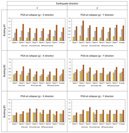
Figure 11.
PGA at collapse, displayed for each signal and on average, recorded for the three case–study buildings.
Starting from building B1, it can be noticed that as-built configuration B1-AB already collapsed at a low level of intensity (average PGA = 0.18 g in the weakest loading direction) due to the out-of-plane failure of (portion of) walls or gables. On the contrary, with floors stiffened with a concrete slab (configuration B1-RC), a great improvement in the capacity of the building was obtained (average PGA = 0.53 g in the weakest direction), mainly because of the enhanced box behavior, leading to the in-plane collapse of masonry walls. Yet, the best performance was retrieved with the plywood panel overlay in both loading directions (configuration B1-PP, average PGA = 0.81 g in the weakest direction); the box behavior and collapse of the in-plane walls were again activated but with the additional, beneficial contribution of the dissipative retrofitting.
Similar outcomes were observed for building B2 but with a better performance of the as-built configuration; despite causing, once more, the out-of-plane collapse of masonry walls, the average collapse PGA of 0.34 g in the weakest direction was now closer to that of retrofitted building B2-RC (0.46 g), mainly because the flexible floors increased the period of configuration B2-AB, resulting in lower accelerations transferred to the walls. Once more, configuration B2-PP provided the highest capacity among the three (0.73 g).
Building B3 confirmed these results but also showed that, interestingly, there was no radical improvement in the capacity between configurations B3-AB and B3-RC (average PGA ≈ 0.5 g for both). The massive size of the walls, with respect to the other two buildings, contributed to in-plane collapses even in the as-built cases, yet with extensive damage on the gables; thus, no premature out-of-plane collapse occurred. This seems to confirm a number of past studies [18,19,20,21,22,23,24], highlighting that as-built floors might already be sufficient to retrieve the total base shear of the building, provided that the diaphragms are well-connected to the walls, and the seismic shear transfer is fully enabled. However, if the floors are retrofitted in a dissipative way, as in configuration B3-PP, the seismic performance can be increased even further (PGA = 0.73 g) because of the additional damping effect.
Besides the PGA at collapse, for a more detailed characterization of the seismic response of the analyzed buildings, their base shear-top roof displacement curves and corresponding crack pattern and damage to the walls (in terms of the principal crack opening) are presented for all configurations in Figure 12, Figure 13 and Figure 14 in the weakest loading direction and with reference to seismic signal 1 as an example. It should be noticed that the principal crack opening contour was reported to show (through heavily cracked elements) which piers were the most damaged and their types of failure.
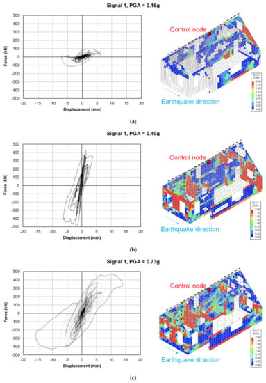
Figure 12.
Base shear vs. top roof displacement response and damage level in terms of the principal crack opening (Ecw1) for the three configurations: B1-AB (a), B1-RC (b), and B1-PP (c) at a near-collapse state.
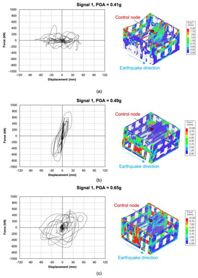
Figure 13.
Base shear vs. top roof displacement response and damage level in terms of the principal crack opening (Ecw1) for the three configurations: B2-AB (a), B2-RC (b), and B2-PP (c) at a near-collapse state.
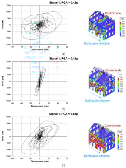
Figure 14.
Base shear vs. top roof displacement response and damage level in terms of the principal crack opening (Ecw1) for the three configurations: B3-AB (a), B3-RC (b), and B3-PP (c) at a near-collapse state.
Starting from building B1, configuration B1-AB showed a very flexible response: the floors underwent large displacements at an already limited signal amplitude, and the in-plane walls were not brought into play, with the exception of the very slender pier next to the staircase. Besides, the crack pattern (Figure 12a) showed a partial out-of-plane collapse of the 100-mm-thick central wall and of the north gable, probably due to torsional effects. A very different situation was noticeable in configuration B1-RC. In this case, the failure of the building was fully related to the in-plane walls, and a beneficial redistribution of the horizontal loads was achieved among the various walls; the force–displacement graph also confirms a typical shear-related in-plane failure of the masonry (Figure 12b). A hybrid response between the first two configurations was obtained with the floors retrofitted with plywood panels: a larger displacement capacity of the diaphragms, along with an in-plane failure of the walls, was noticeable (Figure 12c). The crack pattern was similar to that observed for the concrete slab configuration, with a slightly larger amount of damage in the out-of-plane walls because of the lower stiffness of the floors.
With regards to building B2, configuration B2-AB displayed a very flexible behavior, and the strength of in-plane walls was not involved. Besides, extensive damage of the out-of-plane walls was noticeable due to their out-of-phase oscillation induced by the poorly connected, flexible floors (Figure 13a). On the contrary, the strengthened floors were able to guarantee a better redistribution of the seismic loads among the walls, leading to an in-plane global failure. Additionally, while, with concrete slabs (Figure 13b), the collapse was mainly caused by the failure of the ground floor walls, with the floors strengthened with plywood panels (Figure 13c), the damage involved both story piers and spandrels, thus retrieving even more energy dissipation from the structure. In any case, the governing in-plane failure appeared to be shear diagonal cracking of the squat pier at the ground floor.
Building B3 showed an interesting difference compared to the previous case–study buildings: the in-plane strength of the wall was also brought into play in the as-built configuration, even if the gables experienced extensive out-of-plane damage at their bottom as well (Figure 14a). This means that, in this specific case, the thick walls, as well as the regularity and compactness of the structure, allowed the floors of configuration B3-AB to appropriately transfer shear loads because of the well-realized connections with masonry components. The fact that the stiffness of the as-built diaphragms could already be sufficient for the building to retrieve its whole base shear was confirmed by the similar capacity of configuration B3-RC (Figure 14b), although the stiff floors enhanced the box behavior of the building. An optimal performance was obtained with the designed light retrofitting intervention, which provided the floors with an increased energy dissipation more than an enhancement in stiffness, as can be noticed from the base shear–roof displacement curve (Figure 14c).
3.2. Results in Terms of Hysteretic Energy for the Retrofitted Configurations
As mentioned in Section 2.5, the retrofitted configurations of the three analyzed buildings were also characterized in terms of the dissipated hysteretic energy and behavior factor ranges. Figure 15 shows the comparison between the hysteretic energy recorded from the numerical models and that predicted as a function of the assumed behavior factor range for all configurations with rigid diaphragms and in both loading directions. As can be noticed, the usual behavior factor range of 1.5–2.5 commonly adopted for masonry structures appears to be appropriate and allows to predict, in most cases, conservatively the hysteretic energy that can be brought into play by the buildings. Yet, the fact that rigid diaphragms improve the box behavior of the buildings corresponds to a localization of the dissipated energy in the masonry piers.
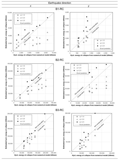
Figure 15.
Hysteretic energy from the numerical model and predicted with Equations (1)–(3) for the concrete slab retrofitting.
If, instead, the diaphragms are also able to activate energy dissipation, a remarkable beneficial effect on the buildings can be observed (Figure 16); floors retrofitted with plywood panels allow us to largely increase the hysteretic energy activated by the buildings when compared to the configurations with rigid diaphragms. This is related to the fact that the buildings with rigid floors showed stiff behaviors, especially in the y direction, linked to the presence of squat piers (see, for instance, B1-RC, which exhibited a very limited ductility). On the contrary, the increased displacement capacity and dissipation provided by the floors retrofitted with plywood panels, along with a higher fundamental period in both directions, allowed us to activate a much larger hysteretic energy and to subject the buildings to an increased amplitude of the seismic signals. This larger amplitude, in combination with the higher fundamental period compared to the configurations with rigid floors, is also consistent with a larger value of spectral velocity, on which the hysteretic energy depends through a quadratic relation, justifying its increased values for the configurations featuring the wood-based retrofitting.
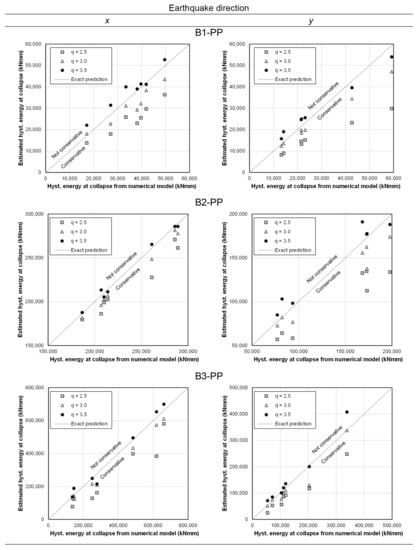
Figure 16.
Hysteretic energy from the numerical model and predicted with Equations (1)–(3) for the plywood panel retrofitting.
Figure 17 highlights how relevant the contribution of the dissipative floors can be in terms of their activated hysteretic energy, with respect to a retrofitting with rigid diaphragms. In all cases, the floors retrofitted with plywood panels are responsible for a significant increase in the energy that can be dissipated by the building. This also explains the capacity of these floors to provide an increase in the behavior factor range for the specific analyzed buildings, highlighting once more the great potential of well-designed wood-based retrofitting techniques. These outcomes, along with those of the preceding section, will now be discussed more in detail in Section 4, with specific reference to the role of (retrofitted) timber diaphragms.
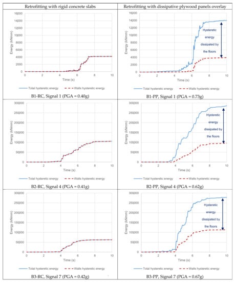
Figure 17.
Hysteretic energy vs. time for the retrofitted configurations at a near-collapse state. The dissipative role of the diaphragms retrofitted with plywood panels in comparison to the rigid concrete slabs is evident.
4. Discussion
The results of the three analyzed case–study buildings highlighted once more how the role of timber diaphragms in the seismic response of URM buildings can be crucial. The effect of the in-plane stiffness of the floors is firstly discussed, taking into account additional control nodes with respect to those selected in Figure 12, Figure 13 and Figure 14. Considering the out-of-plane seismic response of the front gable in building B1 (Figure 18), this can be regarded as one of its most vulnerable portions due to its reduced thickness (only 100 mm). The insufficient in-plane stiffness of the existing roof (Figure 18a) leads to a premature out-of-plane collapse of the gable, highlighted by the large, out-of-phase relative displacement between the two control nodes. This local collapse, if compared to the cases featuring stiffened diaphragms, occurs for a relatively low seismic acceleration, justifying the need of a retrofitting intervention. When the concrete slab retrofitting is applied (Figure 18b), the two control nodes display an identical displacement time–history, as expected with a rigid diaphragm system. The collapse of the building is, in this case, not related to the gable, as in the as-built situation, but to the in-plane failure of the squat walls along the earthquake direction. This same failure type was observed for configuration B3-PP (Figure 18c), which displayed a hybrid response: the floors retrofitted with plywood panels proved to be sufficiently stiff to activate the in-plane failure of the walls but also allowed for a limited out-of-plane displacement in the gable, activating energy dissipation in the strengthened roof.
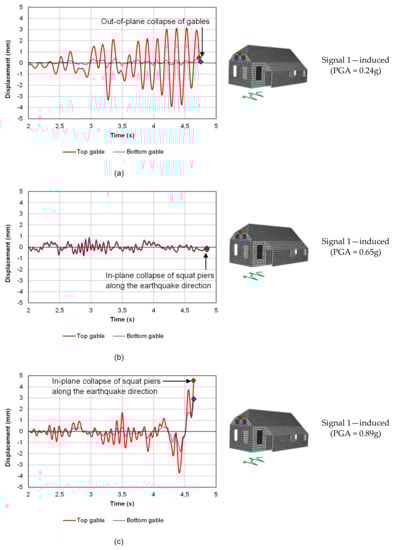
Figure 18.
Out-of-plane displacement time–histories of the front gable for configurations B1-AB (a), B1-RC (b), and B1-PP (c) at collapse.
The performed analyses also showed that the in-plane stiffness of the floors is responsible for how quickly the masonry piers are brought into play; this is exemplified in Figure 19 for building B2, taking into account the displacements of a control node on the roof and of one on the lateral walls. When considering the existing floors (Figure 19a), on the one hand, their low stiffness and deflection capacities could positively prevent the in-plane walls from being excessively solicited; on the other hand, their flexibility led to out-of-plane collapses and to an independent movement of each floor without retrieving the desired box behavior. With rigid concrete diaphragms (Figure 19b), the deflection of the floors is absent, and the diaphragms and walls undergo the same displacement. This solution guarantees the maximum redistribution of seismic shear forces and an excellent box behavior but directly brings the walls’ strength into play. When an optimized, dissipative retrofitting is chosen (Figure 19c), it is possible to link the displacement capacity of the diaphragms, enabling their energy dissipation potential, with an in-plane stiffness sufficient to redistribute seismic loads among the walls. Thus, similar to building B1-PP, the in-plane capacity of the piers is retrieved, but the damping effect of the floors can prevent this from occurring right at the beginning of the seismic signal, with an increase of the seismic capacity of the building.
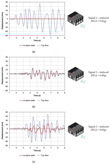
Figure 19.
Examples of top floor and in-plane wall displacement time–histories for configurations B2-AB (a), B2-RC (b), and B2-PP (c) at collapse.
The previously discussed results were again obtained in case–study B3 (Figure 20), subjected to tectonic earthquakes. Considering the control nodes at each floor level and at the top and bottom of the gable, configuration B3-AB (Figure 20a) showed that the existing flexible floors are sufficient to retrieve the in-plane strength of the walls because of the massive structure of the piers. However, the as-built floors cause extensive damage to the gables, where the largest relative displacements are recorded, and a dangerous out-of-phase movement of each floor level. In configuration B3-RC (Figure 20b), the observed displacements are all linked to the in-plane capacity of the walls because of the presence of rigid diaphragms. The response also shows an improved box behavior, but the PGA at collapse is interestingly the same as configuration B3-AB, as pointed out and discussed in Section 3.1. Finally, configuration B3-PP (Figure 20c) shows a combination of the two previous cases; as can be noticed, the presence of optimally designed retrofitted diaphragms induces an in-phase movement of the floor levels while reducing the dangerous relative displacement between the top and bottom of the gable and retrieves, at the same time, the in-plane capacity of the piers. This combination maximizes once more the hysteretic energy that can be activated and dissipated by the building, with a beneficial effect in its seismic response.
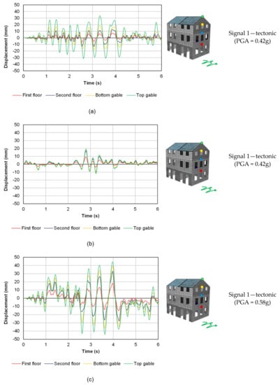
Figure 20.
Out-of-plane displacement time-histories of the front wall for configurations B3-AB (a), B3-RC (b), and B3-PP (c) at collapse.
The damping effect induced by the plywood panels retrofitting is also evident in Figure 21, comparing the response of the most solicited wall in building B1 when the diaphragms are retrofitted with concrete slabs or plywood panels; as can be noticed, under the same signal, when concrete slabs are present, the pier reaches its capacity after a shear diagonal failure; with plywood panels retrofitting, a damping effect on the wall is noticeable, and the maximum in-plane load for the pier is reached by further amplifying the signal to more than 35% compared to that applied to the B1-RC configuration. Yet, it is important to underline that, in order to be able to activate the dissipative potential of the floors, a dry screed made of loose materials (so that the diaphragms are not further stiffened by this component), as well as a continuous and resistant connection between the diaphragms and walls, has to be realized so that local collapses can be prevented and the box behavior can still be enabled [41].
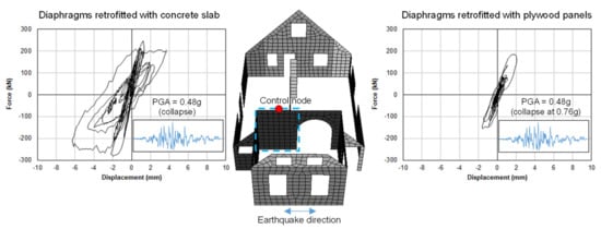
Figure 21.
Comparison between the in-plane response of the most solicited wall under the application of signal 4 in configurations B1-RC (left) and B1-PP (right). When the concrete slab brings the wall to the in-plane capacity, for the same PGA, the dissipative plywood panel retrofitting prevents the pier from reaching its ultimate strength, which is retrieved at 0.76g.
With reference to the increase in seismic capacity, in Reference [40], a value of equivalent hysteretic damping ratio ξ = 15% was determined for the diaphragms retrofitted with plywood panels. From the performed analyses, it appears that the difference in PGA at collapse between the configurations with stiff floors and those having dissipative diaphragms was, on average, approximately 30% (see Figure 11). This result thus confirms the obtained 15% equivalent damping ratio value; if the floors were retrofitted with plywood panels, and for a simplified modeling (e.g., a pushover analysis), they were assumed as stiff; their dissipative contribution could be taken into account by considering an overdamped spectrum reduced by the factor η = [10/(5 + ξ)]1/2 [54]. It is interesting to notice that η = 0.707 for ξ = 15%, a value suggesting that, when a dissipative retrofitting of the floors is designed, the demand response spectrum could indeed be reduced by approximately 30% in addition to the further nonlinear contributions of the in-plane masonry walls.
Furthermore, the largely increased hysteretic energy that can be activated in the URM buildings because of the presence of retrofitted, dissipative timber diaphragms was also linked to a higher behavior factor range of q = 2.5–3.5. It should be noticed that these values could be obtained considering very regular, low-rise buildings with homogeneous and well-connected masonry—thus, in almost ideal conditions when dealing with the seismic assessment and retrofitting of existing buildings; this was also confirmed by the large values of PGA obtained at collapse. Nevertheless, these same conditions of regularity and homogeneity of the masonry were applied for the configurations with concrete slabs. Therefore, by adopting the obtained behavior factor ranges as indicators for comparison, the increase in energy dissipation activated by the plywood panels retrofitting was tangible and could be predicted and validated. As a recommendation for further studies, since past shake table tests [61] highlighted that the use of the lower limit value of q = 1.5 should be preferred for buildings with rigid diaphragms, similar (full-scale) experiments could be performed to assess the potential increase in the behavior factor provided by an optimized, dissipative, wood-based strengthening of the timber floors in URM buildings.
5. Summary and Conclusions
In this work, the possibility of optimizing the seismic performance of URM buildings through the retrofitting of timber diaphragms was investigated, transforming them into dissipative structural components. Numerical time–history analyses were conducted on three case–study buildings, considering the as-built state with flexible floors, a retrofitting option with concrete slabs (and, thus, rigid floors), and a dissipative strengthening method consisting of plywood panels screwed on the existing diaphragms.
It was shown that, in order to optimize the seismic response of URM buildings, the retrofitting of timber diaphragms can be designed based on the pertaining floor seismic shear and masonry out-of-plane drift limits. In this way, the diaphragms can undergo the maximum deflection without causing out-of-plane collapse, activating at the same time the maximum base shear of the building: thus, the maximum energy dissipation can also be retrieved from the diaphragms. Yet, in order for the floors to efficiently transfer the seismic shear loads and deflect without causing local masonry collapses, the timber–masonry joints have to be effectively strengthened accordingly, as their role is paramount to efficiently redistribute the actions on the URM structure. Instead, if the diaphragms are too flexible, severe out-of-plane damage or collapses are observed, while, with rigid floors, the box behavior of the building is improved, but the dissipative contribution of the diaphragms cannot be activated.
The relevant, dissipative effect of well-retrofitted, optimized timber floors was quantified in terms of an equivalent hysteretic damping ratio of 15% additional to the dissipation already provided by the masonry walls. Besides, in the presence of optimally designed dissipative diaphragms, an increased behavior factor range of q = 2.5–3.5 was observed in comparison to the range of q = 1.5–2.5 for rigid floors. Throughout the analysis, this parameter was used to quantify the energy dissipation for the purpose of comparisons among the retrofitted configurations and refers to regular buildings featuring homogenous and well-connected clay brick masonry, as well as continuous floor-to-wall connections. Thus, it is expected that these values reflect almost ideal conditions when dealing with the seismic assessment and retrofitting of existing buildings; however, the obtained values still prove the beneficial effect of an optimized strengthening of timber diaphragms with respect to rigid floors. Hence, further (experimental) studies for validating the dissipative role of wood-based retrofitting techniques for timber floors in URM constructions are highly encouraged and recommended, so that a possible increase in the behavior factor can be assessed for real building prototypes as well.
The obtained results can further support a more aware seismic retrofitting of existing URM constructions, with specific references to the use of wood-based (dissipative) strengthening techniques as a more beneficial alternative to rigid concrete diaphragms, and can contribute to the research framework supporting the conservation of the architectural heritage of seismic-prone countries.
Author Contributions
Conceptualization, M.M. and G.R.; methodology, M.M.; software, M.M.; validation, M.M.; formal analysis, M.M. and G.R.; investigation, M.M. and G.R.; resources, G.R.; data curation, M.M.; writing—original draft preparation, M.M.; writing—review and editing, G.R.; visualization, M.M.; supervision, G.R.; project administration, G.R.; funding acquisition, G.R. All authors have read and agreed to the published version of the manuscript.
Funding
This research was funded by Nederlandse Aardolie Maatschappij, grant numbers C31B67 and CS2B04. The APC was funded by Delft University of Technology.
Institutional Review Board Statement
Not applicable.
Informed Consent Statement
Not applicable.
Conflicts of Interest
The authors declare no conflict of interest.
References
- Piazza, M.; Baldessari, C.; Tomasi, R. The Role of In-Plane Floor Stiffness in the Seismic Behaviour of Traditional Buildings. In Proceedings of the 14th World Conference on Earthquake Engineering, Beijing, China, 12–17 October 2008. [Google Scholar]
- Baldessari, C. In-Plane Behaviour of Differently Refurbished Timber Floors. Ph.D. Thesis, University of Trento, Trento, Italy, 2010. [Google Scholar]
- Piazza, M.; Turrini, G. Una tecnica di recupero statico dei solai in legno. In Recuperare; PEG Editrice: Milan, Italy, 1983; Volume 5. [Google Scholar]
- Corradi, M.; Speranzini, E.; Borri, A.; Vignoli, A. In-Plane Shear Reinforcement of Wood Beam Floors with FRP. Compos. Part B Eng. 2006, 37, 310–319. [Google Scholar] [CrossRef] [Green Version]
- Valluzzi, M.R.; Garbin, E.; Dalla Benetta, M.; Modena, C. Experimental Assessment and Modelling of In-Plane Behaviour of Timber Floors. In Proceedings of the 6th International Conference Structural Analysis of Historical Constructions, Bath, UK, 2–4 July 2008; pp. 755–762. [Google Scholar]
- Valluzzi, M.R.; Garbin, E.; Dalla Benetta, M.; Modena, C. In-Plane Strengthening of Timber Floors for the Seismic Improvement of Masonry Buildings. In Proceedings of the 11th World Conference on Timber Engineering, Riva del Garda, Italy, 20–24 June 2010. [Google Scholar]
- Branco, J.M.; Kekeliak, M.; Lourenço, P.B. In-Plane Stiffness of Timber Floors Strengthened with CLT. Eur. J. Wood Wood Prod. 2015, 73, 313–323. [Google Scholar] [CrossRef] [Green Version]
- Gubana, A.; Melotto, M. Experimental tests on wood-based in-plane strengthening solutions for the seismic retrofit of traditional timber floors. Constr. Build. Mater. 2018, 191, 290–299. [Google Scholar] [CrossRef]
- Peralta, D.F.; Bracci, M.J.; Hueste, M.B.D. Seismic Behavior of Wood Diaphragms in Pre-1950s Unreinforced Masonry Buildings. J. Struct. Eng. 2004, 130, 2040–2050. [Google Scholar] [CrossRef]
- Brignola, A.; Pampanin, S.; Podestà, S. Experimental Evaluation of the In-Plane Stiffness of Timber Diaphragms. Earthq. Spectra 2012, 28, 1–23. [Google Scholar] [CrossRef] [Green Version]
- Wilson, A.; Quenneville, P.J.H.; Ingham, J.M. In-Plane Orthotropic Behavior of Timber Floor Diaphragms in Unreinforced Masonry Buildings. J. Struct. Eng. 2014, 140, 04013038. [Google Scholar] [CrossRef]
- Giongo, I.; Dizhur, D.; Tomasi, R.; Ingham, J.M. In plane assessment of existing timber diaphragms in URM buildings via quasi static and dynamic in situ tests. Adv. Mater. Res. 2013, 778, 495–502. [Google Scholar] [CrossRef]
- Lin, T.-J.; LaFave, J.M. Experimental Structural Behavior of Wall-Diaphragm Connections for Older Masonry Buildings. Constr. Build. Mater. 2012, 26, 180–189. [Google Scholar] [CrossRef]
- Moreira, S.; Oliveira, D.V.; Ramos, L.F.; Lourenço, P.B.; Fernandes, R.P.; Guerreiro, J. Experimental study on the seismic behavior of masonry wall-to-floor connections. In Proceedings of the 15th World Conference on Earthquake Engineering, Lisbon, Portugal, 24–28 September 2012. [Google Scholar]
- Moreira, S.; Ramos, L.F.; Oliveira, D.V.; Lourenço, P.B.; Mateus, L. Developing a seismic retrofitting solution for wall-to-floor connections of URM with wood diaphragms. In Proceedings of the 9th International Masonry Conference, Guimarães, Portugal, 7–9 July 2014. [Google Scholar]
- Dizhur, D.; Giaretton, M.; Ingham, J.M. URM wall-to-diaphragm and timber joist connection testing. In Proceedings of the 10th International Masonry Conference, Milan, Italy, 9–11 July 2018. [Google Scholar]
- Gubana, A. State-of-the-Art Report on high reversible timber to timber strengthening interventions on wooden floors. Constr. Build. Mater. 2015, 97, 25–33. [Google Scholar] [CrossRef]
- Magenes, G.; Penna, A.; Galasco, A. A full-scale shaking table test on a two-storey stone masonry building. In Proceedings of the 14th European Conference on Earthquake Engineering, Ohrid, North Macedonia, 30 August–3 September 2010. [Google Scholar]
- Magenes, G.; Penna, A.; Rota, M.; Galasco, A.; Senaldi, I. Shaking table test of a full scale stone masonry building with stiffened floor and roof diaphragms. In Proceedings of the 15th World Conference on Earthquake Engineering, Lisbon, Portugal, 24–28 September 2012. [Google Scholar]
- Senaldi, I.; Magenes, G.; Penna, A.; Galasco, A.; Rota, M. The Effect of Stiffened Floor and Roof Diaphragms on the Experimental Seismic Response of a Full-Scale Unreinforced Stone Masonry Building. J. Earthq. Eng. 2014, 18, 407–443. [Google Scholar] [CrossRef]
- Scotta, R.; Trutalli, D.; Marchi, L.; Pozza, L. Effects of in-plane strengthening of timber floors in the seismic response of existing masonry buildings. In Proceedings of the World Conference on Timber Engineering, Vienna, Austria, 22–25 August 2016. [Google Scholar]
- Scotta, R.; Trutalli, D.; Marchi, L.; Pozza, L.; Mirra, M. Seismic response of masonry buildings with alternative techniques for in-plane strengthening of timber floors. Revista Portuguesa de Engenharia de Estruturas 2017, 4, 47–58. [Google Scholar]
- Scotta, R.; Trutalli, D.; Marchi, L.; Pozza, L. Seismic performance of URM buildings with in-plane non-stiffened and stiffened timber floors. Eng. Struct. 2018, 167, 683–694. [Google Scholar] [CrossRef]
- Trutalli, D.; Marchi, L.; Scotta, R.; Pozza, L. Seismic capacity of irregular unreinforced masonry buildings with timber floors. Proc. Inst. Civ. Eng.-Struct. Build. 2020, 174, 473–490. [Google Scholar] [CrossRef]
- Decanini, L.; De Sortis, A.; Goretti, A.; Langenbach, R.; Mollaioli, F.; Rasulo, A. Performance of Masonry Buildings during the 2002 Molise, Italy, Earthquake. Earthq. Spectra 2004, 20, S191–S220. [Google Scholar] [CrossRef]
- Valluzzi, M.R. On the vulnerability of historical masonry structures: Analysis and mitigation. Mater. Struct. 2007, 40, 723–743. [Google Scholar] [CrossRef]
- Modena, C.; Valluzzi, M.R.; da Porto, F.; Casarin, F. Structural Aspects of the Conservation of Historic Masonry Constructions in Seismic Areas: Remedial Measures and Emergency Actions. Int. J. Archit. Herit. 2011, 5, 539–558. [Google Scholar] [CrossRef]
- Saretta, Y.; Sbrogiò, L.; Valluzzi, M.R. Seismic response of masonry buildings in historical centres struck by the 2016 Central Italy earthquake. Calibration of a vulnerability model for strengthened conditions. Constr. Build. Mater. 2021, 299, 123911. [Google Scholar] [CrossRef]
- Vlachakis, G.; Vlachaki, E.; Lourenço, P.B. Learning from failure: Damage and failure of masonry structures, after the 2017 Lesvos earthquake (Greece). Eng. Fail. Anal. 2020, 117, 104803. [Google Scholar] [CrossRef]
- Stepinac, M.; Lourenço, P.B.; Atalić, J.; Kišiček, T.; Uroš, M.; Baniček, M.; Šavor Novak, M. Damage classification of residential buildings in historical downtown after the ML5.5 earthquake in Zagreb, Croatia in 2020. Int. J. Disaster Risk Reduct. 2021, 56, 102140. [Google Scholar] [CrossRef]
- Bilgin, H.; Shkodrani, N.; Hysenlliu, M.; Baytan Ozmen, H.; Isik, E.; Harirchian, E. Damage and performance evaluation of masonry buildings constructed in 1970s during the 2019 Albania earthquakes. Eng. Fail. Anal. 2021, 131, 105824. [Google Scholar] [CrossRef]
- van Eck, T.; Goutbeek, F.; Haak, H.; Dost, B. Seismic hazard due to small-magnitude, shallow-source, induced earthquakes in The Netherlands. Eng. Geol. 2006, 87, 105–121. [Google Scholar] [CrossRef]
- ARUP. Groningen 2013—Implementation Study; Document REP/229746/IS001, Issue Rev A, 29 November 2013; ARUP: Amsterdam, The Netherlands, 2013. [Google Scholar]
- Messali, F.; Ravenshorst, G.J.P.; Esposito, R.; Rots, J.G. Large-scale testing program for the seismic characterization of Dutch masonry walls. In Proceedings of the 16th World Conference on Earthquake Engineering (WCEE), Santiago, Chile, 9–13 January 2017. [Google Scholar]
- Jafari, S.; Rots, J.G.; Esposito, R.; Messali, F. Characterizing the Material Properties of Dutch Unreinforced Masonry. Procedia Eng. 2017, 193, 250–257. [Google Scholar] [CrossRef]
- Messali, F.; Esposito, R.; Ravenshorst, G.J.P.; Rots, J.G. Experimental investigation of the in-plane cyclic behaviour of calcium silicate brick masonry walls. Bull. Earthq. Eng. 2020, 18, 3963–3994. [Google Scholar] [CrossRef] [Green Version]
- Mirra, M.; Ravenshorst, G.J.P.; van de Kuilen, J.W.G. Experimental and analytical evaluation of the in-plane behaviour of as-built and strengthened traditional wooden floors. Eng. Struct. 2020, 211, 10432. [Google Scholar] [CrossRef]
- Mirra, M.; Ravenshorst, G.J.P.; de Vries, P.A.; van de Kuilen, J.W.G. An analytical model describing the in-plane behaviour of timber diaphragms strengthened with plywood panels. Eng. Struct. 2021, 235, 112128. [Google Scholar] [CrossRef]
- Mirra, M.; Ravenshorst, G.; van de Kuilen, J.-W. Comparing In-Plane Equivalent Shear Stiffness of Timber Diaphragms Retrofitted with Light and Reversible Wood-Based Techniques. Pract. Period. Struct. Des. Constr. 2021, 26, 04021031. [Google Scholar] [CrossRef]
- Mirra, M.; Ravenshorst, G.J.P.; van de Kuilen, J.W.G. Dissipative properties of timber diaphragms strengthened with plywood panels. In Proceedings of the World Conference on Timber Engineering, Santiago, Chile, 9–12 August 2021. [Google Scholar]
- Mirra, M.; Sousamli, M.; Longo, M.; Ravenshorst, G.J.P. Analytical and numerical modelling of the in-plane response of timber diaphragms strengthened with plywood panels. In Proceedings of the 8th ECCOMAS Thematic Conference on Computational Methods in Structural Dynamics and Earthquakes Engineering, Athens, Greece, 28–30 June 2021. [Google Scholar]
- Lagomarsino, S.; Penna, A.; Galasco, A.; Cattari, S. TREMURI program: An equivalent frame model for the nonlinear seismic analysis of masonry buildings. Eng. Struct. 2013, 56, 1787–1799. [Google Scholar] [CrossRef]
- Giongo, I.; Piazza, M.; Tomasi, R. Pushover analysis of traditional masonry buildings: Influence of refurbished timber-floors stiffness. In Proceedings of the SHATIS’11 International Conference on Structural Health Assessment of Timber Structures, Lisbon, Portugal, 16–17 June 2011. [Google Scholar]
- Ferreira, D. (Ed.) DIANA—Finite Element Analysis. User’s Manual Release 10.4; DIANA FEA BV: Delft, The Netherlands, 2020. [Google Scholar]
- Schreppers, G.M.A.; Garofano, A.; Messali, F.; Rots, J.G. DIANA Validation Report for Masonry Modelling; DIANA FEA BV: Delft, The Netherlands; Delft University of Technology: Delft, The Netherlands, 2017. [Google Scholar]
- Giongo, I.; Wilson, A.; Dizhur, D.; Derakhshan, H.; Tomasi, R.; Griffith, M.C.; Quenneville, P.; Ingham, J.M. Detailed seismic assessment and improvement procedure for vintage flexible timber diaphragms. Bull. N. Z. Soc. Earthq. Eng. 2014, 47, 97–118. [Google Scholar] [CrossRef] [Green Version]
- NZS 1170 Structural Design Actions Part 5 Earthquake Actions; Standards New Zealand: Wellington, New Zealand, 2004.
- NEN-EN 1990:2002+A1:2019+NB:2019. In Grondslagen Van Het Constructief Ontwerp (Dutch National Version of Eurocode 0); Nederlands Normalisatie-Instituut (NEN): Delft, The Netherlands, 2002.
- Magenes, G.; Calvi, G.M. Cyclic Behaviour of Brick Masonry Walls. In Proceedings of the 10th World Conference on Earthquake Engineering, Madrid, Spain, 19–24 July 1992. [Google Scholar]
- Magenes, G.; Calvi, G.M. In-plane seismic response of brick masonry walls. Earthq. Eng. Struct. Dyn. 1997, 26, 1091–1112. [Google Scholar] [CrossRef]
- NTC 2018. Norme Tecniche per le Costruzioni (Italian Regulations for Structural Design); Ministry of Infrastructures and Transports: Rome, Italy, 2018.
- Nederlands Normalisatie-Instituut (NEN). Webtool NPR 9998. 2021. Available online: https://seismischekrachten.nen.nl (accessed on 27 November 2021).
- Iervolino, I.; Galasso, C.; Cosenza, E. REXEL: Computer aided record selection for code-based seismic structural analysis. Bull. Earthq. Eng. 2009, 8, 339–362. [Google Scholar] [CrossRef]
- EN 1998-1:2004. Eurocode 8: Design of Structures for Earthquake Resistance—Part 1: General Rules, Seismic Actions and Rules for Buildings; European Committee for Standardization: Brussels, Belgium, 2004.
- Nurtuǧ, A.; Sucuoǧlu, H. Prediction of seismic energy dissipation in SDOF systems. Earthq. Eng. Struct. Dyn. 1995, 24, 1215–1223. [Google Scholar] [CrossRef]
- Trifunac, M.D.; Brady, A.G. A study on the duration of strong earthquake ground motion. Bull. Seismol. Soc. Am. 1975, 65, 581–626. [Google Scholar]
- Bommer, J.J.; Martínez-Pereira, A. The effective duration of earthquake strong motion. J. Earthq. Eng. 1999, 3, 127–172. [Google Scholar] [CrossRef]
- Bommer, J.J.; Magenes, G.; Hancock, J.; Penazzo, P. The influence of strong-motion duration on the seismic response of masonry structures. Bull. Earthq. Eng. 2004, 2, 1–26. [Google Scholar] [CrossRef]
- Comartin, C.D.; Aschheim, M.; Guyader, A.; Hamburger, R.; Hanson, R.; Holmes, W.; Iwan, W.; Mahoney, M.; Miranda, E.; Mohele, J.; et al. A summary of FEMA 440: Improvement of nonlinear static seismic analysis procedures. In Proceedings of the 13th World Conference on Earthquake Engineering, Vancouver, BC, Canada, 1–6 August 2004. [Google Scholar]
- FEMA 440. Improvement of Nonlinear Static Seismic Analysis Procedures; Federal Emergency Management Agency: Washington, DC, USA, 2005.
- Tomaževič, M.; Bosiljkov, V.; Weiss, P. Structural Behaviour Factor for Masonry Structures. In Proceedings of the 13th World Conference on Earthquake Engineering, Vancouver, BC, Canada, 1–6 August 2004. [Google Scholar]
Publisher’s Note: MDPI stays neutral with regard to jurisdictional claims in published maps and institutional affiliations. |
© 2021 by the authors. Licensee MDPI, Basel, Switzerland. This article is an open access article distributed under the terms and conditions of the Creative Commons Attribution (CC BY) license (https://creativecommons.org/licenses/by/4.0/).