Abstract
TiC/316L stainless steel (316Lss) metal matrix composite parts have been formed using selective laser melting (SLM). In this study, we have investigated the influence of the TiC mass fraction on the microstructure evolution, microhardness, friction properties, wear properties, and corrosion resistance of the TiC/316Lss composites. The results show that the microhardness increased by the addition of the TiC mass fraction. In terms of friction and wear properties, the corrosion resistance initially increased, and then decreased. Compared with the pure 316Lss (298.3 HV0.2), the microhardness of the TiC/316Lss composites, which were formed with 2 wt% TiC, was raised to 335.2 HV0.2, which was a 12.4% increase, while the average friction coefficient was 0.123. The reason for this is that the addition of TiC can effectively refine the cell size, and as the TiC content increases, the refinement effect is more obvious. During the melting process, TiC particles act as nucleation centres, hindering the growth of crystal cells, promoting the formation of the austenite phase, and forming fine equiaxed structures, which increases the strength. However, excessive TiC particles aggravate the spheroidisation during the process of SLM, leading to increased defects, as well as a decrease in density and corrosion resistance.
1. Introduction
The technology of selective laser melting (SLM) is the latest development of additive manufacturing. This technology can realize the rapid forming of complex structural parts, greatly reduce the processing procedures, shorten the processing cycle, and reduce the development costs and risks. At present, it has been widely used in biomedical parts, radiator parts, ultra-light structural parts, and micro-devices, as well as other fields [,,,,]. In recent years, the strength and hardness of ordinary pure 316L stainless steel (316Lss) have been unable to meet some of the requirements of national defence and the nuclear power industries, such as those for parts that bear a heavy load and have high wear resistance. Metal matrix composites have many advantages, such as thermal conductivity, electrical conductivity, wear resistance, a small coefficient of thermal expansion, good damping, non-moisture absorption, non-ageing, and being pollution-free. They are widely used in aviation, nuclear power, national defence, and other fields []. At present, a large number of related studies have shown that the mechanical properties of 316Lss can be improved by adding ceramic particles [,,]. The most commonly used reinforcing phases include SiC, TiC, TiB2, TiCN, and so on. Among them, TiC is the most commonly used reinforcing phase in Al–Mg alloys and Fe-based alloys. In addition, the ceramic reinforcing phase TiC particles have high hardness, a high melting temperature, thermodynamic stability, and good wettability with 316L stainless steel without undergoing phase transformation. 316Lss alloys are widely used in industry due to their good ductility and corrosion resistance. However, their limited strength and wear resistance at high temperatures hinders their wide applicability []. This problem may be ameliorated by the addition of hard TiC ceramic particles to the 316Lss alloy matrix. Due to its low density, high hardness, and good thermal stability, the wear resistance and corrosion resistance of the composite material can be significantly improved by the TiC [].
Traditional processes such as casting or sintering are also used to make TiC–316L composites [], but it is difficult to solve the uneven dispersion of reinforcing particles []. Compared with the traditional moulding method [], SLM can produce materials with finer cells, while cell refinement can improve the strength and hardness of materials without loss of plasticity [,,,]. Therefore, many domestic and foreign scholars have conducted a great deal of research on SLM-formed 316Lss. Kong et al. investigated the microstructure and corrosion behaviour of 316Lss that were fabricated using SLM []. Suryawanshi et al. measured the tensile, fracture, and fatigue crack growth properties of 316Lss produced using the SLM technique and compared them with those of conventionally manufactured (CM) austenitic stainless steels []. Lou et al. studied the stress corrosion crack propagation behaviour of laser-assisted 316Lss in high-temperature water []. Moreover, Tucho et al. studied the effect of porosity level and technological parameters on the microstructure and hardness of 316Lss parts formed using SLM [].
In addition, the performance of SLM-formed 316Lss was improved after adding a ceramic reinforced phase. Stašić et al. reported the effect of adding NiB on the microstructure of SLM-formed 316Lss parts. It was confirmed that the addition of NiB could better improve the surface quality and mechanical properties of 316L stainless steel parts []. Yadollahi et al. demonstrated that the microstructure and friction and wear properties of titanium and tin coatings are improved with the increase of plasma nitriding temperature and laser power []. Almangour et al. reported the effect of the addition of TiB2 on the microstructure and mechanical properties of SLM-formed nanocomposites; TiB2/316L nanocomposites have a higher microhardness and yield strength, lower friction coefficient, and lower wear rate than SLM-processed 316Lss samples []. Song et al. clarified that adding SiC to an Fe matrix results in a significant increase in local melt instability, viscosity, and tensile strength []. Almangour et al. reported that the mechanical and tribological properties of 316Lss nanocomposites are gradually improved with the increase of TiC and TiB2 volume fractions []. According to previous studies, the addition of the reinforcing phase can improve the mechanical properties. However, there are few studies on the formation of TiC-reinforced 316Lss composites formed by SLM.
In this study, TiC/316Lss composites were formed by SLM. The influence of the TiC mass fraction on the microstructure evolution, microhardness, friction properties, wear properties, and corrosion resistance of the TiC/316Lss composites are discussed, and the mechanism of the TiC-reinforced material performance was also investigated.
2. Experimental Procedures
2.1. Powder Preparation
In this study, experiments were carried out in an argon atmosphere with 316Lss spherical powder with the size of 45 μm. As shown in Figure 1a, the average particle size of TiC powder is between 2 μm and 5 μm (Figure 1b), as raw material. Three different TiC/316L composites containing 0 wt%, 2 wt% and 4 wt% TiC particles were prepared by milling TiC and 316Lss powders in a Pulverisette 4 ball mill (Fritsch GmbH, Germany). The grinding process was carried out in an Ar protective atmosphere. The ball was stainless steel. After milling for eight hours, the TiC particles corresponding to the enhanced concentration of 2 wt% and 4 wt% TiC were evenly attached to the 316Lss, which made the TiC/316Lss composite powders have excellent fluidity (Figure 1c,d); the chemical composition of the experimental 316Lss powder is shown in Table 1.
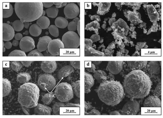
Figure 1.
SEM images of (a) pure 316L, (b) pure TiC, (c) 316L with 2 wt% TiC, (d) 316L with 4 wt% TiC.

Table 1.
The chemical composition of 316L stainless steel (wt%).
2.2. SLM Process
All of the samples were made using an SLM system (Renishaw AM 250, Renishaw, London, UK), which was equipped with a YLR-400 fibre laser that was conducted under Ar gas protection. The focused beam diameter was 70 μm. Samples were produced with a scanning speed (v) of 1200 mm/s, a laser power (P) of 200 W, a hatch spacing of 60 μm (h) (the distance between two adjacent scan vectors), and a layer thickness of 30 μm (t). Figure 2 shows a schematic diagram of the printing process. An alternate-hatching scanning pattern was applied, and the scanning direction rotation was 90° between each layer, as shown in Figure 3. Cube specimens with a size of 10 × 10 × 10 mm were manufactured. This parameter set was determined to obtain high-quality TiC/316Lss products.
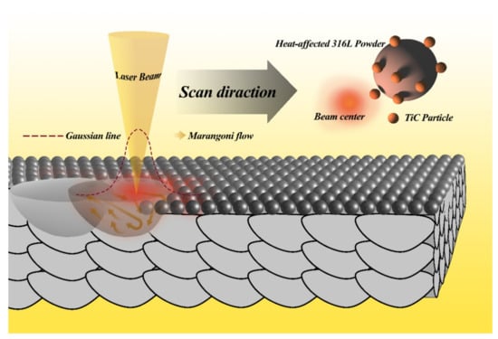
Figure 2.
Schematic of the laminated layerwise additive manufacturing model.
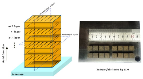
Figure 3.
Selective laser melting (SLM) process and 316L stainless steel (316Lss) fabricated by SLM.
2.3. Microstructural Observation
The sample was observed using microscopy. The following metallographic preparations are required for all samples before structural examination: grinding on SiC grinding papers up to a fine 2400-grit size, and polishing using silicon carbide papers (#100–#2500) and one-µm diamond suspension. To reveal the microstructure, samples were etched using Marble’s reagent for 10 seconds. The microstructures of the samples formed by the SLM were analysed using a scanning electron microscope (SEM) (Zeiss Ultra 55, Carl Zeiss Microscopy, Jena, Germany) equipped with an energy-dispersive X-ray spectral (EDS) analyser. Phase analysis using X-ray diffraction (XRD; X’Pert, PANalytical B.V., Almelo, The Netherlands) was conducted, and the scattering angle range of 2θ was 35°–100° under 5°/min continuous scanning mode. In addition, transmission electron microscopy (TEM) observations were performed using field-emission-gun (FEG) Tecnai G2 20 microscope (FEI, Hillsboro, OR, USA).
2.4. Mechanical and Wear Behaviours
The microhardness of the samples with different TiC contents was tested by TMHVS-1000 (China). Samples were kept under load for 15 s under pressure of 4.09N. A total of 15 indentations were made per cube, and the measured hardness was determined on one sample for a condition. Dry wear tests were performed on the samples formed by SLM using a tribometer at room temperature at a load of 200 g, a friction time of 30 min, a friction length of five mm, and a friction frequency of 100 mm/min. Each sample was measured three times, and then the average value was selected as the experimental data.
Finally, corrosion experiments were conducted, and the exposed surface area was 0.5 cm × 0.1 cm. The reference electrode that was used was a standard saturated calomel electrode, the auxiliary electrode was a platinum electrode, and the working electrode was the sample. The corrosion solution was 3.5 wt% NaCl, and the corrosion resistance of TiC/316L composites was quantitatively analysed from the Tafel curve.
3. Results and Discussion
Figure 4; Figure 5 show the XRD data of the composite powders and the composites formed by SLM with different content of TiC particles, respectively. The XRD data of composite powders in Figure 4 show that the intensity of TiC diffraction peaks increases with the increasing of the content of TiC. The XRD data of the composite sample shown in Figure 5 also show that with the increasing content of TiC, only the diffraction peaks of austenite gamma-Fe and TiC appear, but no other phase exists. Comparing these two results, it can be found that the strong diffraction peak of the composite material is obviously higher than that of the composite powder, and with the increase of TiC content, the cell is obviously refined [,,]. The reason for this phenomenon is that the SLM process is a process of rapid melting and solidification, and the cell is too late to grow. In addition, compared with the diffraction peaks of Figure 5a–c, it can be found that the peaks of the samples that have added TiC increases obviously; with the increase of TiC content, the cell size of the samples becomes finer.
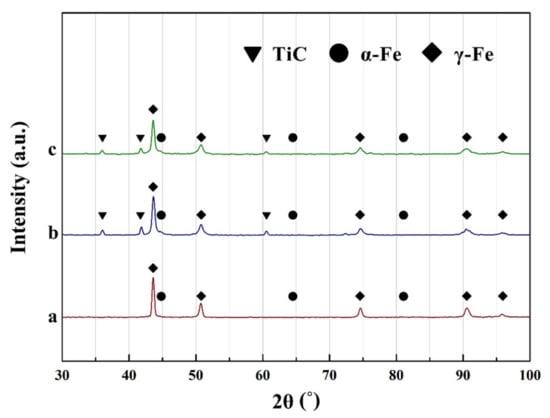
Figure 4.
X-ray diffraction (XRD) data of TiC-reinforced composite powders with mass fractions of (a) 0% TiC, (b) 2 wt% TiC, and (c) 4 wt% TiC.
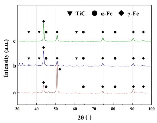
Figure 5.
XRD data of the TiC/316Lss composites formed by SLM reinforced with (a) 0 wt% TiC, (b) 2 wt% TiC, and (c) 4 wt% TiC.
Figure 6 shows the microstructures and morphologies of SLM-formed TiC/316Lss metal matrix composites after adding different proportions of TiC. It can be seen from the figure that the forming parts with three different proportions of TiC achieved a good forming effect, the boundary of the molten pool was obvious, the scale structure was formed, and the metallurgical bonding was good. Figure 6a, shows the microstructure of pure 316Lss without adding the TiC particles. The microstructure in the molten pool was subcellular dendrite with different sizes. There was a clear transition zone between the two, which preferentially grows towards the centre of the molten pool (Figure 6a). In the overlap area of adjacent scan lines, the average cell size was one μm, and there was an obvious steering cell. Figure 6c,d shows the microstructure morphology of the parts formed by adding 2 wt% TiC, and the TiC particles are uniformly distributed. The microstructure in the molten pool was mainly composed of a cell-like substructure with epitaxy growth characteristics. The average size of cell-like dendrites at the boundary of the molten pool was 0.75 μm. Equiaxed dendrites tended to grow towards the centre of the molten pool, and there was no obvious transition zone. Only a few columnar crystals appeared due to the remelting effect of the next layer on the upper layer, and the orientation of the crystals was different, illustrating the characteristics of epitaxy growth. Figure 6e,f shows the microstructures and morphologies of the parts formed by adding 4 wt% TiC; the cell size decreased obviously, and the average size was 0.43 μm. The reason for this is that with the increasing of the TiC, the cell size decreases obviously; then, the cell boundary increases due to the refinement of cell size, and more cell boundaries hinder the movement and propagation of dislocations, thus increasing the strength. In addition, with the increasing of the TiC, the possibility of aggregation of fine TiC particles at cell boundaries is greater. The aggregation of fine hard particles often leads to the formation of voids and the deterioration of interface bonding. The relative density was measured using the Archimedes method, and the results show that the relative density of samples with different TiC contents (0%, 2%, and 4%) was 95.8%, 93.2%, and 92.4%, respectively. Second, the thermal expansion coefficient of TiC (7.74 × 10⁻⁶/K) is quite different from that of 316Lss (17.3 × 10⁻⁶/K) [,]. The addition of TiC particles increased the dislocation density, hindered the volume change of the 316L matrix during melting and solidification, and further improved the properties of the metal matrix composites. There are two reasons for the cell refinement caused by TiC. First, TiC particles act as a nucleation centre in the molten pool, the formation of the austenite phase is promoted, and a fine equiaxed structure is formed. The second reason is that the thermal conductivity is quite different, and that of the TiC (300 W/m/K) is much higher than that of the 316Lss (15 W/m/K), and the TiC promotes the growth of the alloy. Due to the heat dissipation and heat transfer in the molten pool during the SLM process, the cooling and solidification rates are increased, thus leading to the formation of fine equiaxed cells. This is similar to the work of Almangour []. The powder particles are irradiated using a laser to form a micromelting pool. The morphology of a single micromelting pool is the basic unit for obtaining three-dimensional parts. The main factors affecting the morphology of the micromelting pool are the viscosity, wettability, and liquid–solid phase fluidity of the high temperature metal melt. The melting point of TiC is 3140 °C, because it has good thermal stability at high temperatures; the large-size TiC particles do not decompose during the formation of the micropool but remain in the stainless steel melt, which significantly increases the viscosity of the liquid metal in the pool. After adding TiC particles, the melt fluidity in the pool can be given as follows []:
where μa is the dynamic viscosity coefficient, μ is the absolute viscosity coefficient, φa is the liquid volume fraction, and φb is the critical volume fraction. Due to the existence of TiC particles, the absolute viscosity increases significantly, which happened in the SLM process. Indeed, TiC particles block the flow of melting liquid, resulting in a decrease of its rheological property. There would be more spheroidization with the increase of the content of TiC.
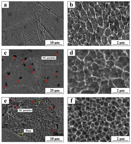
Figure 6.
SEM micrographs of the TiC/316Lss composites formed by SLM; (a,b) 0 wt% TiC, (c,d) 2 wt% TiC, (e,f) 4 wt% TiC.
During the SLM process of the TiC/316Lss composite, the wettability of the 316Lss powder can be increased by the TiC particles []. The wettability between TiC and 316Lss also affects the microstructures of the composites formed by SLM. The liquid phase contact angle θeq can be approximated by []:
where γsl, γsg, and γlg are the surface tensions at the solid–liquid, solid–gas, and liquid–gas interfaces, respectively, meaning that the interface bonding strength is high. TiC particles can affect cell growth orientation, promote the formation of small angle cell boundaries, and refine the structure. The increase of cell boundaries hinders dislocation movement, and at the same time, TiC cells can be bound to cell boundaries. However, excessive TiC particles will agglomerate in the local area. An EDS analysis of these particles and the diffusion area in the material after adding different content of TiC shows that they mainly contained Ti and Fe elements, as shown in Figure 7. When 2 wt% TiC was added, the content of Ti in Spot 1 reached 88.52%, while that in Spot 2 at the boundary was 62.4%, which was significantly higher than that in Spot 3 (1.33%) and Spot 4 (1.62%). The content of Ti in Spot 5 was 8.34%, which was between the two. Similarly, as shown in Figure 8, when 4 wt% TiC was added, the content of Ti in Spot 1 reached 70.86%, and in Spot 3 it reached 72.66%, while in Spot 2 the content of Ti was 47.22%, which is significantly higher than that in Spot 4 (1.62%). According to the content of the Ti element, the TiC particles, stainless steel matrix, and diffusion zone can be distinguished.
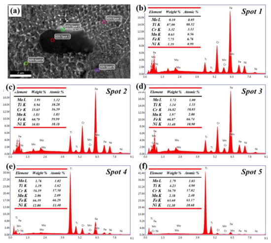
Figure 7.
High magnification SEM images of the side views of the 2 wt% TiC/316L composites formed by SLM (a); and energy-dispersive X-ray spectral (EDS) spot analysis of (b) Spot 1; (c) Spot 2; (d) Spot 3; (e) Spot 4; and (f) Spot 5.
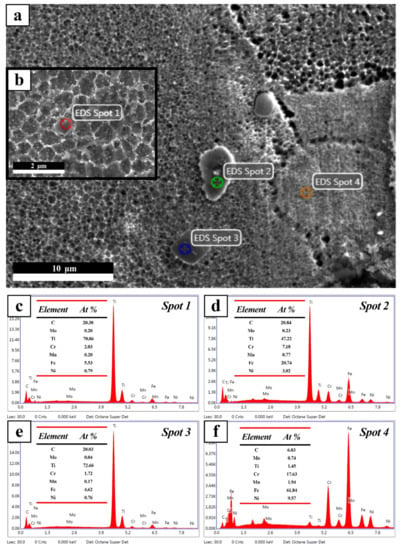
Figure 8.
High-magnification SEM images of the side views of the 4 wt% TiC/316L composites obtained by SLM (a,b); and EDS spots analysis of (c) Spot 1; (d) Spot 2; (e) Spot 3; and (f) Spot 4.
Figure 9 shows the TEM micrographs and EDS element mapping of 2 wt% TiC/316Lss formed by SLM, and the microstructure corresponding to different element types is further clarified. The results show that the main elements in the bulk materials were distributed evenly. Under the same magnification, the Fe, Ti, and C energy spectra clearly show the 316Lss phase and TiC phase. By combining the SEM microstructure and the EDS map, it was confirmed that TiC/316Lss composites were formed by SLM, and the elements were evenly distributed, which greatly enhanced the mechanical properties of the composites.
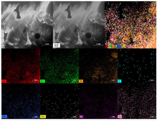
Figure 9.
TEM micrographs and EDS element mapping of 2 wt% TiC/316Lss formed by SLM.
Figure 10 shows the variation in the microhardness of the TiC/316Lss metal matrix composites with different TiC ratios. This hardness value was also observed during other investigations of the SLM of 316Lss [,]. The hardness of SLMed 316Lss is comparable to that of forging parts []. The results show that with the increase of the content of TiC, the microhardness of the metal matrix composites increased significantly. Compared with pure 316Lss HV0.2 (298.3), the average microhardness of the parts formed by adding 2 wt% TiC increased by 12.4%, to 335.2 HV0.2, and to 321.5 HV0.2 after adding 4 wt% TiC. Our relevant results are consistent with those of previous studies []. The average microhardness of the parts formed by adding 4 wt% TiC increased by 7.78%. The hardness of the composites with 2% and 4% TiC was higher than that without TiC. This is because the distribution of TiC in the composites is uniform after adding 2% TiC. The distribution of TiC particles is not uniform after adding 4% TiC, as shown in Figure 8, and as the density of the composites decreases, the relative density of the different TiC contents (2%, 4%) sample was 93.2% and 92.4% respectively. In addition, TiC particles can refine cells to form fine cell strengthening. At the same time, TiC particles are dispersed to strengthen metal matrix composites. The addition of TiC particles makes the cell size decrease obviously. The refinement of cell size results in the increase of cell boundaries, and more cell boundaries hinder the movement and propagation of dislocations, thus increasing the strength, and subsequently improving the hardness of the metal matrix composites. In addition, the addition of a TiC phase with a higher hardness value tends to increase the hardness of the composites similarly [,]. The strengthening mechanism of the metal matrix composites formed by SLM mainly included TiC particle strengthening and Ti element solution strengthening. Meanwhile, the mechanical properties of formed parts are also affected by density and structural defects. Since the heating and cooling speed of the SLM process is very fast, the microstructure of the reinforced structure is obviously refined, and the hardness value is maximized. There are two key factors for cell refinement by adding TiC particles. Firstly, the TiC in the molten pool plays the role of the nucleation centre in the solidifying process, promoting the formation of the equiaxed austenite cells through hindering []. Another point is that the TiC has a much higher thermal conductivity (70 W/MK) than the 316Lss matrix (15 W M‒1 K‒1), which promotes the thermal transmission during the fast melting–solidification process. This process significantly increases the cooling and solidification rates, and further decreases the thermal residual stress.
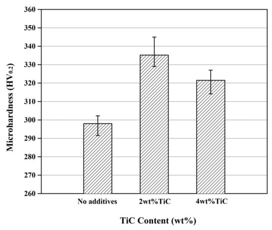
Figure 10.
Microhardness of the TiC/316L composites obtained by SLM.
Hanumanth et al. [] reported that adding the ceramic particle reinforced phase caused an increasing of the cooling rate and the solidification rate for the composites. TiC particles were sparsely distributed at the cell boundaries, which increased the hardness value. Similar results have been reported by Almangour et al. [] for improving the hardness of the SLM composites by cell refinement and cell boundary strengthening after adding the TiC. In addition, studies have shown that microhardness is closely related to wear resistance, and the wear resistance significantly increased along with the increase of microhardness. Several researches have studied the relationship of microhardness and wear resistance, and found that the microhardness is linearly correlated with wear resistance [,,,].
The surface morphology of the samples after friction and wear are shown in Figure 11; the microstructural characteristics of wear are highlighted. The load of 30N, sliding speed of 100 mm/min, and sliding friction for 30 minutes were used in the test, and the relationship between friction coefficient and time was obtained, as shown in Figure 12. Attar et al. obtained similar results [,,]. When adding 2 wt% TiC particles (Figure 11c), the metal matrix composites manufactured by the SLM had the smallest friction coefficient of 0.123. The wear surface of the SLM part forms parallel grooves that exhibit abrasive wear. When adding 4 wt% TiC particles (Figure 11e), the friction coefficient of metal matrix composites manufactured by SLM increased to 0.401. From the outline of the wear surface, it can be seen that the grooves produced by wear were obvious, and accompanied by the phenomenon of debris accumulation. Compared with those without TiC particles (Figure 11a), the friction and wear properties were improved, but the change was stable, which indicated that the friction and wear properties were stable. When 2 wt% TiC particles were added (Figure 11d), the inner furrow was clear, straight, and parallel to the direction of friction pair movement; the wear mechanism was abrasive wear. When 4 wt% TiC particles were added (Figure 11e), the debris adhered to the edge of the wear marks, and the furrows became deeper in the wear marks of the metal matrix composites. The larger wear debris further exerted a force on the composite material, and the greater the shear strain, the more serious the delamination of the mechanical mixing layer (MML) or the subsurface layer. This is because the porosity of the forming materials increased and the density decreased with the increasing of the addition amount.
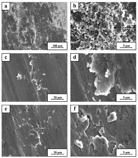
Figure 11.
SEM images showing the typical worn morphologies of TiC/316Lcomposites with different volume contents; (a,b) 0 wt% TiC, (c,d) 2 wt% TiC, and (e,f) 4 wt% TiC.
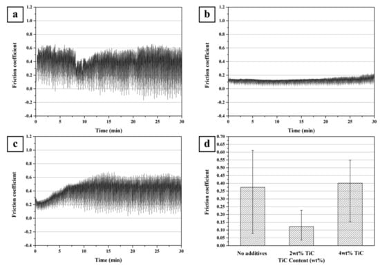
Figure 12.
Coefficients of friction of the samples formed by SLM: (a) Pure 316L sample and the samples of the TiC/316Lss composites with different TiC contents: (b) 2 wt% TiC, (c) 4 wt% TiC, and (d) average friction coefficient.
Figure 13 displays the potentiodynamic polarisation curves of the SLM-produced 316Lss alloy and the TiC/316Lss composites with different TiC reinforcement volume contents in 3.5% NaCl solution. It is evident that the polarisation curves of the three types of samples had very good reproducibility. It can also be seen that with the increasing of the content of TiC, the corrosion rate of TiC/316Lss alloy formed by SLM first decreased, and then increased. By analysing the Tafel polarisation curve, it can be found that the passivation current and dimension passivation current of the sample with 2 wt% TiC addition were smaller than those without TiC addition, and the addition of 4 wt% TiC was larger than that with 2 wt% TiC addition. According to the dynamic potential curve, it is concluded that the addition of 4 wt% TiC/316Lss alloy samples produced by SLM shows that the corrosion resistance of the alloy in a wide range of potential was worse than that of adding 2 wt% TiC/316Lss alloy, which is better than that of the sample that was not added. The more passivation current, the easier the passivation of the alloy; that is to say, the more easily the passivation film is formed, the more resistant the alloy is to corrosion (corrosion potential is a thermodynamic factor); the smaller the passivation current, the better the protectiveness of passivation film, indicating that the alloy is more resistant to corrosion []. Figure 12 shows the corrosion rate of SLM-formed TiC/316Lss alloy after adding different TiC contents. The corrosion rate of the alloy was very low as a whole, and after adding 4 wt% TiC, it was slightly higher than that which had 2 wt% TiC added. The main reason for the above phenomenon is that after adding TiC, a passive oxide layer is formed, and the TiC is uniformly distributed. In the SLM process, the denser structure and less segregation make the distribution of Cr and Ni more uniform. Among these elements, Ni helps improve the thermodynamic stability of the alloy, and greatly improves the corrosion resistance of the reducing medium in the forming material. As an element with high passivation ability, Cr can improve the passivation ability of SLM moulding products, so as to improve the corrosion resistance. The increased corrosion resistance of the material is due to the formation of a passive oxide layer due to the presence of Cr in the material. With the increasing of the content of TiC, the distribution of TiC was not uniform, and with the spheroidisation effect, the density and corrosion resistance of the samples formed by the SLM decreased. According to the dynamic potential curve, it is concluded that the addition of 4 wt% TiC/316LSS alloy samples produced by the SLM shows that the corrosion resistance of the alloy in a wide range of potentials was worse than that of adding 2 wt% TiC/316LSS alloy, which was better than that of the sample that did not have any added TiC.
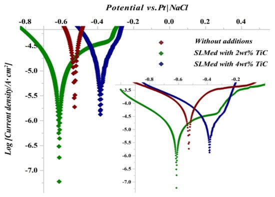
Figure 13.
Potentiodynamic curves for the TiC/316L composites formed by SLM with different TiC contents of in 3.5% NaCl solution.
4. Conclusions
This study has investigated the influence of the TiC mass fraction on the microstructure evolution, microhardness, friction properties, wear properties and corrosion resistance of the TiC/316Lss composites. The main research results can be summarised as follows:
- (1)
- With the increasing of the content of TiC, the microhardness of the metal matrix composites increased significantly, and the friction and wear properties first increased, and then decreased. Among them, adding 2 wt% TiC had the best moulding performance, which was formed under the optimised process parameters. Compared with the pure 316Lss (298.3HV0.2), the average microhardness of the parts formed by adding 2 wt% TiC increased by 12.4%, to 335.2HV0.2, and the average friction coefficient of the parts formed by adding 2 wt% TiC was 0.123.
- (2)
- With the increasing of the content of TiC, the corrosion rate of TiC/316L alloy formed by SLM first decreased, and then increased. The passivation current and dimension passivation current of the samples with 2 wt% TiC addition were smaller than those without TiC addition, and that with 4 wt% TiC added was larger than that with the addition of 2 wt% TiC. The higher the passivation current, the easier the passivation of the alloy, that is to say, the more easily the passivation film is formed; thus, the alloy is more corrosion-resistant. Moreover, the smaller the passivation current, the better the protectivity of the passivation film, indicating that the alloy is more corrosion-resistant.
Author Contributions
Conceptualization, Z.Y. and P.B.; investigation, Z.Y., J.L., H.Q., M.J., H.H., P.C. and L.Y.; Methodology, M.J., H.H., H.L. and J.X.; data curation, Z.Y., J.L., L.Y. and H.Q.; writing—original draft preparation, Z.Y. and P.B.; writing—review and editing, H.L. and J.X.
Funding
This research was funded by the National Natural Science Foundation of China (Grant No. 51775521 and 51604246), the Natural Science Foundation of Shanxi Province: 201801D221154, the International Science and Technology Cooperation Program of Shanxi Province through project NO:201603D421024, and Research Project Supported by Shanxi Scholarship Council of China through project NO:2017-095, the supports of the North University of China for Young Academic Leaders.
Conflicts of Interest
The authors declare no conflict of interest.
References
- Zhao, Z.; Bai, P.; Guan, R.; Murugadoss, V.; Liu, H.; Wang, X.; Guo, Z. Microstructural evolution and mechanical strengthening mechanism of Mg-3Sn-1Mn-1La alloy after heat treatments. Mater. Sci. Eng. A 2018, 734, 200–209. [Google Scholar] [CrossRef]
- Liu, H.; Sun, F.; Sun, H. Analysis of microstructure and mechanical properties of ultrafine grained low carbon steel. J. Wuhan Univ. Technol. Mater. Sci. Ed. 2016, 31, 1099–1104. [Google Scholar] [CrossRef]
- Liu, B.; Bai, P. Selective Laser Melting Process of Fe-Ni Metal Powder. Rare Met. Mater. Eng. 2011, 40, 241–244. [Google Scholar]
- Hou, H.; Li, Y.; Xu, X. Non-equilibrium effects on solid transition of solidification microstructure of deeply undercooled alloys. Mater. Sci. Technol. 2017, 34, 1–6. [Google Scholar] [CrossRef]
- Xu, H.; Deng, X.; Zhang, X.; Zhang, K.; Liu, Y.; Li, S. Relationship between heat treatment and corrosion behavior of Mg-15Y alloy. J. Wuhan Univ. Technol. Mater. Sci. Ed. 2015, 30, 796–803. [Google Scholar] [CrossRef]
- Zhao, Z.; Li, L.; Bai, P.; Jin, Y.; Wu, L.; Li, J.; Guan, R. The heat treatment influence on the microstructure and hardness of TC4 titanium alloy manufactured by SLM technology. Materials 2018, 11, 13181–131812. [Google Scholar]
- Lin, S.; Xiong, W.; Wang, S. Effect of reinforcing particles content on properties of TiC/316L composites. Mater. Sci. Eng. A 2013, 18, 373–378. [Google Scholar]
- Almangour, B.; Grzesiak, D.; Yang, J. Nanocrystalline TiC-reinforced H13 steel matrix nanocomposites fabricated by selective laser melting. Mater. Des. 2016, 96, 150–161. [Google Scholar] [CrossRef]
- Almangour, B.; Grzesiak, D.; Yang, J.M. Rapid fabrication of bulk-form TiB2 /316L stainless steel nanocomposites with novel reinforcement architecture and improved performance by selective laser melting. J. Alloy Compd. 2016, 680, 480–493. [Google Scholar] [CrossRef]
- Jin, C.; lucknett, K.P. Microstructure instability in TiC-316L stainless steel cermets. Int. J. Refract. Met. H 2016, 58, 74–83. [Google Scholar] [CrossRef]
- Attar, H.; Ehtemam-Haghighi, S.; Kent, D.; Dargusch, M. Recent developments and opportunities in additive manufacturing of titanium-based matrix composites: A review. Int. J. Mach. Tools Manuf. 2018, 133, 85–102. [Google Scholar] [CrossRef]
- Zhao, Z.; Guan, R.; Zhang, J.; Zhao, Z.; Bai, P. Effects of process parameters of semisolid stirring on microstructure of Mg-3Sn-1Mn-3SiC (wt%) strip processed by rheo-rolling. Acta Metall. Sin. (Engl. Lett.) 2017, 30, 66–72. [Google Scholar] [CrossRef]
- Li, Z.; Xu, R.; Zhang, Z.; Kucukkoc, I. The influence of scan length on fabricating thin-walled components in selective laser melting. Int. J. Mach. Tool Manuf. 2018, 126, 1–12. [Google Scholar] [CrossRef]
- Zhao, Z.; Bai, P.; Li, L.; Li, J.; Wu, L.; Huo, P.; Tan, L. The Reaction Thermodynamics during Plating Al on Graphene Process. Materials 2019, 12, 330. [Google Scholar] [CrossRef] [PubMed]
- Zhao, Z.; Misra, R.; Bai, P.; Gao, J.; Li, Y.; Guan, R.; Guo, Z. Novel process of coating Al on graphene involving organic aluminum accompanying microstructure evolution. Mater. Lett. 2018, 23, 202–205. [Google Scholar] [CrossRef]
- Li, W.; Li, S.; Liu, J.; Zhang, A.; Zhou, Y.; Wei, Q.; Yan, C.; Shi, Y. Effect of heat treatment on AlSi10Mg alloy fabricated by selective laser melting: Microstructure evolution, mechanical properties and fracture mechanism. Mater. Sci. Eng. A 2016, 663, 116–125. [Google Scholar] [CrossRef]
- Kong, D.; Ni, X.; Dong, C. Heat treatment effect on the microstructure and corrosion behavior of 316L stainless steel fabricated by selective laser melting for proton exchange membrane fuel cells. Electrochim. Acta 2018, 276, 293–303. [Google Scholar] [CrossRef]
- Suryawanshi, J.; Prashanth, K.; Ramamurty, U. Mechanical behavior of selective laser melted 316L stainless steel. Mater. Sci. Eng. A 2017, 696, 113–121. [Google Scholar] [CrossRef]
- Lou, X.; Song, M.; Emigh, P. On the stress corrosion crack growth behaviour in high temperature water of 316L stainless steel made by laser powder bed fusion additive manufacturing. Corros. Sci. 2017, 128, 140–153. [Google Scholar] [CrossRef]
- Tucho, W.; Lysne, V.; Austb, H. Investigation of effects of process parameters on microstructure and hardness of SLM manufactured SS316L. J. Alloy Compd. 2018, 740, 910–925. [Google Scholar] [CrossRef]
- Stašić, J.; Božić, D. The effect of NiB additive on surface morphology and microstructure of 316L stainless steel single tracks and layers obtained by SLM. Surf. Coat. Technol. 2016, 307, 407–417. [Google Scholar] [CrossRef]
- Yadollahi, A.; Shamsaei, N.; Thompson, S.; Seely, D. Effects of process time interval and heat treatment on the mechanical and microstructural properties of direct laser deposited 316L stainless steel. Mater. Sci. Eng. A 2015, 644, 171–183. [Google Scholar] [CrossRef]
- Almangour, B.; Grzesiak, D.; Yang, J.-M. Selective laser melting of TiC reinforced 316L stainless steel matrix nanocomposites: Influence of starting TiC particle size and volume content. Mater. Des. 2016, 104, 141–151. [Google Scholar] [CrossRef]
- Song, B.; Dong, S.; Coddet, C. Rapid in situ fabrication of Fe/SiC bulk nanocomposites by selective laser melting directly from a mixed powder of microsized Fe and SiC. Scr. Mater. 2014, 75, 90–93. [Google Scholar] [CrossRef]
- Chang, F.; Gu, D.; Dai, D. Selective laser melting of in-situ Al4SiC4 + SiC hybrid reinforced Al matrix composites: Influence of starting SiC particle size. Surf. Coat. Technol. 2015, 272, 15–24. [Google Scholar] [CrossRef]
- Agarwala, M.; Bourell, D.; Beaman, J. Direct selective laser sintering of metals. Rapid Prototyp. 1995, 1, 26–36. [Google Scholar] [CrossRef]
- Yuan, P.; Gu, D.; Dai, D. Particulate migration behavior and its mechanism during selective laser melting of TiC reinforced al matrix nanocomposites. Mater. Des. 2015, 82, 46–55. [Google Scholar] [CrossRef]
- Wilson, J.; Shin, Y. Microstructure and wear properties of laser-deposited functionally graded Inconel 690 reinforced with TiC. Surf. Coat. Technol. 2012, 207, 517–522. [Google Scholar] [CrossRef]
- Hanumanth, G.; Irons, G. Solidification of particle-reinforced metal-matrix composites. Metall. Mater. Trans. B 1996, 27, 663–671. [Google Scholar] [CrossRef]
- Song, B.; Dong, S.; Liao, H. Characterizations of tic particle reinforced FeAl composite part fabricated by selective laser melting. Mater. Res. Innov. 2014, 18, 50–56. [Google Scholar] [CrossRef]
- Li, J.; Zhao, Z.; Bai, P. Microstructural evolution and mechanical properties of IN718 alloy fabricated by selective laser melting following different heat treatments. J. Alloy Compd. 2018, 772, 861–870. [Google Scholar] [CrossRef]
- Ehtemam-Haghighi, S.; Prashanth, K.; Attar, H.; Chaubey, A.; Cao, G.; Zhang, L. Evaluation of mechanical and wear properties of TixNb7Fe alloys designed for biomedical applications. Mater. Des. 2016, 111, 592–599. [Google Scholar] [CrossRef]
- Attar, H.; Ehtemam-Haghighi, S.; Kent, D.; Okulov, I.; Wendrock, H.; Bӧnisch, M.; Volegov, A.; Calin, M.; Eckert, J.; Dargusch, M. Nanoindentation and wear properties of Ti and Ti-TiB composite materials produced by selective laser melting. Meter. Sci. Eng. A 2017, 688, 20–26. [Google Scholar] [CrossRef]
© 2019 by the authors. Licensee MDPI, Basel, Switzerland. This article is an open access article distributed under the terms and conditions of the Creative Commons Attribution (CC BY) license (http://creativecommons.org/licenses/by/4.0/).