Abstract
The internal recycling of iron-rich fine residues is a crucial process for reducing the raw material loss and the carbon footprint in sustainable ironmaking and steelmaking. Traditionally, cement has been used as a binder to ensure the structural integrity of agglomerates during transport and charging. While cementitious binder can achieve the necessary structural support, it contributes significantly to the carbon footprint. This study investigated the effects of alternative biogenic binders and varying compaction pressures on the physical and mechanical properties of agglomerates produced from three different types of fine residues from steel (SR) and cast-iron (FR) production. In addition, the self-reducing capability and degree of metallization of these agglomerates were evaluated through pyrometallurgical experiments in a Tammann furnace. The resulting agglomerates exhibited sufficient mechanical strength and high iron recovery rates. These findings confirm that biogenic binders can effectively replace cementitious binders without compromising the self-reduction performance of the agglomerates.
1. Introduction
In several production steps of iron- and steelmaking, large volumes of dusts are generated and require additional cleaning systems from the furnace or converter off-gas streams to protect the environment. During the year 2020, a cumulative mass of 1.66 × 10⁶ t of dusts and sludges were reported by [1] from the steelmaking industry in the German-speaking regions of Europe, indicating that 1.45 × 10⁶ t (app. 87%) were produced in integrated steel plants. In general, the utilization rate of dusts and sludges from off-gas filter systems accounts for 1.46 × 10⁶ t in the year of 2020 (88%), corresponding with the utilization rates of the recent decade [2,3]. However, according to [1,4] it was observed that over 200,000 t of filter dusts and sludges were landfilled in that year and a previous study [5] reported Fe-oxide abundances in blast furnace (BF) filter sludges, for instance, up to 50 wt.%.
Owing to this substantial Fe content of filter dust and sludge, these materials are subjected to internal recycling via different facilities such as the sinter plant in integrated steelmaking or directly in the electric arc furnace (EAF) in electric steel mills [4].
Some quantities of dusts and sludges, mostly originating from the converter process, are transported to external recycling facilities depending on the Zn concentration [6]. The external recycling route is most common for dusts and sludges from the EAF steelmaking process because they often contain Zn levels up to 30 wt.% [7,8]. Regarding the recovery of iron from such high-Zn-containing residues, [7] suggested using agglomerates within the OxyCup process as a cost-effective and environmentally friendly way, alongside well-established processes such as the Waelz Process, recently explained by [8]. In addition to the presence of Zn and other contaminants (e.g., Cu and Cd), additional physical parameters, such as the high moisture content in sludges and the very fine particle size distribution, impede the direct use of the materials in the recycling stream. As a result, a considerable amount of Fe gets lost to landfill rather than being recycled [4,5].
Another issue arising from internal recycling of dusts and sludges within integrated steelmaking results from the massive transformation toward more environmentally friendly production methods in the steel industry. As part of this movement, alternative and sustainable processes have been developed, such as using DRI or hydrogen (H2) reduction in EAFs or submerged arc furnaces (SAFs) instead of conventional fossil-fuel-based blast furnaces to reduce CO2 emissions. Consequently, blast furnaces as well as sinter plants will no longer be available for internal recycling. For cupola and other shaft furnace types, several authors have demonstrated the feasibility of agglomerates and briquettes produced by various techniques [9,10,11,12,13]. A brief comparison of different agglomeration methods for the production of self-reducing agglomerates is given by [14]. For the use in shaft furnaces, ref. [4] suggested that the minimum cold compressive strength (CCS) of the agglomerates should be at least 12 MPa to guarantee the column stability in the shaft when agglomerates are charged. In addition to the cold compressive strength, porosity is also a key parameter for such an application, and it should exceed the theoretical value of 21.5% for sinter to allow the adequate passage of reduction gases through individual agglomerate [5]. As demonstrated by [15], the porosity of the agglomerate does not significantly contribute to the self-reduction of the Fe-oxides when compared to the effect of composition and applied temperature at the laboratory scale. In shaft furnace systems, however, reduction gases such as carbon monoxide (CO), methane (CH4), and hydrogen (H2) must traverse the entire column to guarantee the complete reduction of the Fe-oxide feed. The column permeability can be modified by adjusting the feed composition, which may include sinter, lump ore, pellets and scrap metal (in the cupola shaft).
Other benefits of agglomerated materials, especially for fine-grained residues, are the simplified material transport and facilitated storage due to compact compression of said materials [9]. Distinct methods of agglomeration include sintering, pelletizing, and briquetting, also called press agglomeration [9]. In contrast to pelletizing, less binder is required in briquetting. Up to 15% of binders are added to the production of pellets, while consumption in press agglomeration is mostly below 6% [14], which comes along with an increase in the agglomerate’s payload.
For a production volume below 20,000 t/a, press agglomeration using smaller stamping presses can be a cost-effective method, owing to their smaller Capital Expenditure (CAPEX) and Operational Expenditure (OPEX) [10,15]. This is particularly important for small and medium-sized enterprises with a low volume of residual materials. In addition, different briquette shapes and sizes can be produced due to the different pressing machines and die attachments. Due to the freely adjustable pressing force of the machines, lower porosity, higher densities, and thus also higher strengths can be achieved. Also, due to the high pressure, brittle particles can break. This results in smaller particles that fill in the remaining gaps. This lowers the particle spacing, which therefore increases the strength of the agglomerates. Another advantage of press agglomeration is that it is largely independent of the size of the particle to be compressed down to the finest particle sizes.
Press agglomeration is carried out with or without the addition of binder. If no binder is used, the increase in strength is largely due to the form-fitting bonding by the interlocking of particles. This effect is particularly effective with deformable particles and fibrous material and thus is widely used to recycle metal chips from the post-capable of creating liquid bridge processing in foundries. When binders are added, the formation of solid-state bridges through crystallization contributes significantly to the increase in strength [4,14]. Usually, up to 6 wt.% of binders are used [16]. In addition to the adhesive strength of the binders, bound water from the binder mixture or the used raw material is capable of creating liquid bridges which can add some total strength [16].
However, for most of the used agglomerate bricks, nowadays, Portland cement is utilized as a binder, introducing a high carbon footprint [17,18]. In the context of the advancing climate crisis, the CO2 footprint of about 875–910 kg CO2 per ton of cement (Scope 1 and 2 emissions) is a considerable environmental impact [3]. Regarding the metallurgical recycling of the materials, the use of cement as a binder results in further disadvantages [12]. Due to the use of cement, the amount of water required for the cement reaction and workability, and the subsequent hardening or carbonation of the agglomerate bricks, the material content is diluted. Water and CO2 must be expelled in the metallurgical process, requiring additional energy. In any case, the cement content must also be melted in the metallurgical process, requiring additional energy input. Depending on the raw material mix in the metallurgical process, the cement mineralogy must also be considered when adjusting the required slag composition and thus be compensated for by the additional input of slag-forming raw materials such as dolomite, limestone, burnt limestone or a SiO2 source.
In contrast, organic binders such as starch or molasses can be produced nearly CO2-neutrally and have no effect on the melt and slag chemistry of the metallurgical process while also being comparable to state-of-the-art binder in cost-efficiency [4,19]. One further advantage is the hygroscopicity of starches, which tend not to absorb any moisture and prohibit potential swelling [18].
Economic efficiency can be shown by comparing the typical composition of cementitious agglomerates with agglomerates produced with an organic binder produced via a stamp press, as shown in Figure 1.

Figure 1.
Comparison of typical compositions of cement- and organic-bonded agglomerates (mod. after [20,21,22]). Adapted with permission from ref. [22]. 2019, Associazione Italiana di Metallurgia.
It can be shown that cement-bound agglomerates are only used to 74% of their total weight, as the water evaporates and the cement remains in the slag. Both water and cement require additional energy to melt and evaporate. In particular, the highly endothermic carbonate trap of cement increases the energy requirement. The higher water content of the cementitious agglomerates is due to the crystalline bound water in the cement. Organically bound agglomerates have a payload of about 97%, as only the water is not used for the solidification and hardening processes [13]. Due to the carbon content in organic binders, their use also serves as an energy and/or reducing agent input into the process.
The aim of self-reducing agglomerates is the reduction of the oxidic metal compounds they contain. This concerns the reduction of iron oxides to metallic iron. The determination of the carbon requirement is based on the reaction equations and the individual stoichiometric factor of the reduction of the oxides contained in each of the raw materials. To ensure a complete reduction of the oxides, up to double the stoichiometric amount in the form of coke was used. For the used coke, a carbon content of up to 100 wt.% is assumed, taking into account the proven higher quality standard of the used coke. In addition, the organic binders also contribute as carbon carriers for the self-reduction. Beyond this, no other reducing agents are added to the process.
Thus, press agglomeration tends to be a universal technique capable of handling different types of residues if operated with batches of similar material flows such as chips and other fine-grained residues. For the target-oriented agglomeration of different residues, however, detailed knowledge of the input materials is important both for meeting the requirements and for selecting the appropriate processing method. This includes, in particular, the particle size and particle adhesion brought by the binder. Characteristics should be considered, for example regarding the moisture, shape, size or homogeneity of the input material. A certain minimum strength is almost always required.
In this study, cement-free stamp press agglomeration was surveyed with exemplary Fe-containing dust and sludge residues for the development of sustainable Fe-recycling in the iron and steel making industry. Therefore, sample materials were characterized by chemical and mineralogical methods as well as physical properties in terms of particle size distribution (PSD) to develop binder–water-reduction agent recipes from which agglomerate bricks were produced with a stamp press. The produced agglomerates were subjected to tests for cold compressive strength as well as self-reducing properties in lab-scale furnace experiments to evaluate the suitability of the created recipes for their mechanical and self-reducing properties. The produced metal and oxidic fractions were investigated for their metal content to evaluate the self-reduction. Furthermore, the environmental impact of using organic binders instead of cement was assessed by a simple LCA (life cycle assessment).
2. Materials and Methods
2.1. Raw Materials
For the investigations 3 different dust and sludge samples from different iron and steelmaking processes as well as from metal casting were selected for further analysis. The main emphasis of the presented selection lies on the fine particle size with ongoing high amounts of total Fe. As shown in Table 1, samples FR-1 and FR-2 originate from the different filter assembly lines of one foundry located in Germany producing all kinds of standardized cast iron products. Sample SR-1 was taken from a dedusting assembly of a German steel plant operating two BOFs (basic oxygen furnaces) to produce steel from pig iron. The filter is only applied for cleaning the dust and sludge from the off-gas of the BOF facility. The reddish material exhibits a high initial moisture of 20.4 wt.% and shows a certain tendency of clogging.

Table 1.
Sample list with different types and origins of sample material.
2.2. Analytical and Experimental Procedures
The particle size distribution (PSD) of each sample material was determined by laser diffraction analysis (LA-300, Horiba, Kyoto, Japan) in ethanol suspension. The disintegration of agglomerates was conducted with ultrasonic treatment at 15 W and 28 kHz for 1 min prior to analysis. By repetitive analysis of the same sample portion, stable sample dispersion was guaranteed. The chemical compositions of the materials were investigated by X-ray fluorescence (XRF) conducted on Li-borate fusion discs with a Zetium instrument (Malvern Panalytical, Malvern, UK). The mineralogical composition was identified by X-ray diffraction (XRD) using an X’Pert Pro MPD instrument (Malvern Panalytical, Malvern, UK). The sample powders were measured semi-quantitatively between 2-theta angles of 5–75 ° using CuKα1 radiation (45 kV, 40 mA).
Sets of 3 agglomerates were tested each for cold compressive strength using a testing press (Universaldruckprüfmaschine 3.362, Fröwag, Obersulm, Germany). Based on brick dimensions and weight, the skeleton density of each agglomerate was determined to calculate the compressive strength of the recorded pressure. Small quantities of agglomerate bricks were surveyed for the pore size distribution using a Hg-injection porosimeter (Pascal 140/440 series, Microtrac, Haan, Germany) at a maximum pressure of 400 MPa. On powdered agglomerate samples (<63 µm) heating microscopy experiments were conducted under N2 atmosphere to investigate the behaviour across a temperature window up to 1605 °C. For the experiments a Leitz heating microscope using the EMI 2 software suite (Hesse Instruments, Osterode am Harz, Germany) was used for furnace control and image acquisition. The heating rate was set to 10 °C/min in the temperature range <1000 °C. For the temperature range between 1000 °C and 1605 °C the heating rate was decreased to 5 °C/min for an enhanced temperature resolution. From 1000 °C on upwards, images of the observed silhouette of the specimen were recorded at 10 °C intervals.
For the lab-scale furnace experiments, a quarter-scale sample of the specific agglomerate brick was heated in a MgO crucible to a final temperature of 1600 °C in a N2 purged Tamman furnace. This temperature was held for at least 45 min. After the holding period the material was cooled overnight in the furnace still under inert conditions. Then, the solidified materials were carefully removed from the crucible and weighed for mass balance. After a gentle crushing of the materials, ductile and magnetic fraction were extracted by sieving and manual magnetic separation and assigned as “metal fraction”. A wet chemical extraction of Fe-species using Br–methanol solution was performed to determine the distribution of the metallic and divalent Fe in the metal fraction. For the calculation of the individual Fe-species distribution, the concentration of total Fe, excluding other trace elements, was determined with an iCap-R ICP-MS (Inductively coupled plasma-mass spectrometer) (Thermo Scientific, Waltham, MA, USA) after dissolution in concentrated HCl. The quantity of the trivalent Fe was computed from the obtained data. The non-magnetic brittle fraction retained from the crucible was designated as “oxidic” and was investigated by XRF and XRD for its individual chemical and mineralogical composition.
2.3. Agglomeration Methods
The mixing apparatus used was a Type LM-3e 10 L counterflow intensive mixer (Multiserw, Marcyporęba, Poland). The agglomerates were produced using a GT2244 hydraulic stamp press (Gabbrielli, Calenzano, Italy) capable of applying a maximum force of 80 tons. The equipment used is shown in Figure 2A and Figure 2B respectively. In the mixing process, once the mixing drum was closed, the agitator switched to the maximum agitator speed of 2820 revolutions per minute (rpm), and the mixing drum also started rotating at its maximum rotational speed of 60 rpm in the opposite direction of the agitator for 4 min. The initial mixing period and high-speed rotation were important not only to ensure the complete homogenization of the input material but also to promote the comminution of any clumped particles. Meanwhile, material adhering to the mixing drum was removed manually using a spatula to guarantee that all particles experienced the same binding force and therefore avoid potential weak spot formation. Likewise, if an additive is used, the added cellulose fibres are torn apart so that no “nests” form in the agglomerates. Subsequently, the mixing drum and agitator were changed to their minimum rotational speed of 4 and 200 rpm, respectively. After about 15 s at the lowest speed, the charging flap was opened, and the liquid input materials such as water or liquid binder were added. The short waiting time at low speed allowed fine particles and dust to settle, preventing them from escaping through the charging flap. The charging flap was then closed, and the materials were mixed at maximum rotational speed for 5 min. Afterwards, the agitator moved upwards, the mixing drum was removed and materials adhering to the drum wall were collected using a spatula.
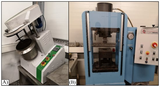
Figure 2.
(A) Mixer used to mix the raw materials and (B) agglomeration stamp press used.
To carry out the pressing process, the required pressing pressure was first set using the adjusting screw. For each recipe investigated, stamping pressures of 10 N/mm2, 20 N/mm2 and 40 N/mm2 were examined for each of the three agglomerates. The lower and upper punches were moved to the lowest and the highest positions, respectively. Then, the die was slowly filled up with the material to the top edge to enable the die cavity to have better filling, reducing lumps inside. Subsequently, the upper punch moved downwards until the set pressing pressure was reached, followed by a holding time of a few seconds. After the holding period, the upper punch was raised first and then the lower punch moved upwards, pushing out the produced agglomerate. Finally, the agglomerate was removed from the stamp press and the lower punch returned to its lowest position for the next agglomeration step.
2.4. Used Binders and Additives
The different organic binders used for the agglomeration of the investigated raw materials were potato starch (Avedex Dextrin, Avebe, Karstädt, Germay) and wheat starch (Crespotec, Crespel and Deiters, Ibbenbüren, Germany), both of industrial quality. Foundry coke and cellulose fibres were used as additives. The organic fibres, which consist of glucose (C12H20O10), were used to increase the green compressive strength of the agglomerates. Here, the form-fitting binding, i.e., the interlocking of particles, comes into play [21]. Particularly in the case of materials that are difficult to agglomerate, the time between agglomeration and heat treatment is bridged to increase the strength without the agglomerates disintegrating [21].
Another beneficial mechanism in the use of cellulose fibres as additives is the pore-forming potential in agglomerates. The decomposition temperatures of the fibres are usually reached earlier than the melting temperature of the raw material. As a result, the fibrous materials can be burnt off at elevating temperatures, leaving pores formed in the agglomerates [22]. In addition, cellulose fibres can be combusted without residues during melting processes, with no negative effects on melt or slag chemistry.
3. Results
3.1. Chemical and Mineralogical Properties of the Used Raw Materials
The filter dust samples (FR-1, FR-2) from the converter steel plant were classified as dry; thus, no caking was observed prior to the sample treatment. For sample SR-1, however, a moisture of 20.4 wt.% was determined. In Table 2, the chemical compositions of the samples from a dry basis investigation are given. Especially for the samples FR-1 and SR-1, total Fe2O3 contents >80 wt.% were determined. A significantly lower total Fe2O3 concentration of app. 60 wt.% was detected for the residual sample FR-2. The distribution of Zn in sample FR-1 was measured as a value lower than the detection limit (0.02 wt.%), whereas, for the samples FR-2 and SR-1, Zn concentrations of 2.4 wt.% and 4.9 wt.% were observed, respectively. The result for SR-1 indicates that this sample was taken from a converter steel plant using Zn-containing cooling scrap for the process. Other unwanted elements, with respect to iron and steelmaking, such as Pb, Cu, P, and Ni could be quantified at low and unproblematic concentrations levels. It is also notable that the table contains the concentration of other components such as MgO, SO3, Cr2O3 and so forth. Among them, lime, dolomitic lime and silicate are of interest as these are additives used for slag formation in the metallurgical processes.
Table 2.
Elemental composition (XRF, dry basis) of raw materials as received.
In Figure 3, the particle size distributions in the “as-received” state of the investigated sample materials are displayed. For the residue samples, the PSD range was significantly below 100 µm. For sample SR-1, it was characterized as the finest PSD with a D50 value of 3.5 µm among the residues. For the other samples, D50 values of 68.7 µm (FR-1) and 12.0 µm (FR-2) were observed, respectively. For the raw coke used, a D50 value of 85.9 µm was determined for the fraction <500 µm (38.4 wt.%).
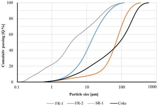
Figure 3.
Particle size distribution of the samples FR-1, -3, -4 and of the used coke determined by laser diffraction.
The mineralogical composition of the samples is given in Table 3. The corresponding interpreted X-ray diffraction patterns for the samples are displayed in Figure 4. As the patterns indicate, Femet is the dominant phase in FR-1; in samples SR-1 and FR-2, however, magnetite and hematite were the most abundant Fe-bearing minerals. Both samples show further limited amounts of wuestite. As a minor Fe-bearing carbonate phase, siderite was observed in sample FR-2. Calcite and moissanite (SiC) were detected only in sample FR-1. The latter carbide phase could be attributed to the final processing steps (polishing, blowing) of cast iron production and thereby can generally be expected in de-dusting materials from foundries. Despite containing no free Zn-phase, the notable Zn content of SR-1 (4.9 wt.%) will be incorporated in the spinel solid-solution series as the franklinite component in magnetite.
Table 3.
Mineralogical compositions of the used raw materials determined semi-quantitatively by XRD.
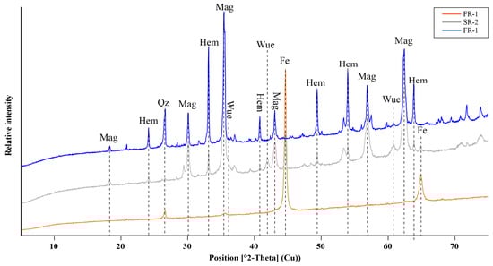
Figure 4.
XRD patterns of the investigated samples FR-1–FR-2, showing hematite (hem), magnetite (mag), wuestite (wue), quartz (Qz) and metallic Fe (Femet) as the most abundant Fe phases.
Based on the Fe mineral abundance and the amount of total Fe (as Fe2O3) in the respective samples, the distribution of Fe-species was calculated as seen in Table 4. Metallic Fe was the dominant Fe-phase in sample FR-1, while, as demonstrated in Table 4, di- and trivalent Fe were the dominating species in samples SR-1 and FR-2. In particular, ferric iron accounted for the largest proportion in sample FR-2, which can be attributed to the higher hematite content. The results of the chemical analysis for the coke used in the study are shown in Table 5. The coke contains more than 80 wt.% of carbon and features a sulfur content below 1 wt.% of sulfur. In total, volatile constituents were quantified to 45 wt.% and 88 wt.% by LOI determination at combustion temperatures of 550 °C and 950 °C, respectively. In addition, some trace elements were detected, indicating around 5000 ppm of Ca and 15,000 ppm of Al. The sources of these typical impurities are residual amounts of the fine-grained siliciclastic host rocks of the coals as slates as well as clay- and siltstones.
Table 4.
Distribution of Fe-species across the sample set, calculated by the nominal distribution of the Fe-bearing minerals normalized against the total Fe of each sample concentration.
Table 5.
Chemical composition of the used coke (dry basis).
3.2. Binder-Reduction Recipes
Based on the chemical compositions of the three raw materials, a set of recipes in combination with varying ratios of binders, cellulose fibres and coke was developed, as shown in Table 6. Specifically, to analyze the effects of the recipes and ratios on the mechanical properties and self-reducing ability of agglomerates, the different starch types and cellulose fibres in the form of different proportions were investigated. The coke content required for self-reduction was calculated according to the double-stoichiometric ratio in relation to the Fe-species found in the respective materials. Furthermore, coke was applied in excess of the stoichiometric requirement because overall carbon losses could not be neglected. In the furnace system used, the off-gas cannot be monitored with sufficient precision to evaluate carbon losses to gasification.
Table 6.
Composition of the mixture of materials for the preparation of agglomerates.
3.3. Compressive Strength Development
In Table 7, the mean cold compressive strength values of the agglomerates made of different recipes at stamping pressures of 10, 20, and 40 MPa are presented. The solid-coloured bars show recipes using potato starch as a binder, while the hatched bars represent those using wheat starch. When cellulose fibres are contained in the recipes, bars are characterized with a black border, with the border thickness indicating the fibre content.
Most agglomerates from the investigated recipes showed sufficiently high cold compressive strengths over 5 MPa. For further investigation, one recipe and stamping pressure combination of each raw material was chosen based on the highest cold compressive strength and processability. The selected combinations were FR-1-R3 at 40 MPa, FR-2-R2 at 10 MPa, and SR-1-R3 at 20 MPa. These recipes were subsequently examined by heating microscopy and furnace experiments.
Table 7.
Density of the agglomerates with various recipes, pressed at different compaction pressures, and their average cold compressive strength. Further used agglomerate recipes are marked in grey.
Table 7.
Density of the agglomerates with various recipes, pressed at different compaction pressures, and their average cold compressive strength. Further used agglomerate recipes are marked in grey.
| Recipe Nr. | Stamp Pressure [N/mm2] | Density [g/cm3] | Avg. Cold Compressive Strength [MPa] | Standard Deviation [MPa] |
|---|---|---|---|---|
| FR-1-R2 | 10 | 2.763 | 27.1 | 8.71 |
| 20 | 2.803 | 27.4 | 4.96 | |
| 40 | 2.854 | 27.9 | 5.74 | |
| FR-1-R3 | 10 | 2.746 | 30.3 | 3.54 |
| 20 | 2.586 | 26.5 | 1.85 | |
| 40 | 2.898 | 38.3 | 1.52 | |
| FR-1-R4 | 10 | 2.744 | 13.6 | 1.26 |
| 20 | 2.779 | 16.4 | 1.04 | |
| 40 | 2.872 | 21.3 | 2.47 | |
| FR-2-R1 | 10 | 2.156 | 8.8 | 1.82 |
| 20 | 2.209 | 12.3 | 1.28 | |
| 40 | 2.219 | 15.1 | 0.83 | |
| FR-2-R2 | 10 | 2.165 | 17.0 | 4.86 |
| 20 | 2.149 | 15.2 | 1.75 | |
| 40 | 2.109 | 15.4 | 0.52 | |
| FR-2-R7 | 10 | 1.928 | 2.6 | 0.61 |
| 20 | 2.005 | 2.9 | 0.32 | |
| 40 | 2.006 | 3.4 | 0.69 | |
| FR-2-R8 | 10 | 1.988 | 6.0 | 0.38 |
| 20 | 2.003 | 6.3 | 0.38 | |
| 40 | 2.008 | 5.3 | 1.08 | |
| SR-1-R1 | 10 | 2.097 | 14.1 | 1.95 |
| 20 | 2.101 | 18.5 | 1.09 | |
| 40 | 2.112 | 20.8 | 0.85 | |
| SR-1-R3 | 10 | 2.285 | 26.5 | 0.96 |
| 20 | 2.248 | 29.6 | 1.20 | |
| 40 | 2.265 | 28.6 | 0.52 |
3.4. Mercury Injection Porosimetry
Figure 5 displays the cumulative porosity and pore size distribution of the agglomerates for the recipes FR-1-R3, FR-2-R2 and SR-1-R3 at the three different compaction pressures of 10, 20 and 40 N/mm2.

Figure 5.
Cumulative porosity determined for the agglomerates of the samples FR-1 (orange), FR-2 (blue) and SR-1 (grey) for the 3 different compaction pressures of 10 (solid), 20 (points) and 40 (dashed) MPa. Measurement raw datasets are given in Appendix A.1, Appendix A.2 and Appendix A.3.
The highest porosity was observed with an abundance of 41.6% for sample SR-1-R3 compacted with a 20 N/mm2 stamp pressure. Similar values of 40.1% and 38.6% were observed for this sample. Conversely, the lowest porosities were measured with abundances between 21.7% and 24.3% for the agglomerates of sample FR-1-R3. The lowest value (21.7%) was achieved when the agglomerate was compacted at the stamping pressure of 40 N/mm2. For the samples of FR-2-R2, porosities observed ranged from 34.8% to 36.4% after Hg-injection experiments. Consequently, for all the agglomerates of the recipes FR-1, -2 and SR-1 produced, the porosities exhibit a 21.5% share introduced by [4], and, therefore, it can be assumed that the bricks produced are also suitable for use in shaft furnaces (cupola furnace, DRI furnace).
The pore size distribution for the material showed a steep slope at pore diameters greater than 16.25 µm, indicating a significantly higher proportion of large pores and a more discrete distribution across all the tested stamping pressures.
3.5. Heating Microscopy
In Figure 6 the recorded change in the observed area along the furnace programme are shown for the samples FR-1, -2 and SR-1. Corresponding images of the observed specimen silhouettes are given in Figure 7.

Figure 6.
Observed change in area under heating microscopy experiments for the samples FR-1 (orange), FR-2 (blue) and SR-1 (grey). The black curve shows the heating rates of 10 °C/min up to 1000 °C and 5 °C/min for the temperature range above 1000 °C.
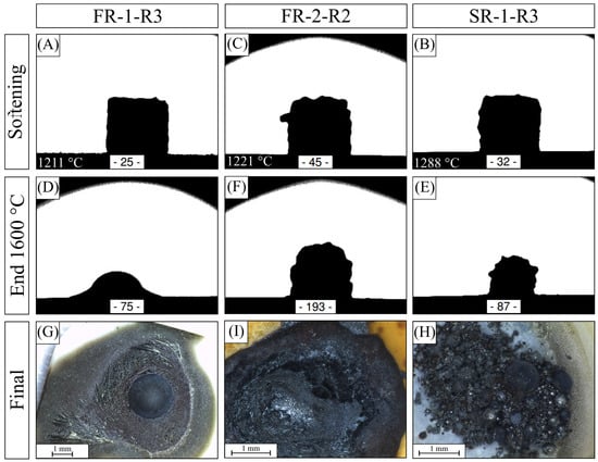
Figure 7.
Detected softening temperatures and corresponding specimen silhouettes (A–C). Images of the specimen silhouettes at the end of the experiments at 1600 °C (D–F). Images of the sample materials after the heating microscopy experiments (G–I). Bulb-shaped residues are produced by the experiments on samples FR-1-R3 (G) and FR-2-R2 (I). For sample SR-1-R3 (H) the disintegrated material reveals round particles of metallic shine together with fine greenish particles.
For sample FR-1, initial sintering from 1050 °C, see Figure 7A, was indicated by an onset of the decrease in area of the observed specimen silhouette. From ca. 1550 °C, a rapid decrease in the observed area indicated the structural breakdown by melting. A bulb-shaped regulus formed, which was surrounded by a halo of fibrous texture as illustrated in the silhouette and microscopic images of Figure 7D and Figure 7G, respectively. For the samples SR-1 and FR-2, different behaviours during the furnace programme were recorded. The initial sintering of samples was indicated by the observed area change at 800 °C for sample SR-1 and at 1000 °C for sample FR-2, respectively. As for the softening point, it was measured for those samples at temperatures of 1288 °C (Figure 7B) and 1221 °C (Figure 7C). Above these temperatures, increases in areas for both samples were observed, as shown in Figure 7. A strong fluctuation in area change was recorded from the increased signal roughness of sample FR-2 from temperatures >1200 °C. The corresponding specimen silhouettes of FR-2 showed the formation of bulges, which were described as “bubbling” at the edges of the specimen between the softening temperature and the end of the experiment as seen in Figure 7C,F. This is likely attributable to the release of reduction gases as CO and CO2 alongside other volatile components, produced through the pyrolysis of the organic binders and the cellulose fibres. For sample SR-1, the residue retrieved from the heating microscope was composed of particles with metallic shine and magnetic properties, as seen in Figure 7H, and an additional fraction of opaque greenish particles. The metallic particles showed a maximum size of 100 µm, whereas the non-metallic particles were much finer. For sample FR-2 a bulb-like regulus was also formed, as seen in Figure 7I; however, the regulus of FR-2 showed a rough surface in comparison to that of FR-1.
3.6. Furnace Experiments
After conducting the furnace experiments, the reacted materials inside the crucible were retained and, where possible, separated into metallic and non-metallic fractions. In Figure 8, the recovered metal fractions of the samples FR-1, -2 and SR-1 are displayed. For sample FR-1, a metallic regulus was formed during the furnace experiment as demonstrated in Figure 8A. Considering mass balance, it is notable that about 65 wt.% (112.0 g) of the initial mass of the agglomerate feed was recovered from the crucible as metal fraction. The metallic regulus showed a dark patina indicating scaling of the surface. For sample SR-1, metallic beads up to 5 mm in diameter were obtained through manual magnetic separation from the product, as seen in Figure 8B. The yield of the recovered metallic particles was determined as 80 wt.% in comparison to the entire feed of 92.4 g.
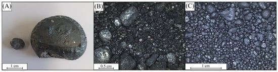
Figure 8.
Fractions of the samples FR-1-R3 (A), FR-2-R2 (B) and SR-1-R3 (C) recovered from the crucible after the furnace experiment.
In Figure 8C it is observed that spherical metallic particles were produced after the furnace experiment of sample FR-2, and the particle size ranged from 50 µm to 500 µm. However, aside from the spheres, a black matrix was found in the sample material. Metal fragments significantly smaller than 50 µm were observed inside of larger matrix particles. Both fractions showed a strong response to applied magnetic force; thus, magnetic separation was unable to separate the metal particles from the black matrix in the recovered material. The total weight of both fractions was determined as 91.1 g (57 wt.%) of the initial mass. One major difference between the two fractions was observed in their comminution behaviour (<63 µm), in which the black matrix tends to comminute more easily due to its brittle rheology compared to the more ductile metallic fraction. The ductile fraction accounted 62 wt.%, corresponding to 38.2 wt.% of the total recovery from the initial mass. The distribution of the Fe-species of the metal fractions is given in Table 8. For sample FR-1, 99.4 wt.% of total Fe was determined. Almost all the total Fe was identified as metallic Fe. Di- and trivalent Fe was detected at concentration levels below the limit of detection of the used methods. For SR-1, a total Fe content of 77.3 wt.% was determined, whereas 72.2 wt.% were assigned as metallic Fe. The di- and trivalent Fe-species abundances were 2.1 wt.% and 1.6 wt.% for sample SR-1, respectively. The obtained Fe-species from the metal fraction of sample FR-2 resulted in a total Fe concentration of 77.8 wt.%. Metallic Fe was determined to an abundance of 77.8 wt.%, while the other Fe-species showed concentrations not exceeding 0.1 wt.%, each. Thus, among all the Fe-species the metallic Fe was the most dominant.
Table 8.
Distribution of Fe-species of the metal fractions recovered from the MgO crucible after the furnace experiments.
In Table 9 and Table 10, further chemical parameters such as the trace and minor element compositions including the C and S contents in the metal fractions are given. On the one hand, the highest concentrations of trace metals, apart from Cu, were determined for the sample SR-1, in which Ca, P, Cr and V showed the highest enrichment across the sample set. Thereby, P and Ca were detected at the highest concentrations with values of approximately 10,000 mg/kg and higher, respectively. The concertation of Cu in sample SR-1 was determined to have the lowest concentration of 179 mg/kg among the entire sample set; on the other hand, copper concentrations in samples FR-1 and FR-2 were discovered at higher concentrations of 3000 mg/kg and 2673 mg/kg, respectively. A significant abundance of Ti was observed in samples SR-1 (568 mg/kg) and FR-2 (466 mg/kg). For Ti the lowest amount was detected in sample FR-1 with a concentration of 6 mg/kg. As minor constituents, C and S were detected particularly in the metal fraction of SR-1, with values of 8.4 wt.% and 0.5 wt.%. Regarding C abundance, FR-2 shows a value of 1.3 wt.%, whereas FR-1 showed lower concentrations of C as well as of S.
Table 9.
Elemental composition of trace elements and total S and C abundance of the recovered metal fractions.
Table 10.
Major element composition determined on the non-metallic fractions recovered from the crucible after the furnace experiments.
A simplified calculation approach for the product carbon footprint (PCF) of the agglomerates produced was applied to determine the CO2 footprint [23]. Only the associated material and energy flows are taken into account. The production of the respective agglomeration plants and plant components is not considered. In the PCF, the total amount of greenhouse gases (GHGs) emitted and removed from a product system during its life cycle is balanced. Not only CO2 is considered, but also the so-called Kyoto gases, such as nitrous oxide (N2O) or methane (CH4). The results are presented as CO2 equivalents in the SI unit kilogram or metric ton. The balancing follows the established “Scope 1, 2, and 3 emission categories”, which comprise the various direct and indirect emissions. The scopes are divided into direct, indirect and other emissions. Each category reflects the different sources of GHG emissions of the total emissions of a product system. The specific energy-related emissions (Scope 1 and 2) were calculated by multiplying the specific energy consumption by the corresponding emission factors (EF). The individual emission factors (Scope 1) for each fuel are determined from the C content, for example from fuel analysis data. The emissions caused using electrical energy (Scope 2) are calculated by multiplying the specific energy consumption by the corresponding emission factors of the German electricity mix. Scope 3 emissions are determined by offsetting the specific EF with additional relevant process parameters. For the ecological comparison, the specific emissions of the material used were considered in the form of the so-called CO2 backpack.
To calculate the specific and total emissions for comparing cementitious with organic binders, the relevant emission factors for the agglomerate production process were first determined. As the residual materials and additives (e.g., cellulose fibres) used are waste products that would be landfilled, an emission factor of 0 tCO2/t material can be assumed, as seen in Table 11.
Table 11.
Emission factors of the input materials (LCI from Umberto using database of ecoinvent V. 3.9.1, [23]).
4. Discussion
4.1. Mechanical Properties of the Agglomerates
Five significant variables were investigated regarding their influence on the mechanical properties of the agglomerates, namely the type of binder, the binder content, the fibre content, the stamp pressure and the drying conditions.
Figure 9 demonstrates the influence of the different starch types as binders on the cold compressive strength of agglomerates. When comparing the two starch types across equivalent compaction pressures (10, 20, and 40 N/mm2) for FR-1, the most significant difference was observed at 40 N/mm2. At this pressure, the wheat starch recipe (R3) showed a cold compressive strength 17.0 MPa higher than that of the potato starch recipe (R4). In contrast, for agglomerates with SR-1, its mean cold compressive strength decreased by up to 12.4 MPa when using wheat starch instead of potato starch at the lowest compaction pressure of 10 N/mm2. The influence of the different binders could not be demonstrated for the same amount of starch for material FR-2. Overall, the influence of the binder types cannot be sufficiently described based on the results, as there is no clear trend in the developed CCS of the investigated agglomerates. A similarly uncertain behaviour is observed for porosities determined by Hg-injection. Increasing compaction pressure does not necessarily result in lower porosities due to enhanced compaction. As exhibited by [15], porosity does not significantly affect the metallization of Fe-oxide (magnetite) within self-reduction agglomerates. Each agglomerate must possess sufficient permeability to permit the escape of reaction gases, thereby preventing disintegration caused by overpressure. In the furnace experiments, the disintegration of individual agglomerates was attributed to the melting-induced breakdown of reduced Fe. However, this study did not investigate the gas dynamics and temperature dependence of permeability. Such investigation will be essential, particularly in combination with hot compressive strength and reduction under load (RUL) experiments, prior to industrial-scale trials. Nevertheless, the permeability of individual agglomerates is unlikely to substantially affect the overall column permeability in industrial-scale shaft furnaces systems. In general, disintegration of agglomerates in the furnace column must be avoided, as agglomerate fragments can obstruct pathways for ascending gas. Designation may also occur for other reasons, such as insufficient hot compressive strength.

Figure 9.
Binder-residue recipes for the samples FR-1-R2, -3 and -4, SR-1-R1 and -3, FR-2-R1, -2, -7 and -8.
For the investigation of the influence of cellulose fibres, the pairs of FR-1-R2 and FR-1-R3, as well as FR-2-R1 and FR-2-R2, and FR-2-R7 and FR-2-R8 can be compared with each other, as these recipes have the same compositions and vary only in the cellulose-fibre content. For both binders as well as for nearly all the stamp pressures applied, the influence of higher fibre content generally exhibits positive effects and leads to an increase in the average cold-compressive strength. However, it is observed that this effect weakens when the stamp pressing pressure increases.
On the other hand, understanding the influence of the compaction pressure is challenging, since none of the sample groups investigated showed consistent trends in compressive strength development. Consequently, the impact of stamp pressure on agglomerate strength is less pronounced than anticipated. The drying conditions of agglomerates using starch as an organic binder significantly affected their rheological behaviour during CCS tests. As shown in the force–deformation curves (Figure 10), the oven-dried samples (105 °C) clearly exhibited higher stiffness and a distinct fracture point. Specifically, the group pressed at 40 N/mm2 displayed the minimum displacement, due to the higher compaction achieved during pressing. Moreover, the oven-dried samples exhibited brittle fracture behaviour when subjected to loads exceeding their mechanical limits. In contrast, the agglomerates dried at ambient temperature demonstrated significant plastic deformation, which is described as a ‘squeezing’ effect, without a well-defined failure point under continuous compressive loading. This indicates that the drying process modifies the structural state of the agglomerates, thereby influencing their rheological and mechanical properties.
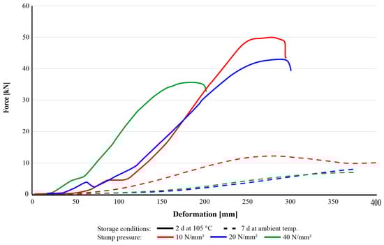
Figure 10.
Different behaviour of agglomerates (SR-1-R3) cured at room temperature for 7 d (dashed) and in a dry oven at 105 °C for 2 d.
The observed mechanical behaviour is attributed to the structural evolution of starch through the processes of gelatinization and retrogradation. These phenomena represent the key mechanisms for binder applications because, when starch molecules interact with water and are heated, they lose their crystallinity and become randomly ordered (gelatinization), thereby facilitating their penetration into the matrix material. Conversely, when starch is dehydrated and cooled down, the molecular state transitions into a more ordered and crystallized structure (retrogradation), eventually improving the mechanical rigidity of agglomerates [24]. In accordance with [18,24], different types of starch require temperatures between 60 °C and 80 °C to start the unfolding and hydrating processes in the presence of water in which the individual molecules can effectively disperse.
In this regard, the evaporation of excess water is the first step to initiate the retrogradation process. In the present study, starch was mixed with water, and dispersed using a mixer, without prior gelatinization. Furthermore, the retrogradation occurred during the curing of the agglomerates in the oven at 105 °C. It is still significantly lower than the starch decomposition temperature of at least 240 °C, as reported by [23]. However, the starch placed at room temperature does not undergo significant dehydration or retrogradation, which can explain the ductile behaviour observed during compression tests. Another test was carried out by [19] to investigate the effect of drying conditions on the mechanical properties of the agglomerate. The authors produced agglomerates by using pre-gelatinized starch in hot water and leaving them under an ambient condition to remove moisture inside until a constant weight was achieved. It was observed that, after drying for a couple of days, the CCS results showed average values of 7 MPa and 14 MPa when pressed at 20 and 40 N/mm2, respectively. These are notably lower than the CCS values exceeding 15 MPa achieved in this study under a similar stamping pressure of 40 N/mm2. This difference may originate from the distinct crystallization behaviour, resulting from the different starch-application methods. Further investigations of the starch crystallization within the intergranular volume may confirm various levels of intergrowth, particle attachment and starch crystallization.
As shown in Figure 11, agglomerates prepared with organic binders exhibited massive fungal growth after approximately one month of storage. Agglomerates dried under ambient conditions, following a similar methodology to that reported by [19], showed faster growth of mould within two weeks. As a result, although forced drying requires the higher energy consumption, it leads to an enhanced storage capability by removing moisture from the agglomerates. In addition, this heat treatment can promote the stability of the agglomerates, preventing microbial activity without using chemical fungicides.

Figure 11.
Agglomerates of the SR-1-R3 with intensive mould infestation (white) after several weeks of storage under ambient conditions.
4.2. Self-Reducing Properties of the Agglomerates
Figure 12, the residue materials employed in this study originated from varying steel and cast iron production processes. These materials consistently contain high amounts of Fe, primarily in the form of metallic Fe, hematite (Fe2O3), magnetite (Fe2+Fe3+2O4) and wüstite (FeO). Due to the distinct nature of the manufacturing routes, samples collected from the off-gas cleaning systems show significant variances in Fe-species abundance. In Figure 12, the distribution of Fe-species in the raw materials (A) and the magnetic fractions recovered from furnace experiments (B) were calculated against the total Fe content. Given the concentration of metallic Fe in this input material, the self-reducing properties of the agglomerates are not as important as for the other samples, FR-2 and SR-1.
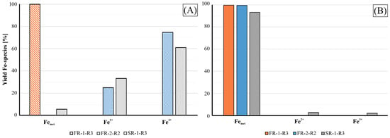
Figure 12.
Yield of the Fe-species across the samples FR-1, FR-2 and SR-1 (A) and of the magnetic and ductile fractions produced by the furnace experiment (B) in respect to the total Fe abundance.
For the FR-1 sample, metallic Fe serves as the dominant phase in both raw material and the recovered magnetic product. This is because the material is collected from the filter assembly of the final product treatment in a foundry, where the dust accumulates significant amounts of abraded metallic Fe fines from the processed products. This composition corresponds to the low amounts of trace metals in the magnetic product, with only Cu and Cr detected at a significant concentration level. The content of Cu is notably important since it acts as a promoter for the formation of graphite spherulites in nodular cast iron production. Other trace elements are generally detected in very low concentrations because, during the cupola furnace smelting, slagging agents are added to refine the crude iron before further treatment. Furthermore, volatile constituents such as K, Na and Zn undergo thermal volatilisation at high temperature and are subsequently lost to the off-gas stream. The initial C content in the raw material can be explained by the cast iron composition as well as by SiC (moissanite) abrasive agents used in cleaning facilities. The oxidic non-magnetic phase of the furnace product still retains minor quantities of residual Fe.
For the samples SR-1 and FR-2, the initial compositions of the Fe-species reflect the more oxidic nature of the products, characterized by the presence of magnetite and hematite as the major Fe bearing phases. Consequently, the self-reducing properties of these agglomerates are crucial for the recycling route via cupola or blast furnaces. Despite the high Fe content of 81 wt.% for SR-1 and 61 wt.% for FR-2, XRF analysis indicates that high Zn concentrations are likely to impede this refining route. Concretely, in these residues, Zn is found as Zn oxides (zincite) or as a substitutional element within the spinel lattice [8]. During the smelting process, Zn in these phases can be reduced to metallic Zn and evaporated above 900 °C. The gaseous Zn subsequently condenses on cooler areas of the furnace exhaust, causing operational problems such as clogging and accretion formation. This loss of Zn to the off-gas stream implies the lack of Zn in the furnace products of the samples SR-1 and FR-2. In addition, other trace metals such as Cu and P, aside from Cr, V and Ti, show accumulated concentrations in the metal phase, which is consistent with [25,26]. The latter group of elements is not critical for the steelmaking process since those metals are commonly observed in a variety of Fe ores in comparable or even higher amounts. For instance, ores from iron oxide–apatite (IOA) deposits in Sweden and Iran typically contain these elements as well [27]. These elements can therefore be easily removed from pig iron through state-of-the-art processes such as oxygen blowing in the BOF stage. On the other hand, copper represents an important impurity in steel production as it negatively affects the mechanical properties of steel. Furthermore, it is challenging to remove Cu from steel or pig iron during refining [28]. Therefore, Cu and Zn are two main factors for the maximum internal recycling rate of the SR-1-R3 and FR-2-R2 materials. Nevertheless, such Cu-containing agglomerates can be incorporated in foundries, as explained for the sample FR-1 beforehand.
Regarding the distribution of Fe fractions, the magnetic and ductile products from the furnace experiments indicate that both samples are highly enriched in metallic Fe, as seen in Figure 12, confirming the successful reduction of the iron oxides. Nevertheless, the oxidic fractions of FR-2-R2 and SR-1-R3 still contain significant amounts of Fe and C, as shown in Table 10. In the case of SR-1, a residual Fe content of 11.5 wt.% was coupled with significant C enrichment up to 31 wt.%. This indicates that the metal and oxidic fractions were intergrown, making it difficult for the manual separation through sieving and magnetic sorting to achieve complete phase separation. Therefore, further comminution and application of laboratory-scale magnetic separators are required for enhanced separation. The reduction efficiency is proven by the distribution of the Fe-species in the non-metallic fraction in which metallic Fe is the dominant species aside from the Fe+2 and Fe+3 present in minor amounts of magnetite; see the lower XRD pattern in Figure 13.
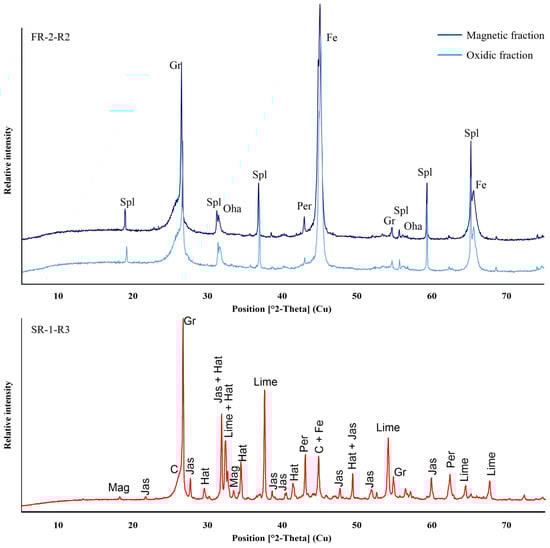
Figure 13.
XRD patterns of slag and metal fractions of sample FR-2-R2 (upper) and SR-1-R3 (lower) recovered after reduction tests using Tamman furnace. Interpreted diffraction patterns indicate similar mineral assemblage for both fractions consisting of graphite (Gr), amorphous carbon (C), spinel-group (Spl/Mag), oldhamite (Oha), periclase (Per), hatrutite (hat), jasmundine (jas), magnetite (mag) and metallic Fe (Fee).
Other elements, such as Ca, Si, and Mg, remained in the oxidic state regardless of the reducing environment. In Figure 13, the mineralogical composition of oxidic phases from SR-1-R3 (red) and FR-2-R2 (blue) as well as of the metal fraction of FR-2-R2 (dark blue) are displayed via XRD patterns. For SR-1-R3, only minor amounts of magnetite were detected, with metallic Fe as the predominant iron phase. The XRD peaks identified as calcium silicates, such as hatrurite and jasmundine, together with periclase (MgO) and lime (CaO) are consistent with the raw material composition. The presence of the MgO phase is likely derived from the MgO crucible through dissolution and erosion, or from mechanical attachment during sample retaining from the furnace experiment. Similarly, XRD analysis of the FR-2 oxidic fraction exhibits that both magnetic and oxidic fractions are composed of the same mineralogical composition, with metallic Fe as the dominant phase.
Carbon content in the oxidic fractions was primarily detected as graphite (Gr) and amorphous carbon (C), as demonstrated in Figure 13. The observed excess C in the oxidic fraction of SR-1-R3 highlights the necessity to optimize the mass balance of the reaction with respect to C consumption and the selection of alternative reducing agents. Lowering the carbon content and substituting fossil carbon with biochar may offer a potential strategy to reduce the CO2-footprint. Carbon release and reduction processes are expected to result in distinct gas emissions, which rely on the agglomerate composition and temperature-dependent reactions. Firstly, organic constituents release CO, CO2, CH4, H2O, and higher hydrocarbons due to thermal dehydration and decomposition of the starch ((C6H10O5)n) binder and the cellulose (C12H20O10) fibres. At elevated temperatures, CO2 is further released as a result of reduction of the Fe-oxide phases, as described in samples FR-2 and SR-1. Heating microscopy results presented in this study indicate that these reactions occur at approximately 1221 °C for FR-2 and 1288 °C for SR-1, respectively. Quantification of C consumption during the reduction experiments requires comprehensive analysis using thermogravimetric analysis (TGA) and/or off-gas composition monitoring to correlate C release with its associated reactions, such as gasification of C by CO2 formation, and hydrocarbon release linked with temperature. However, the off-gas system of the Tammann furnace used in the experiments does not allow gas monitoring with sufficient precision and therefore detailed data on excess gases was not recorded.
4.3. Ecological Evaluation of the Agglomerates
The emission factor for cementitious binders and organic biogenic binders as well as the specific emission comparison per ton of agglomerate for the two binder systems can be found in Table 12. As the overall binder content for organic binders as well as the EF is significantly lower than that of organic biogenic binders, the use of this specific binder system is therefore more sustainable, even taking into account the process chain such as mixing or the use of the hydraulic press.
Table 12.
Emission factors for different binders.
For further comparison in terms of the ecological assessment of the produced agglomerates, the EF as well as the specific emissions per tonne of potential iron content for the use of pig iron and iron ore can be found in Table 13. For all the agglomerates considered, lower specific emissions can be derived per metallic iron applied than for the use of pig iron. For the use of the agglomerates instead of primary iron ore for an integrated steel plant and an electric steel plant, the savings of CO2 emissions depend on the total content of agglomerates. The savings heavily depend on what raw material will be substituted with the secondary iron carriers. Nevertheless, the practical savings should be evaluated based on the amount of recoverable metal achieved from the agglomerates themselves. In the case of full iron recovery from the residues, the savings would be much higher than with lower iron recovery (e.g., partial or incomplete reduction of the iron contained in the residues).
Table 13.
Emission factors for different sources of iron (based on own calculations).
5. Conclusions
In this work, the agglomeration and applicability for pyrometallurgical Fe extraction of three different residues from the steel and cast-iron industry were investigated. For each of these materials, recipes with different mixture proportions of starch, coke, and fibres were prepared and examined on a laboratory scale. The manufactured agglomerate bricks were therefore tested in accordance with different key parameters for their application in Fe-recycling:
- Portland cement was successfully replaced by starch binders resulting in cold compressive strength always exceeding the lower limit of 5 MPa. Thus, the produced agglomerates were proven to be stable for onsite handling and storage after curing.
- By utilizing organic binders, the specific emissions of produced agglomerates for Fe-recycling could be decreased by factor 4.5 in comparison to cement bound agglomerates
- Forced curing of the produced agglomerates was figured out to be the most significant factor controlling the rheology of the produced agglomerates regarding the binder reaction in the desired temperature range.
- Adding cellulose fibres tends to increase the compressive strength of agglomerates. The origin of the applied different starches, however, tends not to have any significant influence.
- For all surveyed agglomerates and compaction pressures, sufficient porosity was determined to be >21.5% enabling the potential utilization in shaft furnace systems in which gas permeability is of high importance.
- The differences between the residues’ mineralogical and chemical composition, the particle size distribution and the applied compaction force tend to not significantly influence the agglomerate strength when using binder-supported stamp press agglomeration
- For all tested materials, satisfactory reduction and melting behaviour was proven in the lab-scale experiments.
Thus, it was proven by this study that starch binders in combination with stamp press agglomeration can produce agglomerates of acceptable quality for internal and environmentally sound Fe-recycling. Furthermore, the universal application of the development process was figured out by the utilization of different types of typical residues of steel plants and of mixed residues from cast iron foundries. From the results, it can be concluded that individual recipe development must take place also in respect to the different materials investigated. Despite the sometimes very similar physical and chemical properties of the materials, it is hardly possible to derive any regularity according to which a recipe could be used without prior verification. Using cellulose fibres and starch as binder, agglomerates can be produced by stamp press compaction, which features a significant decrease in the CO2 footprint through the complete replacement of Portland cement binder.
Furthermore, the substitution of the used fossil-based reduction agents by biogenic C will result in a near-zero-emission process for Fe-recycling of different residues from the iron and steelmaking industry. Considering the low cost and the high level of variability, the developed method is also a suitable process for smaller-scaled facilities producing lower quantities of several types of residues. Another topic for further research will be the substitution of starches by other by-products or wastes like tar and wood liquor produced during pyrolysis processes using organic waste as educt for biochar and biogas (H2, CH4) production. Nowadays, these types of waste are disposed by incineration which recovers only the caloric value.
Author Contributions
Conceptualization, L.H.G., C.G. and P.D.; methodology, L.H.G., C.G., Y.L., T.W. and P.D.; validation, V.F., T.E. and C.W.; investigation L.H.G., C.G., Y.L. and T.W.; data curation, Y.L.; writing—original draft preparation, L.H.G., C.G. and Y.L.; writing—review and editing, L.H.G., C.G., Y.L., V.F., T.E., P.D. and C.W.; visualization, L.H.G., C.G. and Y.L.; supervision, T.E., P.D. and C.W.; project administration, P.D. and C.W. All authors have read and agreed to the published version of the manuscript.
Funding
The research project ReMPA4S (FKZ: 21146 N) was financially supported by the German Federal Ministry for Economic Affairs and Climate Action via the IGF program.
Data Availability Statement
The original contributions presented in this study are included in the article. Further inquiries can be directed to the corresponding author(s).
Acknowledgments
F. Meyer, D. Ebert, L. Faber and A. Bertzen of the staff of the FEhS-Institute are gratefully acknowledged for their attendance during the XRD, XRF and CCS measurements and conducting furnace experiments. The authors further show gratitude to P. Thelen of the Hüttenwerk Krupp Mannesmann F&E Division for supporting the project with reduction agent as well as for his always kind advice and discussion during the project.
Conflicts of Interest
Author TW is now employed by the company Deutsche Rockwool GmbH. The remaining authors declare that the research was conducted in the absence of any commercial or financial relationships that could be construed as a potential conflict of interest.
Appendix A
Appendix A.1. Porosity Data Determined by Hg-Porosimeter for the 3 Different Compaction Pressures of the Sample FR-1-R3
| 10 N/mm2 | 20 N/mm2 | 40 N/mm2 | ||||
| Medium Point | Porosity | Porosity | Porosity | |||
| (nm) | % | cum. % | % | cum. % | % | cum. % |
| 75,000 | 0.0 | 0.0 | 0.0 | 0.0 | 0.1 | 0.1 |
| 37,500 | 0.4 | 0.5 | 0.5 | 0.5 | 0.7 | 0.8 |
| 16,250 | 1.1 | 1.5 | 1.2 | 1.7 | 2.1 | 2.8 |
| 5250 | 1.9 | 3.4 | 1.7 | 3.4 | 2.3 | 5.1 |
| 2000 | 7.0 | 10.4 | 6.7 | 10.1 | 5.6 | 10.7 |
| 650 | 8.5 | 18.9 | 7.2 | 17.3 | 6.0 | 16.7 |
| 200 | 2.6 | 21.5 | 2.2 | 19.6 | 2.6 | 19.3 |
| 65 | 1.4 | 22.9 | 1.6 | 21.1 | 1.6 | 20.8 |
| 20 | 1.1 | 24.0 | 0.7 | 21.8 | 0.6 | 21.5 |
| 8.75 | 0.3 | 24.3 | 0.2 | 22.0 | 0.2 | 21.6 |
| 5.6 (total) | 0.0 | 24.3 | 0.0 | 22.0 | 0.0 | 21.7 |
Appendix A.2. Porosity Data Determined by Hg-Porosimeter for the 3 Different Compaction Pressures of the Sample FR-2-R2
| 10 N/mm2 | 20 N/mm2 | 40 N/mm2 | ||||
| Medium Point | Porosity | Porosity | Porosity | |||
| [nm] | % | cum. % | % | cum. % | % | cum. % |
| 75,000 | 0.2 | 0.2 | 0.1 | 0.1 | 0.1 | 0.1 |
| 37,500 | 2.2 | 2.4 | 1.8 | 1.9 | 2.8 | 2.9 |
| 16,250 | 15.9 | 18.3 | 12.5 | 14.4 | 14.5 | 17.4 |
| 5250 | 10.8 | 29.1 | 10.6 | 25.0 | 9.2 | 26.7 |
| 2000 | 4.6 | 33.7 | 6.4 | 31.5 | 6.3 | 33.0 |
| 650 | 1.3 | 35.0 | 1.5 | 33.0 | 1.8 | 34.8 |
| 200 | 0.5 | 35.5 | 0.7 | 33.7 | 0.7 | 35.5 |
| 65 | 0.3 | 35.8 | 0.5 | 34.2 | 0.4 | 35.9 |
| 20 | 0.3 | 36.2 | 0.4 | 34.6 | 0.3 | 36.2 |
| 8.75 | 0.1 | 36.3 | 0.2 | 34.8 | 0.1 | 36.4 |
| 5.6 (total) | 0.0 | 36.3 | 0.0 | 34.8 | 0.0 | 36.4 |
Appendix A.3. Porosity Data Determined by Hg-Porosimeter for the 3 Different Compaction Pressures of the Sample SR-1-R3
| 10 N/mm2 | 20 N/mm2 | 40 N/mm2 | ||||
| Medium Point | Porosity | Porosity | Porosity | |||
| [nm] | % | cum. % | % | cum. % | % | cum. % |
| 75,000 | 0.2 | 0.2 | 0.1 | 0.1 | 0.2 | 0.2 |
| 37,500 | 1.8 | 1.9 | 1.7 | 1.8 | 2.3 | 2.6 |
| 16,250 | 3.6 | 5.5 | 3.8 | 5.6 | 4.5 | 7.1 |
| 5250 | 4.8 | 10.4 | 3.9 | 9.5 | 4.2 | 11.3 |
| 2000 | 8.1 | 18.4 | 7.1 | 16.6 | 6.1 | 17.4 |
| 650 | 7.5 | 25.9 | 8.2 | 24.8 | 6.9 | 24.3 |
| 200 | 11.0 | 36.9 | 14.0 | 38.8 | 11.9 | 36.2 |
| 65 | 2.0 | 38.9 | 2.2 | 41.0 | 1.5 | 37.7 |
| 20 | 0.9 | 39.9 | 0.5 | 41.5 | 0.6 | 38.4 |
| 8.75 | 0.3 | 40.1 | 0.1 | 41.6 | 0.2 | 38.6 |
| 5.6 (total) | 0.0 | 40.1 | 0.0 | 41.6 | 0.0 | 38.6 |
References
- Gronen, L. Aufkommen und Verbleib von Stäuben, Schlämmen und Walzzunder in der Eisen- und Stahlindustrie—Ergebnisse und Schlussfolgerungen der Staubumfrage 2020. In Report—Wissenschaftsprojekte des FEhS-Instituts; FEhS-Institut für Baustoff-Forschung e.V.: Duisgurg, Germany, 2022; Volume 2, pp. 13–17. [Google Scholar]
- Drissen, P. Aufkommen und Verbleib von Stäuben, Schlämmen und Walzzunder der Eisen- und Stahlindustrie—2018. In Report—Wissenschaftsprojekte des FEhS-Instituts; FEhS-Institut für Baustoff-Forschung e.V.: Duisgurg, Germany, 2019. [Google Scholar]
- Pöllmann, H.; Snellings, R.; Valentini, L. Cement and Concrete—Past, Present, and Future. Elements 2022, 18, 295–299. [Google Scholar] [CrossRef]
- Mombelli, D.; Gonçalves, D.L.; Mapelli, C.; Barella, S.; Gruttadauria, A. Processing and Characterization of Self-Reducing Briquettes Made of Jarosite and Blast Furnace Sludges. J. Sustain. Metall. 2021, 7, 1603–1626. [Google Scholar] [CrossRef]
- Lemos, L.R.; da Rocha, S.H.F.S.; de Castro, L.F.A.; Assunção, G.B.M.; da Silva, G.L.R. Mechanical strength of briquettes for use in blast furnaces. REM Int. Eng. J. 2019, 72, 63–69. [Google Scholar] [CrossRef]
- Gronen, L.; Gondorf, C.; Mild, L.; Algermissen, D.; Echterhof, T.; Pfeifer, H. Sustainable metal (Fe) recovery using stamp press bricks made of dusts and sludges from iron and steel making processes. In Book of Abstracts—GeoMinKöln 2022 11–15 September 2022; RWTH Publications: Aachen, Germany, 2022. [Google Scholar]
- Holtzer, M.; Kmita, A.; Roczniak, A. The recycling of materials containing iron and zinc in the OxyCup Process. Arch. Foundry Eng. 2015, 15, 126–130. [Google Scholar]
- Antrekowitsch, J.; Steinlechner, S.; Unger, A.; Rösler, G.; Pichler, C.; Rumpold, R. Zinc and Residue Recycling; Elsevier: Amsterdam, The Netherlands, 2014; pp. 113–124. [Google Scholar]
- Narita, C.Y.; Mourao, M.B.; Takano, C. Development of composite briquettes of iron ore and coal hardened by heat treatment. Ironmak. Steelmak. 2014, 42, 548–552. [Google Scholar] [CrossRef]
- Bizhanov, A.; Chizhikova, V. Agglomeration in Metallurgy; Springer International Publishing: Berlin/Heidelberg, Germany, 2020. [Google Scholar]
- Drissen, P.; Algermissen, D.; Abel, R. Industrielle Verfestigung und Recycling von Schlämmen aus Nassenstaubungsanlagen der Eisen- und Stahlindustrie. In Report—Wissenschaftsprojekte des FehS; FEhS-Institut für Baustoff-Forschung e.V.: Duisgurg, Germany, 2019. [Google Scholar]
- Willms, T.; Echterhof, T.; Steinlechner, S.; Aula, M.; Abdelrahim, A.; Fabritius, T.; Mombelli, D.; Mapelli, C.; Preiss, S. Investigation on the Chemical and Thermal Behavior of Recycling Agglomerates from EAF by-Products. Appl. Sci. 2020, 10, 8309. [Google Scholar] [CrossRef]
- Echterhof, T.; Willms, T.; Preiss, S.; Aula, M.; Abdelrahim, A.; Fabritius, T.; Mombelli, D.; Mapelli, C.; Steinlechner, S.; Unamuno, I. Fabrication of Agglomerates from Secondary Raw Materials Reinforced with Paper Fibres by Stamp Pressing Process. Appl. Sci. 2019, 9, 3946. [Google Scholar] [CrossRef]
- Vitikka, O.; Iljana, M.; Heikkilä, A.; Tkalenko, I.; Koriuchev, N.; Shehovsov, D.; Malkki, A.; Fabritius, T. Suitability of Auger Pressing Briquettes for Blast Furnace Use Based on Laboratory Tests. Minerals 2022, 12, 868. [Google Scholar] [CrossRef]
- Ignacio, I.; Brooks, G.; Pownceby, M.I.; Rhamdhani, M.A.; Rankin, W.J. Effects of sintering conditions on porosity, strength, and reducibility of hematite and magnetite tablets. In Proceedings of the IMPC Asia-Pacific 2022, Melbourne, Australia, 22–24 August 2022. [Google Scholar]
- Benk, A.; Coban, A. Molasses and air blown coal tar pitch binders for the production of metallurgical quality formed coke from anthracite fines or coke breeze. Fuel Process. Technol. 2011, 92, 1078–1086. [Google Scholar] [CrossRef]
- Schubert, H. Grundlagen des Agglomerierens. Chem. Ing. Tech. 1979, 51, 266–277. [Google Scholar] [CrossRef]
- Steele, R.B.; Bizhanov, A.P. Stiff extrusion agglomeration of arc furnace dust and ore fines for recovery at a ferro alloy smelter. In Proceedings of the 32nd Biennial Conference of the Institute of Briquetting and Agglomeration 2011, New Orleans, LA, USA, 25–28 September 2011; Curran: Red Hook, NY, USA, 2013; pp. 41–53. [Google Scholar]
- Akshit, F.N.U.; Poswal, V.; Kaushik, R.; Deshwal, G.K.; Huppertz, T. Influence of Starch on the Rheological, Textural, and Microstructural Properties of Processed and Analogue Cheeses. Encyclopedia 2025, 5, 41. [Google Scholar] [CrossRef]
- Mohd, N.A.; Amini, M.H.; Masri, M.N. Propertis and Characterization of Starch as a Natural Binder: A Brief Overview. J. Trop. Resour. Sustain. Sci. 2016, 4, 117–121. [Google Scholar]
- Dall’Osto, G.; Mombelli, D.; Trombetta, V.; Mapelli, C. Effect of Particle Size and Starch Gelatinization on the Mechanical and Metallurgical Performance of Jarosite Plus Blast Furnace Sludge Self-Reducing Briquettes. J. Sustain. Metall. 2024, 10, 759–774. [Google Scholar] [CrossRef]
- Echterhof, T.; Willms, T.; Preiß, S.; Omran, M.; Fabritius, T.; Mombelli, D.; Mapelli, C.; Steinlechner, S.; Unamuno, I.; Schüler, S.; et al. Developing a new process to agglomerate secondary raw material fines for recycling in the electric arc furnace—The Fines2EAF project. La Metall. Ital. 2019, 5, 31–40. [Google Scholar]
- Pietsch, W. Agglomeration Processes. Phenomena, Technonolgies, Equipment; Wiley-VCH Verlag GmbH: Hoboken, NJ, USA, 2001. [Google Scholar]
- Müller, W. Mechanische Grundoperationen und ihre Gesetzmäßigkeiten; Müller, W., Ed.; Oldenbourg Verlag: München, Germany, 2008; pp. 165–233. [Google Scholar]
- Ecoinvent Association. Ecoinvent Data Version 3.9.1; Ecoinvent Association: Zürich, Switzerland, 2025. [Google Scholar]
- Kadam, S.U.; Tiwari, B.K.; O’Donnell, C.P. Improved thermal processing for food texture modification. In Modifying Food Texture; Elsevier: Amsterdam, The Netherlands, 2015; pp. 115–131. [Google Scholar]
- Liu, X.; Wang, Y.; Yu, L.; Tong, Z.; Chen, L.; Liu, H.; Li, X. Thermal degradation and stability of starch under different processing conditions. Starch Stärke 2012, 65, 48–60. [Google Scholar] [CrossRef]
- Ellingham, H.J.T. Reducibility of oxides and sulphides in metallurgical processes. J. Soc. Chem. Ind. 1944, 63, 125–160. [Google Scholar]


Disclaimer/Publisher’s Note: The statements, opinions and data contained in all publications are solely those of the individual author(s) and contributor(s) and not of MDPI and/or the editor(s). MDPI and/or the editor(s) disclaim responsibility for any injury to people or property resulting from any ideas, methods, instructions or products referred to in the content. |
© 2026 by the authors. Licensee MDPI, Basel, Switzerland. This article is an open access article distributed under the terms and conditions of the Creative Commons Attribution (CC BY) license.