Abstract
In this study, a finite element simulation model for the nosing of the non-disengagement fastening device’s 2A12 aluminum alloy-spacing shim was established. Furthermore, the effects of the fillet radius, inclination angle, and stamping velocity of the nosing die on the formation of the spacing shim were examined. The following conclusions were drawn. (1) The die’s fillet radius primarily affects the spacing shim’s bending angle—as the die’s fillet radius increases, the bending performance decreases and meets the requirement when the fillet radius is 1.8 mm. (2) The die’s inclination angle affects the spacing shim’s nosing dimension: the nosing dimension increases with the increase in the die’s inclination angle and is optimal when the die’s inclination angle reaches 7°. (3) Within the range of 186–294 mm/s, the stamping velocity barely affects the formation of the spacing shim.
1. Introduction
In aerospace field, aluminum alloy is the most widely used light alloy. As one of the most widely used Al-Cu-Mg alloys [,], 2A12 aluminum alloy is a hard aluminum material with good plasticity and formability and is commonly used in satellite structures and various spacecrafts []. As a standalone connection unit on spacecrafts, a non-disengagement fastening device has numerous advantages, including non-disengagement performance at all stages, locking, reliable connection, repeatable operation, lightweight, and no redundant risk []. However, high requirements are imposed on the non-disengagement fastening devices’ performance and surface quality, and the nosing of their spacing shims is the most challenging step in the manufacturing process. Peng Liufeng [] obtained qualified forgings using DEFORM-3D software to numerically simulate the formation of 2A12 aluminum alloys. Li Qingjun [] studied the material and die temperatures, lubrication, and nosing velocity and achieved the hot shell nosing of 6351 aluminum alloy gas cylinders that can cost-effectively replace the multiple cold extrusion nosing process. To address the spinning accuracy and thermal deformation issues of thin-walled aluminum alloy shells, Guo Yaming [] studied the power spinning process for thin-walled 2A12 aluminum alloy shells and could control the shapes, dimensions, and mechanical performance of the parts by combining the abovementioned process with heat treatment.
The sheet metal stamping process has been widely investigated by developing finite element models in the literature [,,,,,]. In this study, we used ABAQUS 2021, a finite element simulation software, to establish a simulation model for the nosing of 2A12 aluminum alloy spacing shims, examined the fillet radius’ effects and the inclination angle of the die and stamping velocity on the bending size, shape, stress, strain, and displacement during the spacing shim’s nosing, and designed and optimized key dimensions of the die to guide its design and assembly processes.
2. Finite Element Analysis of Spacing Shim Nosing
2.1. Establishment of the Finite Element Model
As shown in Figure 1, the stamping model for the non-disengagement fastening device’s spacing shim comprises a nosing die, spacing shim, and fixed die. The spacing shim is 22 mm in height and up to 16 mm in external diameter. The rigidity of the nosing and fixed die is considerably higher than that of the spacing shim, and thus they are hardly deformable. Therefore, the nosing and fixed die were defined as discrete rigid bodies, while the spacing shim was defined as a deformable object.
Figure 1.
Finite element model for the spacing shim’s nosing. a—Nosing die; b—spacing shim; c—fixed die. (Unit: mm).
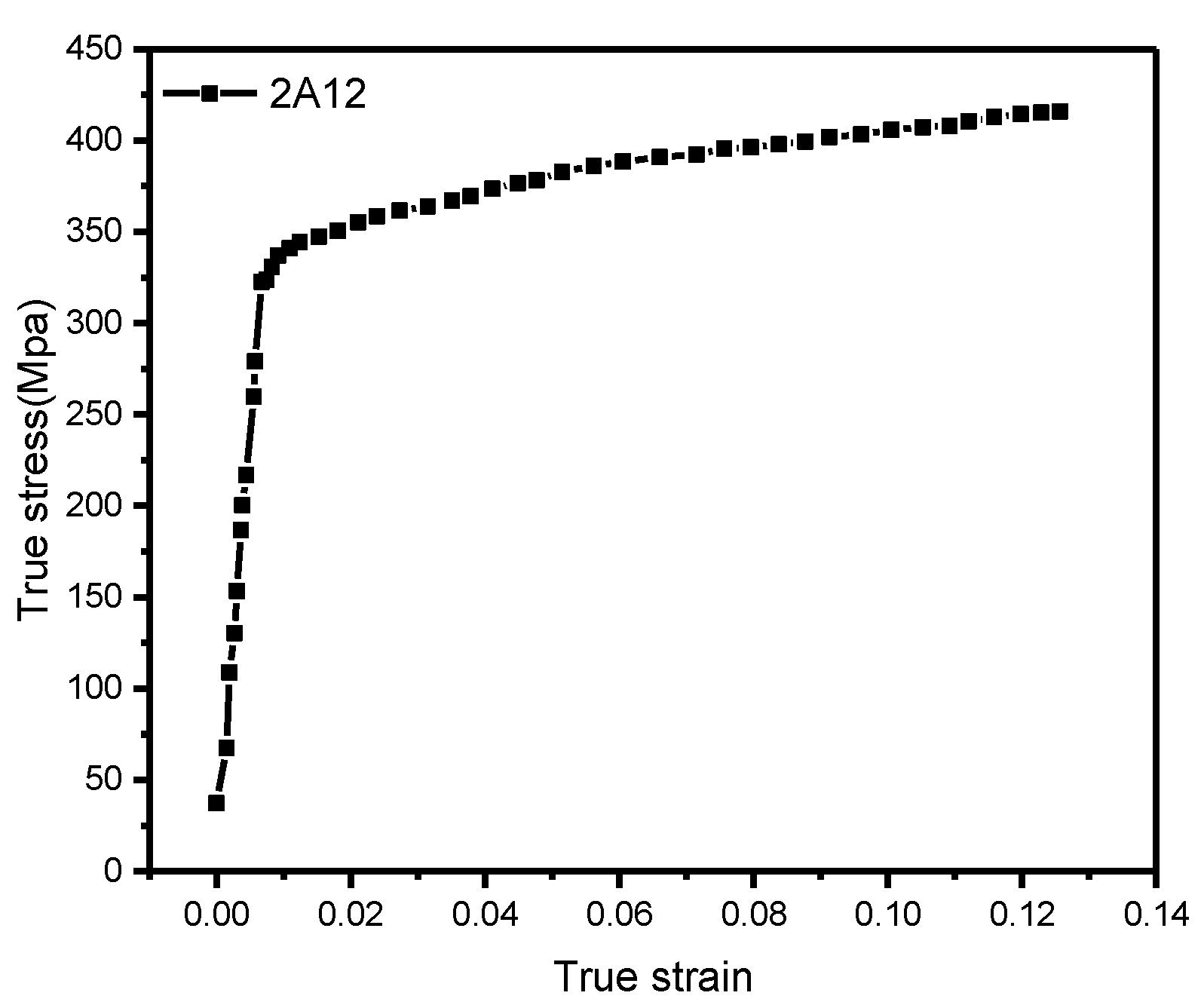
2.2. Material Properties
The spacing shim of the non-disengagement fastening device comprises 2A12 aluminum alloy, whose primary specifications are listed in Table 1. Figure 2 shows the actual stress–strain curve of the material derived from the test.
Table 1.
Main material properties of the 2A12 aluminum alloy.
Figure 2.
Actual stress–strain curve of the 2A12 aluminum alloy.
The spacing shim yields and deforms plastically under external load, and follows the Mises yield criterion in the finite element simulation [,]:
where σs is the yield stress;
is the deviator stress tensor; σij is the stress tensor; σmδij is the spherical stress tensor;
is the average normal stress; δij is the unit tensor; and
where
where is the equivalent stress and J2 is the second stress tensor; x represents the extrusion direction of the material; and y and z represent the normal directions of the material.
The simulation computations in this study followed the Mises yield criterion.
2.3. Gridding
The cell size is closely related to the accuracy of analysis and has considerable effects on the node stress and displacement. Table 2 illustrates the cell quantity and equivalent stress for different cell sizes. For a cell size of 0.15 mm, the equivalent stress tended to be smooth and a small cell size did not significantly enhance the accuracy. Thus, the cell size was set to 0.15 mm.
Table 2.
Gridding and equivalent stress.
2.4. Defining Contacts and Boundary Conditions
Contacts between various surfaces are defined as “surface-to-surface contact” in the proposed model. The nosing die of high rigidity is defined as the master surface, while the slave surfaces are the side and top of the spacing shim of low rigidity. The nosing die and spacing shim are subjected to relative displacement, and their contact is defined as finite slip. The master surface is the fixed die of high rigidity, while the bottom of the spacing shim of low rigidity is defined as the slave surface. The fixed die and the spacing shim are not subjected to relative displacement and their contact is defined as a small slip.
The fixed die is fully fixed and the nosing die is moved downward at a specified speed to deform the spacing slim through pressure.
2.5. Requirements and Process Parameters for Stamping
Upon the completion of the spacing shim’s stamping, the edge on its top is straight and smooth without any scratch on the surface, wrinkling [,], or crack, and the one-side nosing dimension is 2.4 ± 0.05 mm.
The nosing die’s dimensions directly influence the forming of the spacing shim. As shown in Figure 3, the key dimensions of the die are fillet radius (R) and inclination angle (α). The stamping velocity (v) may affect the forming performance. In this study, we examined the forming of the spacing shim from viewpoints of R, α, and v by simulating the effect of each parameter on the analysis result. The values of R, α, and v are as follows: R = 1.2, 1.5, 1.8, 2.1, and 2.4 mm; α = 1°, 4°, 7°, 10°, and 15°; v = 186, 213, 240, 266, and 294 mm/s.
Figure 3.
Key dimensions of the nosing die. a—Fillet radius of the die (R); b—Inclination angle of the die (α). (Unit: mm).
3. Simulation Result Analysis
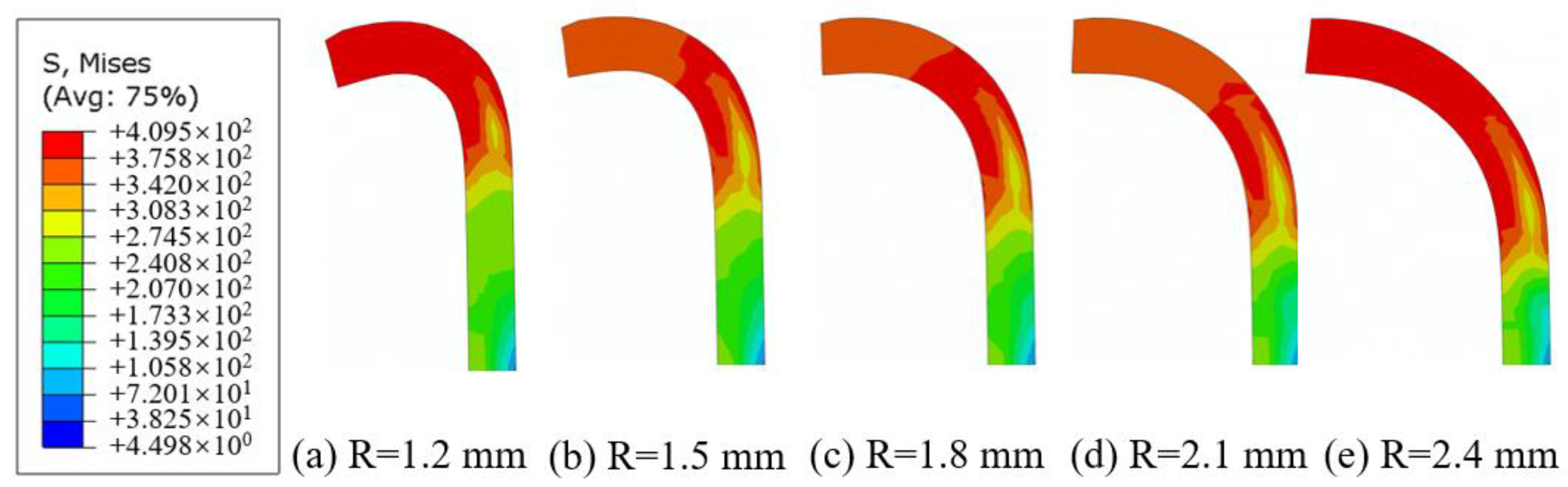
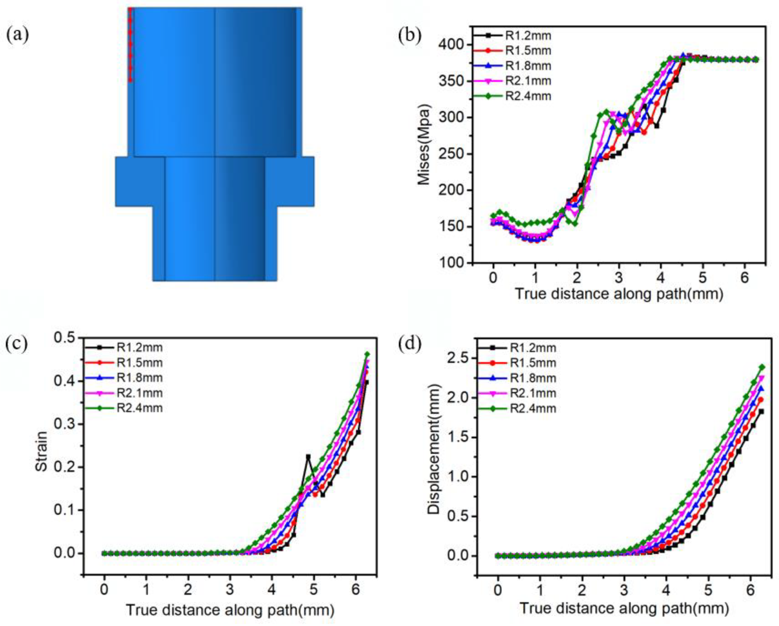
3.1. Effect of Nosing Die’s Fillet Radius on the Forming Performance
Figure 4 illustrates the nosing of the spacing shim with α = 1°, v = 186 mm/s, and R = 1.2, 1.5, 1.8, 2.1, and 2.4 mm. As the inclined angle is very small, the deformation of the spacing shim is mainly affected due to the die fillet, which bends the spacing shim. The bending radius of the spacing shim increases with the die’s fillet radius. With R = 1.2 mm, the spacing shim edges were not straight and bent downwards; with R = 1.5 mm, the spacing shim edges bent downwards, but to a lesser degree than they did with R = 1.2 mm; with R = 1.8 mm, spacing shim edges tended to be straight and the forming performance was rational; the horizontal spacing shim edges were short with R = 2.1 mm, while the arc spacing shim edges were long, and the bending performance was poor; with R = 2.4 mm, all edges were arc ones. As the nosing die’s fillet radius (R) increased, the horizontal spacing shim edges’ lengths decreased, while the arc edges increased. We concluded that, with the fillet radius R = 1.8 mm, the spacing shim nosing was smooth and straight with high performance; with R = 1.2 and 1.5 mm, the spacing shim bent greatly with non-smooth and downward-bent edges; with R = 2.1 and 2.4 mm, the horizontal edges were too long and the arc ones were too short, which failed to meet the requirements.
Figure 4.
Effect of nosing die’s fillet radius on stamping.
A path covering the primary deformation points on the spacing shim was generated, and values of equivalent stress, equivalent plastic strain, and radial displacement of these nodes on the path were extracted to develop an in-depth understanding of the stress, strain, and displacement of the deformation points during the spacing shim’s stamping (Figure 5a).
Figure 5.
Effect of nosing die’s fillet radius (R) on the equivalent stress (b), equivalent plastic strain (c), and radial displacement (d) of different points on the path (a).
Figure 5b illustrates the values of stress at different nodes on the spacing shim path under the different values of nosing die’s fillet radius (R). Values of stress at the same node on the path under different values of R were consistent and so were the stress curves. Figure 5c illustrates the equivalent plastic strain’s values at different nodes on the spacing shim path under different values of R. The values of equivalent strain increased significantly at some nodes with R = 1.2 and 1.5 mm, and their plastic deformation was uneven. A drastic increase in equivalent plastic strain should be avoided as it may lead to failure and cracking of the material. With nosing die’s fillet radius (R) = 1.8, 2.1, and 2.4 mm, the equivalent plastic strain curves were smooth and the forming performance was high. Figure 5d illustrates the values of radial displacement at various nodes on the spacing shim path under different values of R. As R increased, the radial displacement gradually increased. We concluded from the above analysis that R = 1.8 mm is the ideal fillet radius.
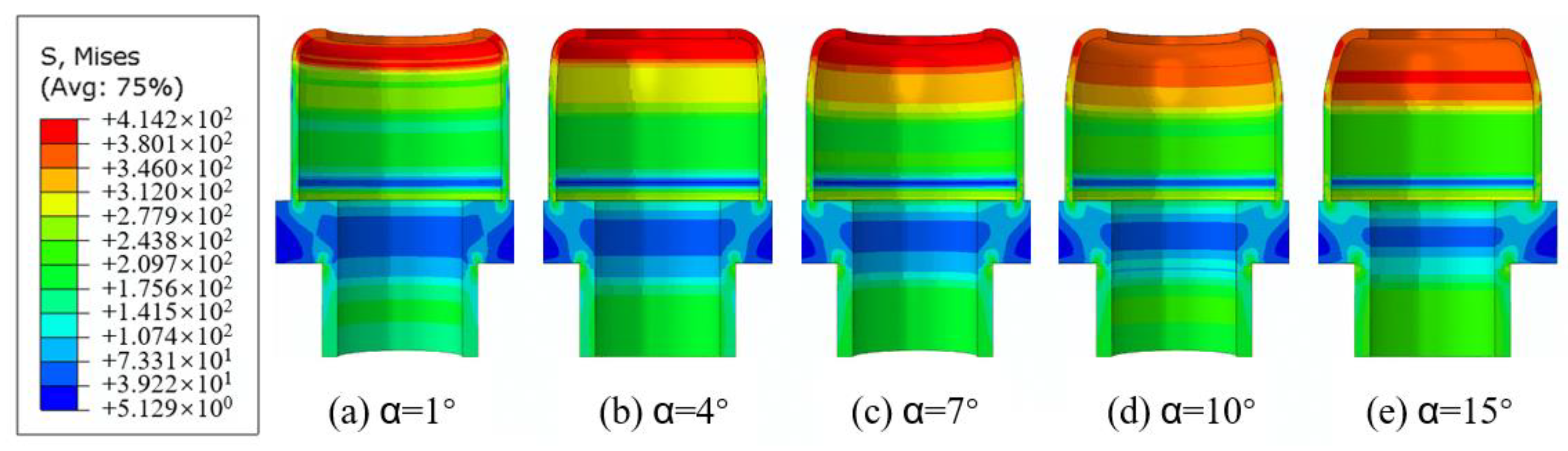
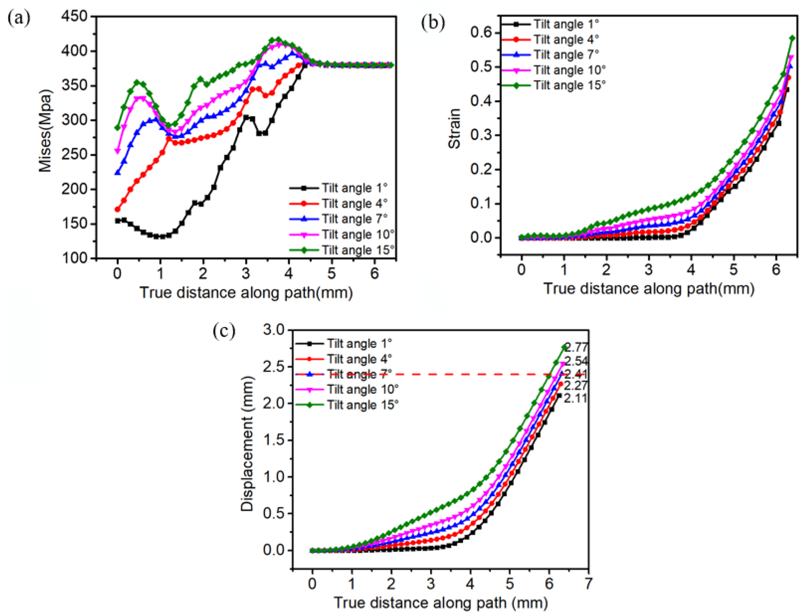
3.2. Effect of Nosing Die’s Inclined Angle (α) on the Forming Performance
With a nosing die’s fillet radius (R) = 1.8 mm and v = 186 mm/s, the spacing shim’s nosing with α = 1°, 4°, 7°, 10°, and 15° was simulated. An increase in the die’s inclined angle would increase the upper inclined angle of the spacing shim, but would not affect its bending angle on the whole. As illustrated in Figure 6, α directly affected the nosing dimension of the spacing shim bottom: the nosing dimension increased with the increase in the deformation or inclination angle.
Figure 6.
Effect of the nosing die’s inclination angle (α) on stamping.
Figure 7a illustrates the values of equivalent stress at various nodes on the spacing shim path under different values of α. The stress values at the same node on the path varied substantially. This can be attributed to the vast differences in the variables of the spacing shim under different values of α. Figure 7b illustrates the values of equivalent plastic strain at different nodes on the spacing shim path under different values of α. Values of equivalent plastic strain at the same node varied after 1 mm, and the amounts of deformation at the same node varied substantially with different values of α. Generally, the equivalent plastic strain curves at different nodes on the spacing shim path under different values of α were smooth and no drastic increase in plastic strain was observed. Figure 7c illustrates the values of radial displacement at various nodes on the spacing shim path under different values of α. The radial displacement of the spacing shim increased with the increase in α. α can achieve quantitative nosing of the spacing shim: with α = 4°,7°, and 10°, the nosing dimension was 2.27, 2.41, and 2.54 mm, respectively, and thus, the requirement for the nosing dimension (2.35–2.45 mm) can be met with α = 7°.
Figure 7.
Values of equivalent stress (a), equivalent plastic strain (b), and radial displacement (c) at different nodes on the path under different values of α.
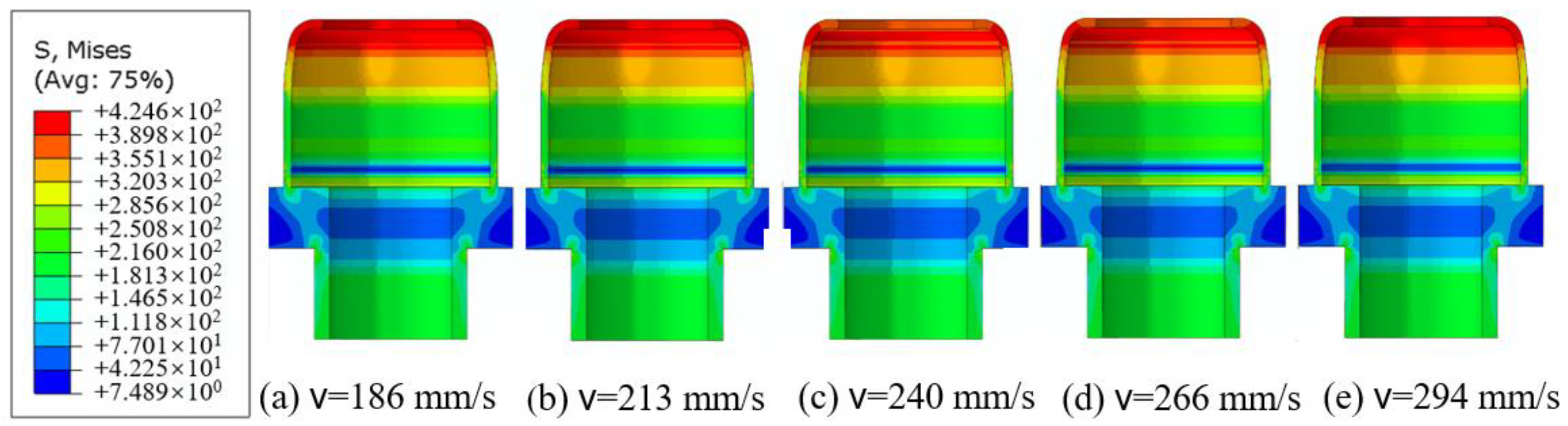
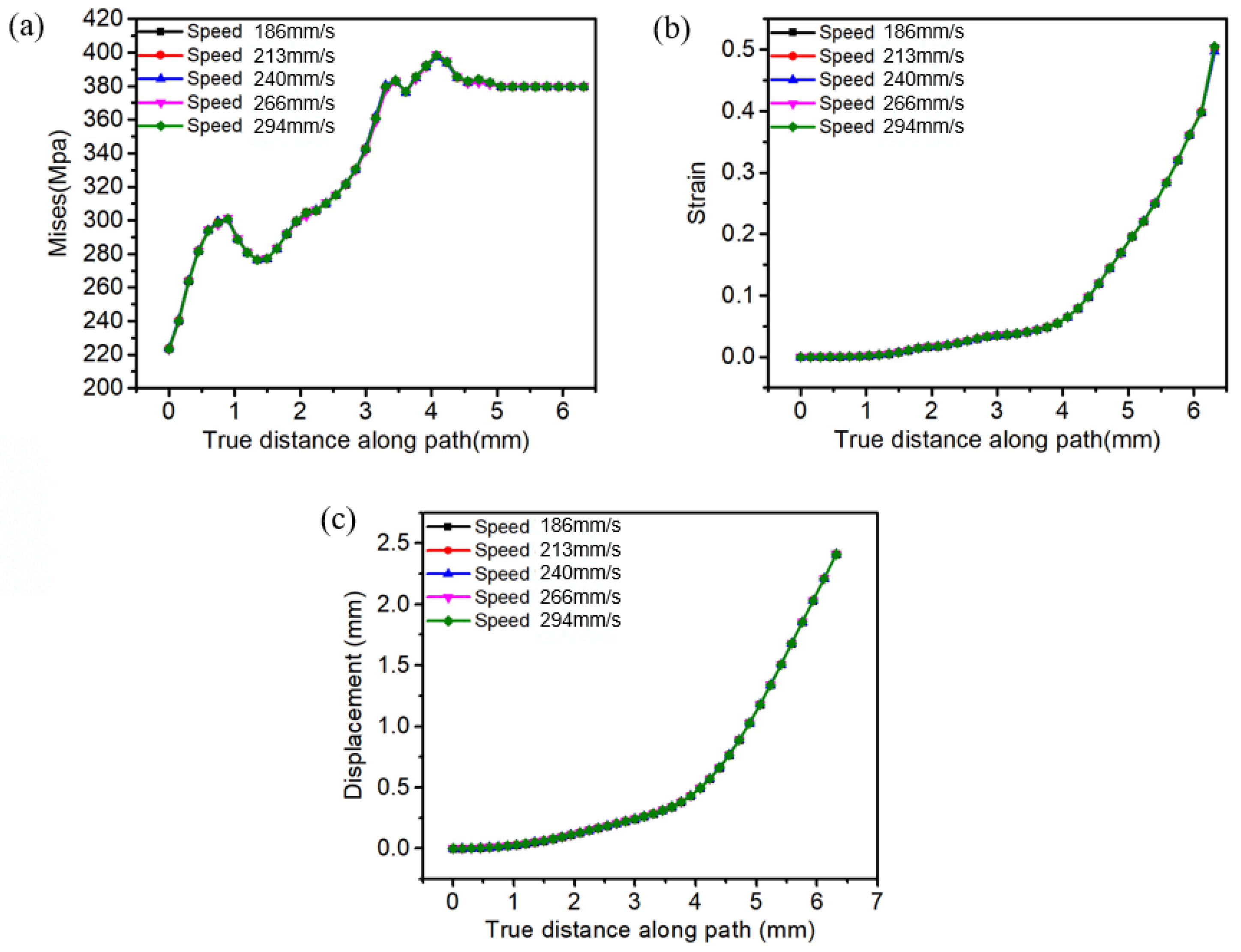
3.3. Effect of the Stamping Velocity on Forming
The stamping press’s stamping velocity is within the range of 186–294 mm/s. With R = 1.8 mm and α = 7°, nosing of the spacing shim with v = 186, 213, 240, 266, and 294 mm/s was simulated. It had no significant effect on the shape of the stamped product, as shown in Figure 8. The dimensions remained unchanged, and so did the stress distributions on the disengagement-free shell.
Figure 8.
Effect of v on stamping.
The equivalent stress, equivalent plastic strain, and displacement at different nodes on the spacing shim path were quantified. Values of equivalent stress at the same node on the path under different values of v varied very slightly, as shown in Figure 9a. Values of equivalent plastic strain and radial displacement at the same node on the path under different values of v were also nearly identical, as shown in Figure 9b,c. Thus, the stamping velocity did not affect the spacing shim’s shape and dimensions.
Figure 9.
Values of equivalent stress (a) equivalent plastic strain and (b) radial displacement (c) at different nodes on the path under different values of v.
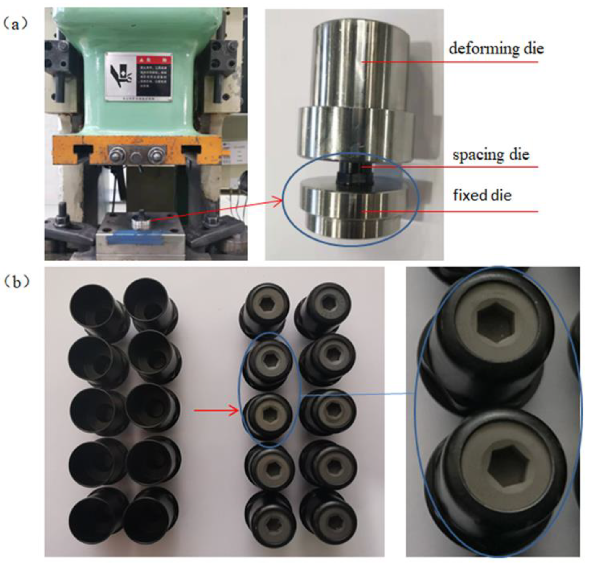
4. Validation of the Nosing Process for the Spacing Shim
Stamping press (SU1-25 from Xieyi Technology Precision Machinery Co., Ltd., Kunshan, China) with the following parameters was employed to validate the applicability of the simulation results. Pressurization capacity = 250 kN, number of strokes = 70–110 s.p.m, forming path = 80 mm, and closing working height = 230 mm. Figure 10a illustrates the test equipment and die for the nosing process of the spacing shims, and Figure 10b shows the product photographs.
Figure 10.
Process validation test: (a) equipment and die; (b) product photographs.
We validated the nosing process for the spacing shims based on different values of three variants, i.e., die’s fillet radius, die’s inclined angle, and stamping velocity. The dimensions of the tested model are identical with those of the simulated model. The nosing dimensions were measured using a digital vernier caliper. The measurement and simulation results are listed in Table 3. As shown in Table 3, the greatest difference between the simulated nosing dimension and measured dimension is 0.02 mm, which indicates that they are very close. As shown in Figure 10b, when the die’s fillet radius (R) = 1.8 mm, its inclined angle and stamping velocity are α = 7° and v = 186 mm/s (the number of stroke = 70 s.p.m), respectively. In addition, visual inspection with a 10× magnifier shows no visible scratches, cracks, or wrinkles in the deformed areas, which proves the validity and feasibility of the nosing process for 2A12 spacing shims that combines the finite element simulation and process test.
Table 3.
Simulated nosing dimension vs. measured nosing dimension.
5. Conclusions
A finite element simulation model was developed to examine R, α, and v, as well as validate the process. The following conclusions were drawn:
(1) The value of R primarily affects the spacing shim’s bending angle: as R increases, the spacing shim’s bending angle decreases, the lengths of straight edges decrease, and the lengths of arc edges increase. Thus, the stamping performance is ideal with R = 1.8 mm.
(2) The nosing die’s inclination angle die primarily affects the spacing shim’s nosing dimension: the nosing dimension increases with the increase in α. With α = 7° (and R = 1.8 mm), the spacing shim’s nosing dimension was within the range of 2.35–2.45 mm, resulting in an ideal stamping performance.
(3) In the range of 186–294 mm/s, v did not affect the formation of the spacing shim.
Author Contributions
Conceptualization, X.W. and Y.C.; methodology, X.W.; software, T.Y.; validation, X.W. and T.Y.; formal analysis, X.W. and Y.C; investigation, Y.C.; resources, X.W. and Y.C; data curation, T.Y.; writing—original draft preparation, X.W.; writing—review and editing, X.W.; visualization, X.W.; supervision, Y.C.; project administration, X.W.; funding acquisition, Y.C. All authors have read and agreed to the published version of the manuscript.
Funding
This project was supported by the National Natural Science Foundation of China (No. 52175379, 51905071), Doctoral Research Startup Fund Program of Liaoning Province (2019-BS-043), and Funding of Ministry of Education Key Laboratory of Precision and Special Processing, Dalian University of Technology (JMTZ201902).
Institutional Review Board Statement
Not applicable.
Informed Consent Statement
Not applicable.
Data Availability Statement
Some or all data and images generated or used during the present work are available from the corresponding authors upon reasonable request.
Conflicts of Interest
The authors declare no conflict of interest.
References
- Deng, Y.; Zhang, X. Development of aluminium and aluminium alloys. Chin. J. Nonferrous Met. 2019, 29, 2115–2141. [Google Scholar]
- Barnes, A.J.; Raman, H.; Lowerson, A.; Edwards, D. Recent Application of Super-formed 5083 Aluminum Alloy in the Aerospace Industry. Mater. Sci. Forum 2013, 735, 361–371. [Google Scholar] [CrossRef]
- Li, B.; Dong, Y.; Wang, H.; Zhou, Y.X.; Gao, C. Research Progress on Corrosion Fatigue of Aerospace Aluminum Alloy. Surf. Technol. 2021, 50, 106–118. [Google Scholar]
- Wang, X.; Niu, G.; Wang, Z. Performance and machining process characteristics of a disengagement-free clamping device. In Proceedings of the 2015 Academic Annual Conference of Shandong Institute of Aeronautics and Astronautics, Qingdao, China, 23–25 May 2015; Beihang University Press: Beijing, China, 2015; pp. 109–112. [Google Scholar]
- Peng, L.; Guo, D.; Wei, Y.; Xu, C.; Duan, B.; Lin, G. Finite element simulation of formation of 2A12 aluminum alloy forgings. Min. Matal. Eng. 2017, 37, 99–104. [Google Scholar]
- Li, Q. Effect factors during aluminium alloy cylinder hot nosing up. Light Alloy Fabri. Technol. 2002, 30, 49–50. [Google Scholar]
- Guo, Y.; Xu, H.; Xue, X.; Wang, D.; Zheng, Y.; Wang, Y.; Huang, T.; Zhao, X.; Liang, C. Power spinning process for thin-walled shell parts of 2 A12 aluminum alloy. Forg. Stamp. Technol. 2021, 46, 143–150. [Google Scholar]
- Jiang, R. Research on Bearing Press Fit and Necking Process Based on Finite Element Simulation; Nanjing University of Aeronautics and Astronautics: Nanjing, China, 2015. [Google Scholar]
- Zhang, H.; Bo, H. Simulation of thermal stamping formation process for carbon fiber composite sheets based on ABAQUS. China Synth. Fiber Ind. 2019, 42, 16. [Google Scholar]
- Zhu, Y.; Zhu, P. Numerical analysis of stamping forming based on ABAQUS. J. Kaifeng Univ. 2015, 29, 83–88. [Google Scholar]
- Wang, Y.; Mao, X.; Qi, Y.; Liu, W.; Sun, H. Stamping forming and finite element simulation of titanium and titanium alloy sheets. Titan. Ind. Prog. 2017, 34, 1–5. [Google Scholar]
- Xing, J. Research on Numerical Simulation and Variable Blank Holder Force Technology of Aluminum Alloy Sheet Stamping; Changchun University of Technology: Changchun, China, 2021. [Google Scholar]
- Ju, M.; Men, X.; Chen, Q.; Xu, X.; Wang, G. Finite element simulation of aluminum alloy internal pressure bending forming with small bending radius based on ABAQUS. Hot work. Technol. 2015, 44, 109–112. [Google Scholar]
- Wang, H. Simulation and Optimization of Stamping Process for Automobile Oil Seal Frameworks; Anhui Engineering University: Wuhu, China, 2015. [Google Scholar]
- Wen, Y. Research and Numerical Simulation of Metal Plastic Forming Based on Ductile Damage Mechanics; Beijing University of Science and Technology: Beijing, China, 2020. [Google Scholar]
- Xie, H. Research on Stamping Process Analysis Theory and Key Technology Based on CAE; Hunan University: Changsha, China, 2003. [Google Scholar]
- Wang, L. Analysis of Material Deformation and Wrinkling Failure in Conventional Metal Spinning Process; Durham University: Durham, UK, 2012. [Google Scholar]
Publisher’s Note: MDPI stays neutral with regard to jurisdictional claims in published maps and institutional affiliations. |
© 2022 by the authors. Licensee MDPI, Basel, Switzerland. This article is an open access article distributed under the terms and conditions of the Creative Commons Attribution (CC BY) license (https://creativecommons.org/licenses/by/4.0/).