Article

Effects of Pulsed Magnetic Field Melt Treatment on Grain Refinement of Al-Si-Mg-Cu-Ni Alloy Direct-Chill Casting Billet

School of Material and Metallurgy, Inner Mongolia University of Science & Technology, Baotou 014010, China
*
Authors to whom correspondence should be addressed.
Metals 2022, 12(7), 1080; https://doi.org/10.3390/met12071080
Submission received: 7 May 2022 / Revised: 12 June 2022 / Accepted: 16 June 2022 / Published: 24 June 2022
(This article belongs to the Special Issue Hot Forming/Processing of Metallic Materials)

Abstract

:
Al-Si-Mg-Cu-Ni alloy is widely used in the manufacture of high-performance car engine parts. Coarse, dendritic α-Al and large primary Si are common in Al-Si-Mg-Cu-Ni alloy DC casting billet, which is harmful to the performance of the final product. In this paper, a pulsed magnetic field melt treatment technique was applied to the melt in the launder of a DC casting platform to modify the α-Al and primary Si in the billet. A transient numerical model was established to analyze the electromagnetic field, flow field and temperature field in the melt during the pulsed magnetic field treatment. The effect of the magnetic energy on the clusters in the melt was analyzed. We found that during the pulsed magnetic field melt treatment, the number of clusters close to the critical size was increased due to the cluster formation work being reduced by the magnetic energy, which facilitated nucleation and refined the solidification structure. Furthermore, the flow velocity increased, and temperature homogenized in the melt during the pulsed magnetic field melt treatment, which benefitted the clusters close to the critical size distributed and maintained in the melt uniformly. The experimental results show that the α-Al and primary Si were small and homogeneous following the pulsed magnetic field melt treatment. The size of α-Al and primary Si was reduced by 25.6–44.4% and 32.2–54.1%, respectively, in the billet center compared to the conventional process.

1. Introduction

Al-Si-Mg-Cu-Ni alloy has been widely used in the automotive industry due to its high strength, good wear resistance and low thermal expansion. This alloy is also used to produce hot forged engine parts [1,2,3]. Direct-chill casting is a typical method of producing Al-Si-Mg-Cu-Ni alloy billets for further processing [4]. The grain size, eutectics, secondary phases and segregation of the billets directly affect the downstream process and performance of the final products [5]. Generally, a finer structure leads to fewer casting defects [6,7], fine machinability [8] and final products with superior mechanical properties [9,10]. To refine the structure of Al-Si-Mg-Cu-Ni alloy DC casting billets, typically, TiB2 [11] or TiC [12] additions are used, and individual elements, such as V [13], Zr and Sr [14] can also be used to achieve grain refinement.
Many researchers have demonstrated that applying external fields is an effective method to improve the metallurgical quality of DC casting billets [15,16,17]. With the advantages of contactless, pollution-free, low-cost and easy operation, the application of electromagnetic fields, such as low-frequency electromagnetic fields and AC and DC combined magnetic fields, in the aluminum alloy DC casting process has become a research hotspot [18,19,20]. Recently, pulsed magnetic field treatment has gained attention due to its advantages of energy conservation and weakening of the skin effect. Research has revealed that pulsed magnetic field casting is a promising process for aluminum alloy DC cast billets grain refinement [21]. However, the details of the grain refinement mechanisms under pulse magnetic fields remain to be elucidated [22]. Some researchers have suggested that the main reason for grain refinement under pulsed magnetic fields is the strong stirring of the melt in the crystallizer due to the Lorentz force, which leads to dendrite fragmentation, and ultimately, those fragments become the nucleus, increasing the nucleation rate [23,24,25]. However, other researchers revealed that the energy of the magnetic field can reduce the energy barrier and improve the nucleation rate [26,27,28].
In this work, pulsed magnetic field melt treatment was applied on the Al-Si-Mg-Cu-Ni alloy DC casting process. A numerical model was established to analyze the interaction with electromagnetic field, flow field and temperature field in the melt during the pulsed magnetic field melt treatment. The experimental and simulation results revealed a mechanism of the effect of magnetic energy on the formation of clusters close to the critical size.

2. Experiment and Numerical Procedure

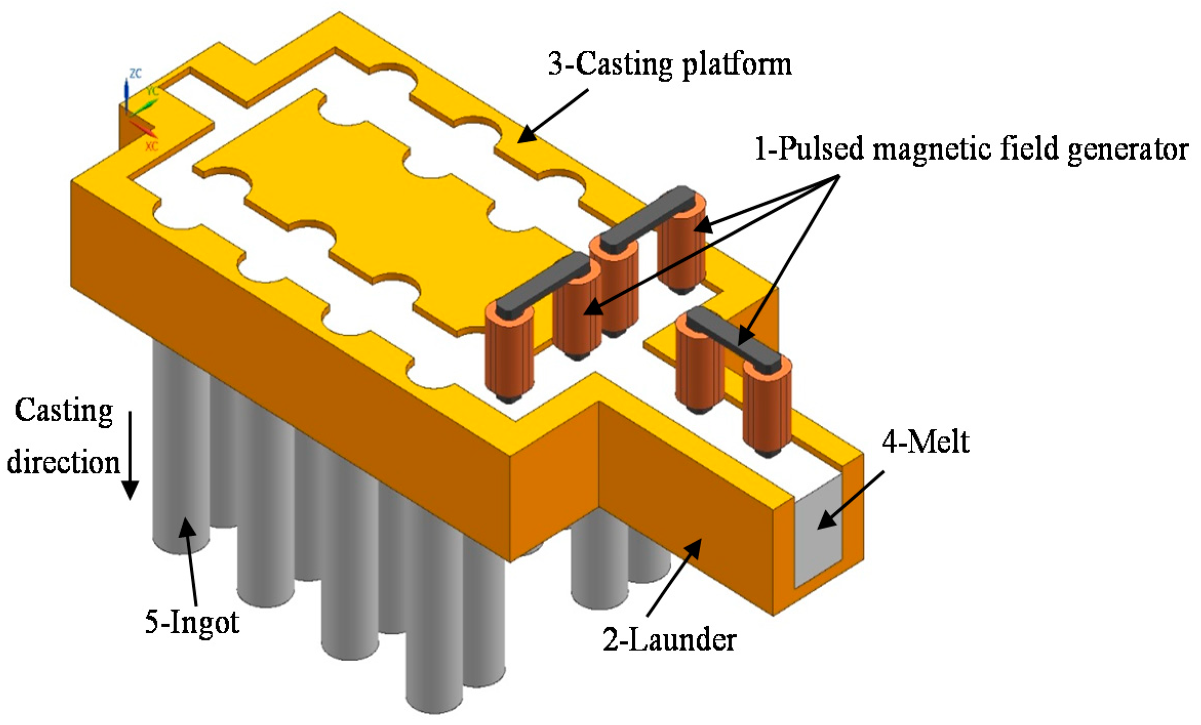
2.1. Pulsed Magnetic Field Melt Treatment Process

Figure 1 illustrates the pulsed magnetic field melt treatment apparatus used in the experiment. In contrast to conventional pulsed magnetic field casting, which is located around the crystallizer [29], the pulsed magnetic field generator was located on the top of the launder of a 3T DC casting platform in this work, as shown in Figure 1. The composition of the alloy was analyzed by a direct-reading spectrometer, with values listed in Table 1. The diameter of the as-cast billet was 120 mm. The casting speed was 0.1 m/s. The cooling water flow rate was 38 m3/h, and the temperature was 294.15 K.
The Al-Si-Mg-Cu-Ni alloy was melted in a furnace. The melt was refined and filtered in the holding furnace at 1023.15 ± 5 K and then poured into the launder and flowed to the crystallizer. The lining of the launder was made of insulation material to minimize heat losses from the launder wall. When the melt flowed into the launder, the apparatus was switched on, and the melt temperature was 993.15 ± 5 K. Details of the current parameters used in the experiment are listed in Table 2. When the length of the billet was 2000 mm, the pulsed magnetic field melt treatment was terminated; then, the conventional process was employed until the length of the billet was 2400 mm, and the casting process was finished.
Several discs with a thickness of about 15 mm were cut from the billet along the cross section with different current parameters. The specimens utilized for structural observation were cut from the center and edge of the disc, as shown in Figure 2. All samples were prepared using the traditional approach for metallographic preparation and then etched with Keller’s solution (5 mL HNO3, 3 mL HCl and 2 mL HF in 190 mL distilled water) for 1 min. Then, the polished samples were characterized using an optical microscope (Axio Observer Z1, Carl Zeiss, Jena, Germany). For quantitative analysis, the size of the α-Al was measured with the linear intercept method, and the size of primary Si was measured with image analysis software. None of the samples received any additional heat treatment before testing.

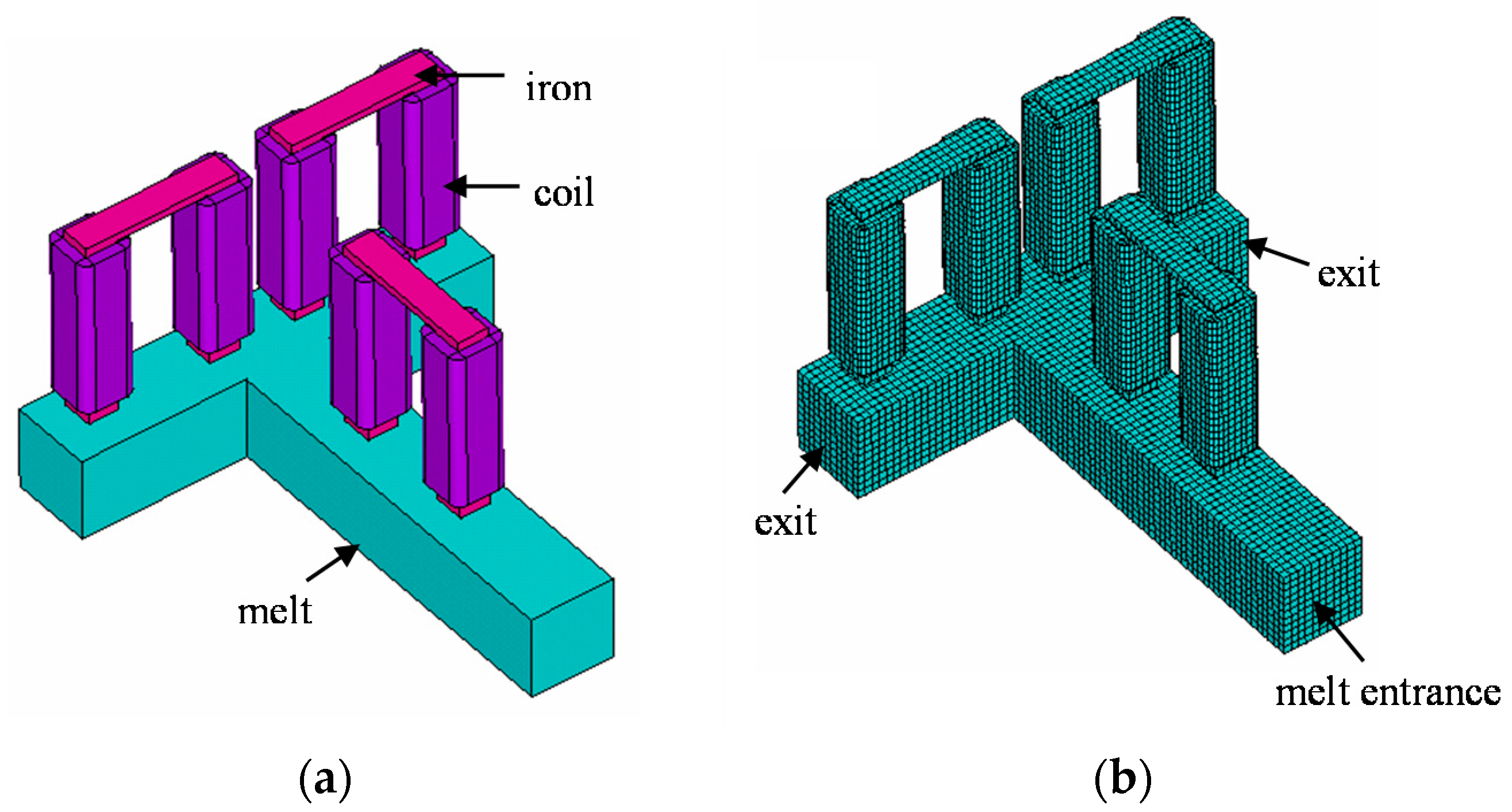
2.2. Numerical Procedure

A numerical model was established to analyze the electromagnetic field, flow field and temperature field in the melt during the pulsed magnetic field treatment. To reduce the computational complexity, the following assumptions were made:
(1) The Joule heat is not considered in this model;
(2) The melt is an incompressible Newtonian fluid and isotropic during the pulsed magnetic field melt treatment process;
(3) The surrounding temperature is 300 K and remains stable.
The three-dimensional physical model and boundaries are given in Figure 3a. The mesh configuration is illustrated in Figure 3b. In this model, the pulsed magnetic field generator consists of two coils and an N-shaped iron core. The coil was loaded with the current parameters listed in Table 2. The velocity inlet boundary was adopted at the melt entrance, and the velocity was set to 0.1 m/s, with a temperature of 993.15 K. The outflow boundary was adopted at the exit regions. The temperature of other walls of the melt was set to 973.15 K.
The pulsed magnetic field melt treatment involves a magnetic field, melt flow field and temperature field, so it must be coupled to analyze the interaction of the multi-physics fields during this process. Thus, the magnetic flux density (B), Lorentz force (F) and electromagnetic energy density were solved with ANSYS software, and the Lorentz force was imported as the source term to calculate the temperature and flow field through with FLUENT software.

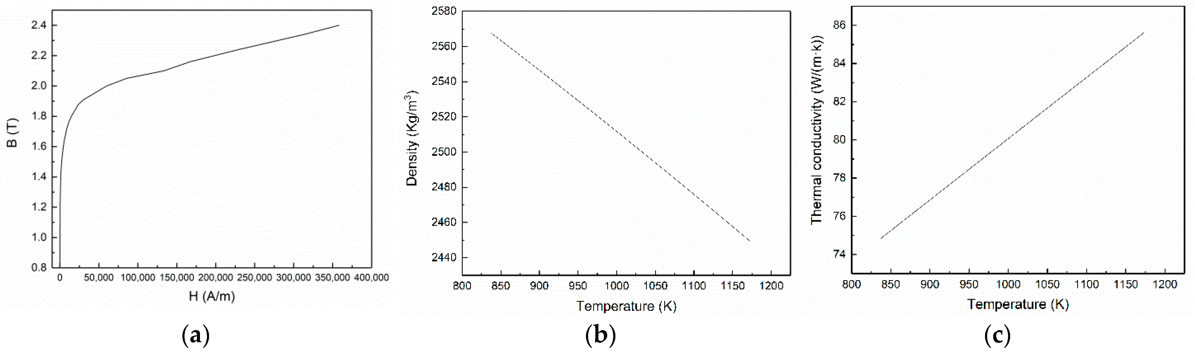
2.2.1. Material Properties

The magnetic properties were obtained from the literature [26,30,31]. The thermophysical properties of the Al-Si-Mg-Cu-Ni alloy used during the calculation procedure were calculated with material performance simulation software. All properties used during the calculation procedure are listed in Table 3.

2.2.2. Governing Equations

The Maxwell equations of the magnetic field in the melt during the pulsed magnetic field melt treatment process can be mathematically expressed as follows:
Ampere s   circuital   law :   × B = μ 0 ( J + ε 0 E t )
Faraday s   law   of   induction :   × E = B t
Gauss s   law :   E = ρ e ε 0
Gauss s   law   for   magnetism :   × B = 0
Electromagnetic   energy   density :   ω t = H B t + E D t
Once the current distribution and the magnetic field density are known, the Lorentz force, F, can be calculated as follows:
F = J × B
where B, E, J, H and D denote the magnetic flux density vector, electric field intensity vector, conduction current density vector, magnetic field density vector and electric flux density vector, respectively.
For the temperature and flow field, the continuity equation is expressed as follows:
( ρ u j ) x j = 0
The energy equation is expressed as follows:
( ρ T ) t + ( ρ U T ) = ( k c p T ) + S t h  
The momentum equation is expressed as follows:
( ρ U ) t + ( ρ U U ) = ( μ U ) P + S m  
where ρ is density; u j denotes the velocity component in the x j direction; S t h is the thermal source and includes the Joule heat and latent heat of solidification; S m is the momentum source and includes thermal buoyancy, Darcy source term and the time-averaged value of electromagnetic force; and μ is effective viscosity.
In this study, the standard k ε model, which is a semiempirical model, was used to model the transport of turbulence kinetic energy ( k ) and its dissipation rate ( ε ):
( ρ k ) t + ( ρ U k ) = [ ( μ l + μ t σ k ) k ] + G k ρ ε + S k ( ρ ε ) t + ( ρ U ε ) = [ ( μ l + μ t σ ε ) ε ] + C 1 ε k G k C 2 ρ ε 2 k + S ε μ t = ρ C μ k 2 ε
where G k represents the generation of turbulence kinetic energy due to the mean velocity gradients, calculated as follows: G k = ρ u u j ¯ u j / x i . C1 and C2 are constants; σ k and σ ε are the turbulent Prandtl numbers for k and ε, respectively; S k and S ε are source terms for k and ε, respectively; and C μ is a function of the turbulent Reynolds number, which is a constant value. All constants used in the model are listed in Table 4.

2.2.3. Model Verification

To verify the accuracy of the simulation model, the magnetic flux density in the air along the centerline was measured. The experimental magnetic flux density versus distance from the iron core surface is shown in Figure 5. The simulated magnetic flux density decreased with the increase in distance, which is in agreement with the experiment results. Thus, it can be concluded that the simulation model is conforms to reality.

3. Results

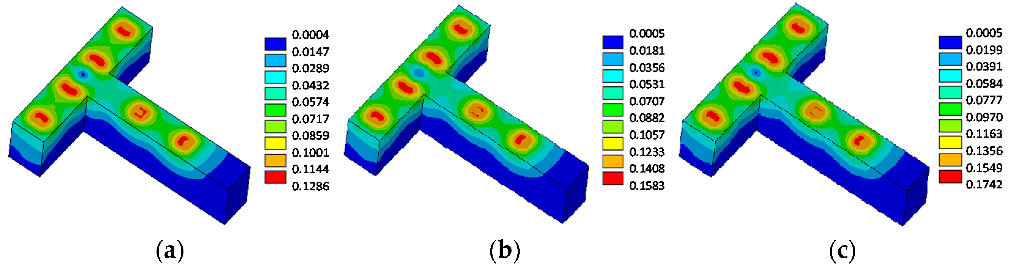
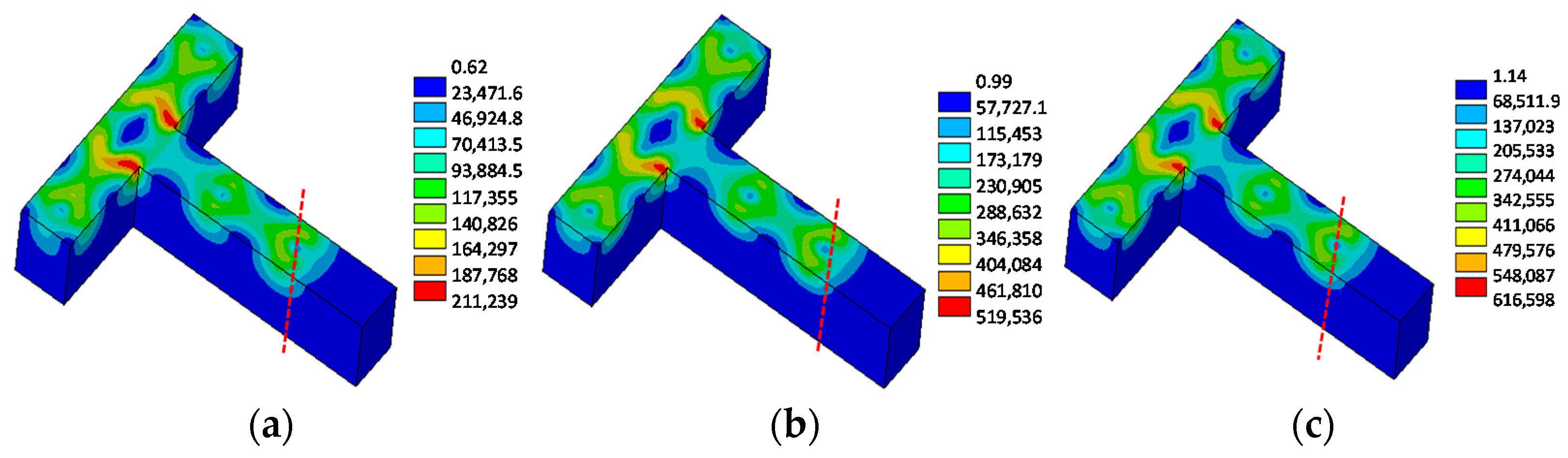
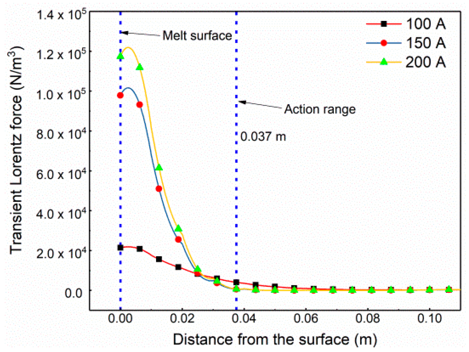
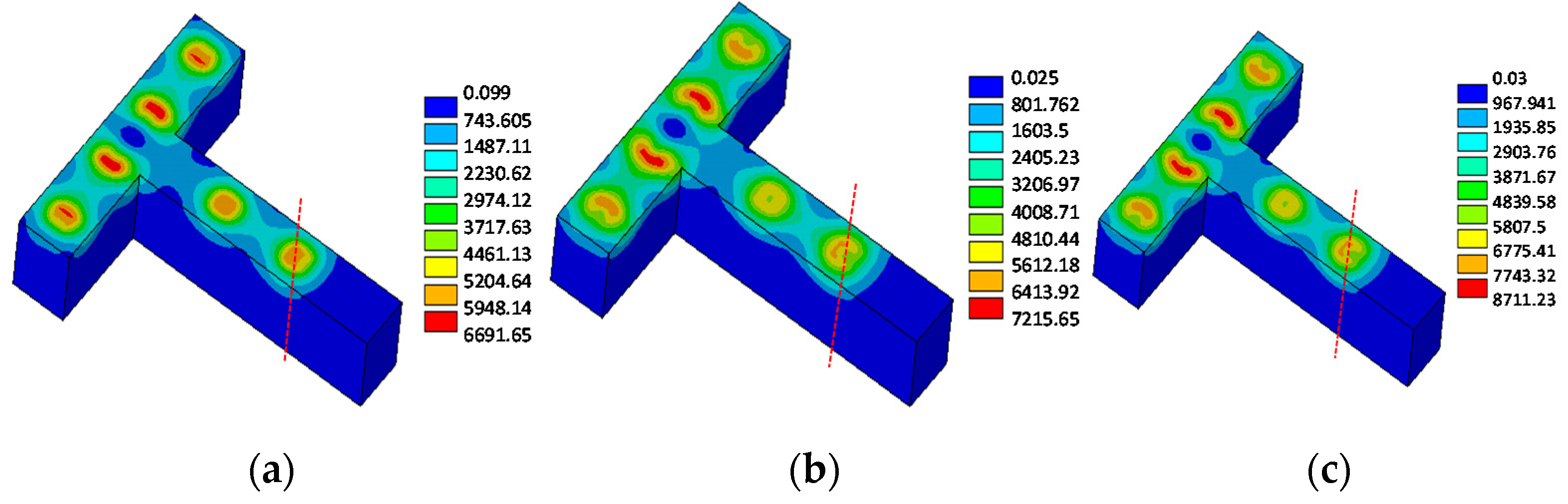
3.1. Distribution of the Magnetic Field in the Melt

The distribution of magnetic flux density under different current parameters is shown in Figure 6. The magnetic flux density decreases from the surface of the melt to the bottom. The maximum magnetic flux density occurs on the surface of the melt, right under the iron core of the pulsed magnetic field generator. Moreover, the maximum magnetic flux density increases from 0.1286 T to 0.158 T and 0.174 T with an increase in the peak value of the excitation current from 100 A to 150 A and 200 A, respectively.
Figure 7 shows the Lorentz force distribution in the melt corresponding to different parameters. Furthermore, the Lorentz force tracked from the path (centerline of iron core extension in the melt), as marked in Figure 7, is shown in Figure 8.
Unlike the maximum magnetic flux density, the transient maximum Lorentz force occurs near the corner of the launder due to the superposition of the electromagnetic field. Figure 8 shows that the transient Lorentz force attenuates exponentially from the top of the melt to the bottom, and the maximum value decreases from 121,910 N/m3 (200 A) to 101,660 N/m3 (150 A) and 21,871 N/m3 (100 A). According to the extension trend of the curves shown in Figure 8, the Lorentz force is mainly located within 0.037 m from the top of the melt under experimental conditions.
The distribution of electromagnetic energy density corresponding to different current parameters is shown in Figure 9. The maximum magnetic energy density is located near the surface, around the iron core. The maximum magnetic energy density tracked from the path, as marked in Figure 9, is shown in Figure 10. The magnetic energy density attenuates exponentially from the top of the melt to the bottom, and the maximum value decreases from 8711.23 J/m3 (200 A) to 7215.68 J/m3 (150 A) and 6691.65 J/m3 (100 A). The infiltration depth of the magnetic energy was 0.03 m.

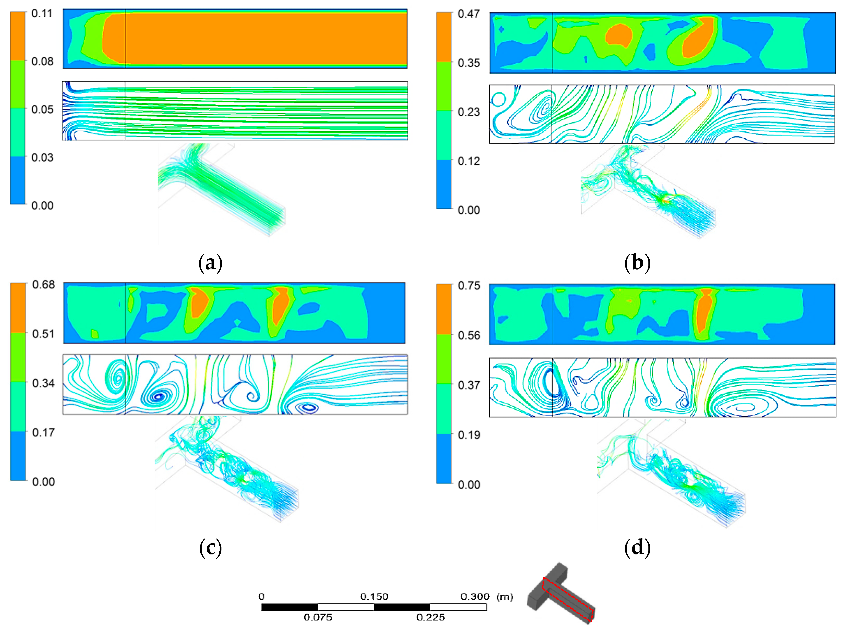
3.2. Distribution of the Flow Field in the Melt

During the pulsed magnetic field melt treatment, the melt in the launder can be affected by the Lorentz force, resulting in a change in the melt flow (including the direction and magnitude of the flow velocity). The flow field can affect the temperature field further, which plays an important role in the evolution of the melt structure, as well as the distribution of alloy elements. Therefore, it is necessary to analyze the changes in the flow field and temperature field in the melt during the pulsed magnetic field melt treatment.
The flow field, including flow velocity and streamlines under different current parameters in the melt, is shown in Figure 11. With an increase in the excitation current, the velocity magnitude increases from 0.11 m/s to 0.75 m/s. The melt flow is also enhanced due to the stronger Lorentz force. As the streamline patterns show, during the pulsed magnetic field melt treatment, there is a circulation in the melt, and the melt is blended in the launder. The circulation also increases with an increase in the excitation current.

3.3. Distribution of the Temperature Field in the Melt

Figure 12 shows the temperature distribution in the melt under different current parameters. The temperature field in the melt declined with the pulsed magnetic field treatment. With the increase in the excitation current, the melt temperature is significantly homogenized, as marked in Figure 12. This phenomenon is induced by forced convection due to the Lorentz forces, which accelerate the heat transfer between the internal and external melt.

3.4. Solidification Structure

Figure 13 and Figure 14 show the microstructures in the center and edge of the Al-Si-Mg-Cu-Ni alloy DC-cast billet, respectively. As shown in Figure 13a and Figure 14a, with the conventional process, the α-Al grain morphology is typical coarse, equiaxed crystal and developed dendritic crystals, whereas the primary Si was large and lamellar. There is a considerable difference in grain size and morphology between the center and edge of the billet. After the pulsed magnetic field melt treatment, the amount of coarse α–Al columnar grain and dendritic crystal progressively decreases, and the primary Si becomes small and uniformly distributed in the α–Al matrix. Meanwhile, the grain morphology is homogeneous in the billet with increased excitation current.
Quantitative analysis of the α–Al grain and primary Si is given in Figure 15. The smallest grain size of α–Al is about 27.9 μm in the center and 27.14 μm at the edge, and the smallest size of primary Si is about 15.9 μm in the center and 13.52 μm at the edge when the melt was treated by the pulsed magnetic field with an excitation current 200 A. Figure 15 also confirms that the size of the α–Al grain and primary Si is significantly decreased and homogenized after the pulsed magnetic field melt treatment.

4. Discussion

The solidification structure size depends on the nucleus number; the more nuclei, the finer the solidification structure. During the pulsed magnetic field melt treatment, the temperature in the interior of the melt is greater than 973.15 K, as shown in Figure 12, and the Al-Si-Mg-Cu-Ni alloy liquid temperature is 837.28 K; thus, the nucleus can hardly be formed in this condition. According to the classical theory of nucleation, there are many clusters with various sizes in the melt, and a cluster near the critical size will become the nucleus during solidification [32]. Due to the structural undulation in the melt, the clusters are more vulnerable to the pulsed magnetic field.
Based on the above analysis, it is difficult to explain grain refinement mechanisms in the pulsed magnetic field melt treatment, so the magnetic energy theory is introduced. In the thermodynamics of the cluster formation, the formation work of a cluster with m atoms in the constant temperature can be expressed as [33]:
G m = ( m 1 ) μ + σ A m
where ∆μ is chemical potential change due to an atom entering the cluster from liquid, determined by temperature; σ is the specific surface free energy; and A m is the surface area of the cluster. During the treatment, the energy of the pulsed magnetic field permeates the melt, and the formation work of a cluster with m atoms is expressed as [27,28]:
G m = ( m 1 ) μ + σ A m χ m 2 w m μ 0 m ν
where χ m is volume susceptibility, μ 0 is the permeability of the vacuum, w m is the magnetic energy density and ν is the volume of the cluster. As Equation (12) shows, the formation work of a cluster with m atoms can be reduced by electromagnetic energy, compared to Equation (11). The formation work of a cluster is decreased significantly as the number of atoms contained in the cluster and magnetic energy density in the melt increases, as shown in Figure 16.
The number of clusters with m atoms in the melt, N m , can be expressed as [33]:
N m = N A · P ( m ) = N A e x p ( G m k B T )
where N A is Avogadro’s number, k B is the Boltzmann constant and G m is the formation work of the cluster with m atoms. As shown in Equation (13), during the pulsed magnetic field melt treatment, the formation work, G m , decreases to G m , which means the number of clusters with m atoms in the melt will increase.
The number of clusters near the critical size in the melt, N n , can be expressed as [34]:
N n = m = 2 n ( A n + N m D n N n )
where A n + is the formation rate, D n is the decomposition rate of the cluster near the critical size and N n is the number of decomposed clusters. As shown in Equation (14), the number of smaller clusters increases in the melt, which facilitates the formation of larger clusters. Finally, the number of clusters near the critical size increases in the melt.
During the solidification stage, the clusters near the critical size form the nucleus; thus, the increase in the clusters near the critical size benefits the increase in the nucleation rate, leading to the refinement of the solidification structure. Thus, the size of the α–Al and primary Si decrease after the pulsed magnetic field melt treatment. Meanwhile, with the increase in excitation current, the magnetic energy in the melt increases, leading to an increase in the number of clusters near the critical size; as a result, the size of the α–Al and primary Si decrease with the increase in the excitation current. Due to the forced convection by the Lorentz force, the melt in the launder are fully mixed, leading to the clusters near the critical size uniformly distributing in the melt, and lower temperature reduces the probability of the cluster decomposition. Thus, the α–Al and primary Si size homogenize in the billet after the pulsed magnetic field melt treatment. Such a pulsed magnetic field melt treatment could be very helpful in solidification structure control of Al-Si-Mg-Cu-Ni alloy DC casting billets.

5. Conclusions

In the present work, a pulsed magnetic field melt treatment was applied in Al-Si-Mg-Cu-Ni alloy DC casting, and a numerical model was established to investigate the magnetic fields, fluid flow and temperature fluid in the melt during the pulsed magnetic field melt treatment. A new mechanism focused on the effect of magnetic energy was presented. The main conclusions are summarized as follows:
1. During the pulsed magnetic field melt treatment, the magnetic energy can decrease the cluster formation work, promote an increase in the clusters near the critical size, forming a large number of the nuclei in the solidification stage, and refine the solidification structure.
2. The flow velocity increases and temperature homogenizes in the melt during the pulsed magnetic field melt treatment, which benefits the clusters near the critical size uniformly distributed and maintained in the melt.
3. The pulsed magnetic field melt treatment can refine the Al-Si-Mg-Cu-Ni alloy DC casting billet solidification structure. Compared to the conventional process, the size of α–Al and primary Si in the center is reduced by 44.4% and 54.1% respectively, when the excitation current is 200A.

Author Contributions

Conceptualization, Y.M. and S.X.; methodology, Y.M. and X.B.; validation, Y.M.; formal analysis, X.B., W.S. and Y.M.; investigation, X.B. and W.S.; resources, Y.M., S.X. and Y.L.; data curation, X.B. and Y.L.; writing—original draft preparation, X.B.; writing—review and editing, X.B. and Y.M.; visualization, W.S. supervision, Y.M.; project administration, Y.M. and S.X.; funding acquisition, Y.M. and S.X. All authors have read and agreed to the published version of the manuscript.

Funding

This research was funded by the Inner Mongolia Natural Science Foundation project, (grant number 2020MS05046) and the Inner Mongolia Science and Technology Planning project (grant number 2021GG0096).

Institutional Review Board Statement

Not applicable.

Informed Consent Statement

Not applicable.

Data Availability Statement

Not applicable.

Acknowledgments

The authors are grateful to BaoTou Aluminum Company Limited for their help in the DC casting work.

Conflicts of Interest

The authors declare no conflict of interest.

References

  1. Pratheesh, K.; Kanjirathinkal, A.; Joseph, M.A.; Ravi, M. Study on the Effects of Squeeze Pressure on Mechanical Properties and Wear Characteristics of near-Eutectic Al–Si–Cu–Mg–Ni Piston Alloy with Variable Cu Content. Inter. Metalcast. 2017, 11, 831–842. [Google Scholar] [CrossRef]
  2. Wang, M.; Pang, J.C.; Zhang, M.X.; Liu, H.Q.; Li, S.X.; Zhang, Z.F. Thermo-mechanical fatigue behavior and life prediction of the Al-Si piston alloy. Mater. Sci. Eng. A 2018, 715, 62–72. [Google Scholar] [CrossRef]
  3. Chankitmunkong, S.; Eskin, D.G.; Limmaneevichitr, C. Structure modification upon ultrasonic processing of an AA4032 piston alloy: Comparison of permanent mold and direct-chill casting. Metall Mater. Trans. A 2020, 51, 818–829. [Google Scholar] [CrossRef] [Green Version]
  4. Subroto, T.; Eskin, D.G.; Beckwith, C.; Skalicky, I.; Roberts, D.; Tzanakis, I.; Pericleous, K. Structure Refinement Upon Ultrasonic Melt Treatment in a DC Casting Launder. JOM 2020, 72, 4071–4081. [Google Scholar] [CrossRef]
  5. Zhang, Y.; Li, R.Q.; Chen, P.H.; Yang, Y.L.; Li, X.Q.; Jiang, R.P. Tuning the microstructure morphology and genetic mechanical properties of 2219 Al alloy with ultrasonic treatment. J. Alloys Compd. 2020, 846, 156251. [Google Scholar] [CrossRef]
  6. Gupta, M.K.; Singla, A.K.; Ji, Q.H.; Liu, Z.Q.; Cai, W.T.; Mia, M.; Khanna, N.; Krolczyk, G.M. Impact of layer rotation on micro-structure, grain size, surface integrity and mechanical behaviour of SLM Al-Si-10Mg alloy. J. Mater. Res. Technol. 2020, 9, 9506–9522. [Google Scholar] [CrossRef]
  7. Zuo, Y.B.; Cui, J.Z.; Zhao, Z.H.; Zhang, H.T.; Qin, K. Effect of low frequency electromagnetic field on casting crack during DC casting superhigh strength aluminum alloy ingots. Mater. Sci. Eng. A 2005, 406, 286–292. [Google Scholar] [CrossRef]
  8. Machado, P.A.B.; Quaresma, J.M.D.V.; Garcia, A.; Santos, C.A.D. Investigation on machinability in turning of as-cast and T6 heat-treated Al-(3, 7, 12%)Si-0.6%Mg alloys. J. Manuf. Process. 2022, 75, 514–526. [Google Scholar] [CrossRef]
  9. Wang, F.Y.; Wang, X.J.; Cui, J.Z. Micro-structure and mechanical properties of 2A97 Al-Li alloy cast by low-frequency electromagnetic casting. Metals 2019, 9, 822. [Google Scholar] [CrossRef] [Green Version]
  10. Wang, F.Y.; Wang, N.; Yu, F.; Wang, X.J.; Cui, J.Z. Study on micro-structure, solid solubility and tensile properties of 5A90 Al–Li alloy cast by low-frequency electromagnetic casting processing. J. Alloy Compd. 2020, 820, 153318. [Google Scholar] [CrossRef]
  11. Li, Y.; Hu, B.; Liu, B.; Nie, A.; Gu, Q.F.; Wang, J.F.; Li, Q. Insight into Si poisoning on grain refinement of Al-Si/Al-5Ti-B system. Acta Mater. 2020, 187, 51–65. [Google Scholar] [CrossRef]
  12. Joseph, O.O.; Afolalu, A.S.; Abioye, A.A.; Agbo, S.E.; Olatunde, S.F.; Omotehinwa, O.S. Effect of TiC addition on the mechanical properties and microstructure of Al-Si alloy. Mater. Today Proc. 2021, 38, 784–788. [Google Scholar] [CrossRef]
  13. Zhao, C.X.; Li, Y.; Xu, J.; Luo, Q.; Jiang, Y.; Xiao, Q.L.; Li, Q. Enhanced grain refinement of Al-Si alloys by novel Al-V-B refiners. J. Mater. Sci. Technol. 2021, 94, 104–112. [Google Scholar] [CrossRef]
  14. Ding, J.H.; Lu, C.; Sun, Y.J.; Cui, C.X.; Zhao, E. Refining and modification effects of (Al, Zr, Si)–Al4Sr on Al–7Si–0.5 Mg alloy. J. Mater. Res. Technol. 2021, 15, 1604–1612. [Google Scholar] [CrossRef]
  15. Subroto, T.; Lebon, G.S.B.; Eskin, D.G.; Skalicky, I.; Roberts, D.; Tzanakis, I.; Pericleous, K. Numerical modelling and experimental validation of the effect of ultrasonic melt treatment in a direct-chill cast AA6008 alloy billet. J. Mater. Res. Technol. 2021, 12, 1582–1596. [Google Scholar] [CrossRef]
  16. Peng, H.; Li, R.Q.; Li, X.Q.; Ding, S.; Chang, M.J.; Liao, L.Q.; Zhang, Y.; Chen, P.H. Effect of Multi-Source Ultrasonic on Segregation of Cu Elements in Large Al–Cu Alloy Cast Ingot. Materials 2019, 12, 2828. [Google Scholar] [CrossRef] [Green Version]
  17. Qi, M.F.; Xu, Y.Z.; Li, J.Y.; Kang, Y.L.; Wulabieke, Z. Microstructure refinement and corrosion resistance improvement mechanisms of a novel Al-Si-Fe-Mg-Cu-Zn alloy prepared by ultrasonic vibration-assisted rheological die-casting process. Corros. Sci. 2021, 180, 109180. [Google Scholar] [CrossRef]
  18. Li, L.; Zhu, Q.F.; Zuo, Y.B.; Cui, J.Z. Study on the transitional structures of 7075 aluminum alloy ingot after switching off a low-frequency electromagnetic field in the horizontal direct chill casting. J. Cryst. Growth 2020, 548, 125827. [Google Scholar] [CrossRef]
  19. Zhao, H.D.; Zhang, Z.F.; Bai, Y.L.; Li, B.; Gao, M.W. Numerical and Experimental Study on the Direct Chill Casting of Large-Scale AA2219 Billets via Annular Coupled Electromagnetic Field. Materials 2022, 15, 1802. [Google Scholar] [CrossRef]
  20. He, C.; Li, S.J.; Li, Y.; Wang, Z.D.; Xu, G.M.; Wu, D. Improvement of Spatial Inhomogeneity of Solute Elements and Mechanical Properties of Twin-Roll Cast Al-Mg-Si Alloy in Presence of Electromagnetic Fields. JOM 2020, 72, 3634–3644. [Google Scholar] [CrossRef]
  21. Jia, Y.H.; Hou, J.; Wang, H.; Le, Q.C.; Lan, Q.; Chen, X.R.; Bao, L. Effects of an oscillation electromagnetic field on grain refinement and Al8Mn5 phase formation during direct-chill casting of AZ31B magnesium alloy. J. Mater. Process. Technol. 2021, 278, 116542. [Google Scholar] [CrossRef]
  22. Jie, J.C.; Yue, S.P.; Liu, J.; StJohn, D.H.; Zhang, Y.B.; Guo, E.Y.; Wang, T.M.; Li, T.J. Revealing the mechanisms for the nucleation and formation of equiaxed grains in commercial purity aluminum by fluid-solid coupling induced by a pulsed magnetic field. Acta Mater. 2021, 208, 116747. [Google Scholar] [CrossRef]
  23. Ren, Z.M.; Lei, Z.S.; Li, C.J.; Xuan, W.D.; Zhong, Y.B.; Li, X. New Study and Development on Electromagnetic Field Technology in Metallurgical Processes. Acta Metall. Sin. 2020, 56, 583–600. Available online: https://www.ams.org.cn/EN/10.11900/0412.1961.2019.00373 (accessed on 6 May 2022).
  24. Wang, F.; Wang, X.; Cui, J. Effect of Low-Frequency Electromagnetic Casting on Micro-Structure and Macro-Segregation of 5A90 Alloy Ingots. Materials 2021, 13, 2720. [Google Scholar] [CrossRef] [PubMed]
  25. Xu, S.; Jia, W.T.; Song, Z.T. Effects of electromagnetic field on physical behaviors during low-frequency electromagnetic casting of Mg alloy AZ31. Mater. Res. Express 2019, 6, 066569. [Google Scholar] [CrossRef]
  26. Bai, Q.W.; Ma, Y.L.; Xing, S.Q.; Bao, X.Y.; Feng, Y.F.; Yu, W.X.; Kang, X.L. Effect of flow, heat transfer and magnetic energy on the grain refinement of 7A04 alloy under electromagnetic pulse. Int. J. Mater. Res. 2017, 108, 1064–1072. [Google Scholar] [CrossRef]
  27. Bai, Q.W.; Ma, Y.L.; Xing, S.Q.; Bao, X.Y.; Feng, Y.F.; Kang, X.L. Nucleation and Grain Refinement of 7A04 Aluminum Alloy Under a Low-Power Electromagnetic Pulse. Mater. Eng. Perform. 2018, 27, 857–863. [Google Scholar] [CrossRef]
  28. Bai, Q.W.; Wang, J.; Xing, S.Q.; Ma, Y.L.; Bao, X.Y. Crystal orientation and crystal structure of paramagnetic α-Al under a pulsed electromagnetic field. Sci. Rep. 2020, 10, 10603. [Google Scholar] [CrossRef]
  29. Luo, Y.J.; Wu, Z.G.; Zhou, L.; He, M.; Zhang, Z.L.; Peng, X.M.; Zhang, Z.F. Effect of Electromagnetic Stirring Position on Uniform Direct Chill Casting of Large-Sized 7005 Alloy Billet. JOM 2020, 72, 4665–4673. [Google Scholar] [CrossRef]
  30. Dong, X.X.; Mi, G.B.; He, L.J.; Li, P.J. 3D simulation of plane induction electromagnetic pump for the supply of liquid Al–Si alloys during casting. J. Mater. Process. Technol. 2013, 213, 1426–1432. [Google Scholar] [CrossRef]
  31. Kaimori, H.; Kameari, A.; Fujiwara, K. FEM computation of magnetic field and iron loss in laminated iron core using homogenization method. IEEE Trans. Magn. 2007, 43, 1405–1408. [Google Scholar] [CrossRef]
  32. Erdemir, D.; Lee, A.Y.; Myerson, A.S. Nucleation of Crystals from Solution: Classical and Two-Step Models. Acc. Chem. Res. 2009, 42, 621–629. [Google Scholar] [CrossRef] [PubMed]
  33. Kelton, K.F.; Greer, A.L. Nucleation in Condensed Matter: Applications in Materials and Biology; Pergamon: Oxford, UK, 2010; pp. 19–52. [Google Scholar]
  34. Christian, J.W. The Theory of Transformations in Metals and Alloys, 3rd ed.; Elsevier Science Ltd.: Oxford, UK, 2002; pp. 85–95. [Google Scholar]
Figure 1. Schematic illustration of the apparatus.
Metals 12 01080 g001
Figure 2. Schematic illustration of discs and samples for microstructural observation. Color lines: the discs location in the billet.
Metals 12 01080 g002
Figure 3. (a) 3D physical model for simulation; (b) mesh model and boundaries.
Metals 12 01080 g003
Figure 4. (a) B-H curve, (b) density and (c) thermal conductivity.
Metals 12 01080 g004
Figure 5. Comparison of the calculated magnetic flux density with the measured values.
Metals 12 01080 g005
Figure 6. Distribution of magnetic flux density: (a) 100 A, (b), 150 A, (c) 200 A (unit: T).
Metals 12 01080 g006
Figure 7. Distribution of Lorentz force: (a) 100 A, (b) 150 A, (c) 200 A (unit: N/m3).
Metals 12 01080 g007
Figure 8. Lorentz force distribution along the tracking path.
Metals 12 01080 g008
Figure 9. Distribution of magnetic energy density: (a) 100 A, (b) 150 A, (c) 200 A (unit: J/m3).
Metals 12 01080 g009
Figure 10. Magnetic energy density along the tracking path.
Metals 12 01080 g010
Figure 11. Flow field in the melt: (a) conventional process; (b) 100 A; (c) 150 A; (d) 200 A (unit: m/s).
Metals 12 01080 g011
Figure 12. Temperature field in the melt: (a) conventional process; (b) 100 A; (c) 150 A; (d) 200 A (unit: K).
Metals 12 01080 g012
Figure 13. Microstructures in the center of the billet: (a) conventional process; (b) 100 A; (c) 150 A; (d) 200 A.
Metals 12 01080 g013
Figure 14. Microstructures on the edge of the billet: (a) conventional process; (b) 100 A; (c) 150 A; (d) 200 A.
Metals 12 01080 g014
Figure 15. Quantitative analysis of the size of (a) α-Al and (b) primary Si.
Metals 12 01080 g015
Figure 16. Effect of magnetic energy on the formation work of the cluster.
Metals 12 01080 g016
Table 1. Chemical composition of the Al-Si-Mg-Cu-Ni alloy [wt%].
SiMgCuNiFeMnZnAl
121.13.02.5≤0.3≤0.2≤0.2Bal.
Table 2. Current parameters used in the experiment.
No.1234
Excitation current/A1001502000
Duty cycle20%20%20%0
Frequency/Hz4040400
Length of the billet/mm0–600600–13001300–20002000–2400
Table 3. Physical properties.
RegionAlloy MeltColiIron Core
Magnetic properties
Relative permeability
Resistivity
B-H curve
Thermophysical properties
Density
Viscosity
Liquidus temperature
Solidus temperature
Thermal conductivity
Specific heat
-
1
2.83 × 10⁻⁷ Ω m
-
-
As shown in Figure 4b
0.0011 kg/m s
837.28 K
782.95 K
As shown in Figure 4c
1101 J/kg k
-
1
1.75 × 10⁻⁸ Ω m
-
-
-
-
-
-
-
-
-
-
-
As shown in Figure 4a
-
-
-
-
-
-
Table 4. Constants is used in the k–ε model.
C1C2 σ k σ ε C μ
1.441.921.01.30.09
Publisher’s Note: MDPI stays neutral with regard to jurisdictional claims in published maps and institutional affiliations.

