Abstract
The present paper illustrates an innovative steel processing route developed by employing hydrogen direct reduced pellets and an open slag bath furnace. The paper illustrates the direct reduction reactor employing hydrogen as reductant on an industrial scale. The solution allows for the production of steel from blast furnace pellets transformed in the direct reduction reactor. The reduced pellets are then melted in open slag bath furnaces, allowing carburization for further refining. The proposed solution is clean for the decarbonization of the steel industry. The kinetic, chemical and thermodynamic issues are detailed with particular attention paid to the slag conditions. The proposed solution is also supported by the economic evaluation compared to traditional routes.
1. Introduction
The direct reduction of iron oxide technologies is considered the best available technique able to greatly reduce the carbon dioxide emissions of steel plants [1]. Mainly, this is obtained by employing natural gas instead of coke or coal [2]. Many approaches have been followed in the development of these solutions; a summary of them is shown in Figure 1.
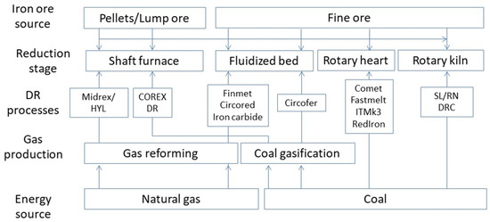
Figure 1.
Main developed direct reduction processes.
Today, direct reduction processes account for over 70% of the total production of direct reduced iron (DRI) and hot briquetted iron (HBI) based on natural gas being used as the main reducing agent. The natural gas is converted to the reducing agents, mainly carbon monoxide and hydrogen, acting as reducing sources of iron oxides. The main industrially diffused technologies are Midrex and HYL-Energiron [3]. The energy consumption of the whole process is essentially dependent on metallurgical, chemical and physical properties of the raw materials [4]. This is amplified in the direct reduction processes because all the transformations act at the solid state. Taking into account the further operations of steel making, ash and sulfur quantities influence the electric arc furnace (EAF) operations [5], so natural gas needs pre-heating in order to be more active for sulfur removal. As a matter of fact, high-quality ores are required for the DRI-EAF steelmaking route [6]. Obviously, the direct reduction reactors are largely located in those regions characterized by large natural gas production or by NG (natural gas) low price availability. A more recently developed solution is the employment of hydrogen instead of natural gas for the reduction of iron ores. The hydrogen direct reduction of iron ores produces mainly iron and water vapor but also CO2 [7,8]. This vapor is optimal for employment in high-temperature electrolyzers for further hydrogen production. Now, more than 90% of hydrogen is produced via fossil sources through various technologies generating carbon dioxide that needs to be treated, captured and stored [9]. In this way, the best means of producing iron with the lowest impact on the environment is the production of hydrogen through electrolysis [10,11]. By employing hydrogen produced via green energy sources as the reducing agent, carbon dioxide emissions can be reduced by 300 kg/t.
The integration of open slag bath furnaces (OSBFs) with direct reduction reactors is an innovative and interesting solution for emission reduction, energy saving and cost reduction. It is believed (and sometimes demonstrated in the literature) that OSBFs are very useful in treating those materials difficult to be melted and processed with an electric arc furnace. So, the OSBF is highly versatile for steel processing in a wide range of potential raw materials to be employed in the direct reduction reactors. In order to precisely describe the OSBFs, it is fundamental to underline those differences with respect to the submerged-arc furnaces. In this case, the furnace electrodes are submerged in the pre-reduced iron and carbon mixture. Electrodes provide the power in the order of 20 MW to the furnace, and the burden resistance allows for the transformation of power into heat in order to melt the material. As a consequence of the difference in the density of the slag and of the metals, the first flows toward the electrodes while the second flows to the bottom of the furnace (Figure 2).
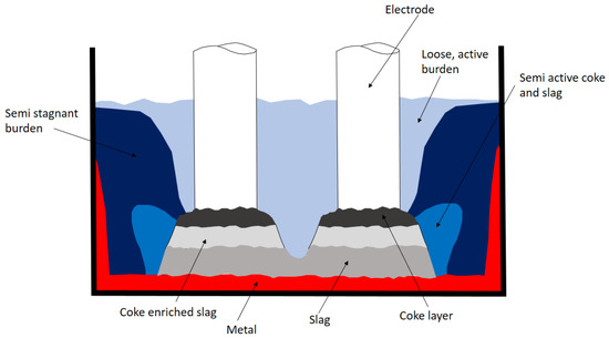
Figure 2.
OSBF (open slag bath furnaces) schematic process behavior.
In the present paper, we present an innovative solution for steelmaking production based on hydrogen-assisted direct reduced iron and subsequent melting and refining in open slag bath furnaces. All the presented results belong to industrial experiences performed on real-scale plants.
2. Experimental Procedure
The employed direct reduction plant was an HYL (TENOVA) reactor (TENOVA Castellanza, Italy) with a production capacity of 900,000 t/year. The employed reducing gas was hydrogen produced via high-temperature water electrolysis; the water vapor from the DR (direct reduction) reactor is employed for electrolysis.
The system is designed in order to reduce blast furnace (BF)-grade pellets, and the composition of the employed raw material is listed in Table 1.

Table 1.
BF-grade pellets employed in the present study.
The employed OSBF furnace was produced by TENOVA Pyromet (Figure 3).
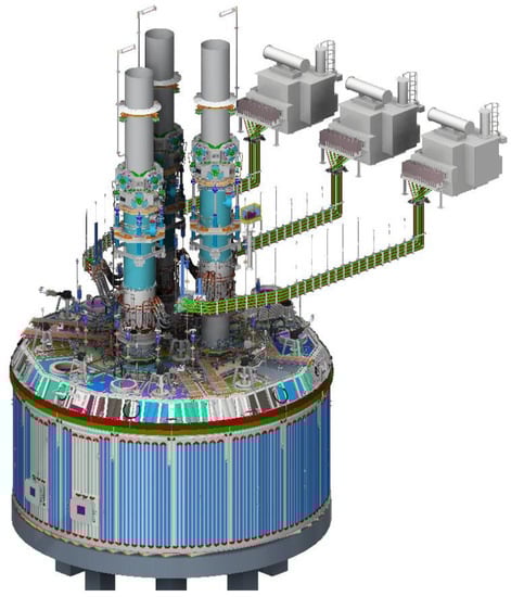
Figure 3.
OSBF layout (direct from TENOVA).
The main characteristics were: internal shell diameter 20 m; +/−110 MVA AC furnace; 75 MW peak power input; 3 single phase transformers; 6 feed bins and 12 feed chutes; MgO conductive lining; 1700 mm Soderberg Electrode (TENOVA, Castellanza, Italy) (Figure 4).
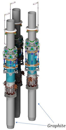
Figure 4.
Soderberg electrodes.
Autofurn™ furnace control system. The gas cleaning is performed through Wet gas scrubbing plant, twin venturi plant design. Chemical energy contained in off-gas is used as an energy source for the DRI reactor.
Figure 5 shows the TENOVA-HYL hydrogen-based direct reduction plant employed in the present study.
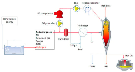
Figure 5.
Schematic of TENOVA HYL-DRI plant.
Due to the high volatility of hydrogen, the pressure employed into the reactor chamber is fundamental for the whole process efficiency. As a matter of fact, the reactor described in Figure 5 has an operating pressure of 6–8 bar, reducing iron ores at a temperature of around 1050 °C. The high pressure of this configuration solves the problem of the gas volatility leading to a remarkable increase in the process efficiency with respect to room pressure configurations. In addition, the described configuration allows for the employment of different reducing gases with different percentages of hydrogen additions. This allows for high flexibility in the use of many energy sources. The iron ore dimensions are in the range 3.2–18 mm. As shown in Figure 5, the plant is equipped with a carbon capture and storage/utilization device in the case of natural gas addition to the hydrogen reducing agent. The schematic of the carbon dioxide removal and utilization is shown in Figure 6.
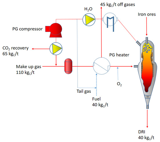
Figure 6.
Carbon balance in the HYL-DRI plant; (PG is the pressurized gas).
In this configuration, carbon dioxide is captured at a rate of 45% and total emissions to the atmosphere reach 30%. The remaining carbon finishes in the direct reduced iron.
Figure 7 shows the comparison of carbon fluxes in the plant schematized in Figure 5 with the equivalent MIDREX plant.
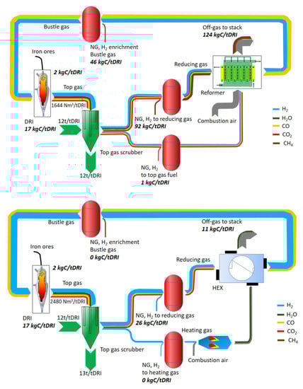
Figure 7.
Schematic of the NG—(up) and H2-based (down) Midrex plants.
3. Results and Discussion
The main unit operations of the process comprise DR-shaft, reformer, top gas scrubber, product gas compressors, and heat exchangers. The reformer allows for the treatment of the natural gas giving the energy required for the syngas production. The top gas scrubber allows one to reduce the water vapor inside the reactor in order to control the temperature during the reducing operations. As a matter of fact, temperature and pressure inside the reactor can be easily controlled. NG can be injected at different process stages: NG as input to the reforming gas, as energy input for heating the reformer or reduction gas heater as well as directly to the bustle gas before entering the shaft furnace. In this configuration, hydrogen is injected into the natural gas before the treatment in the reformer. Once hydrogen is employed instead of natural gas, the reformer is replaced by a gas heater that is a combination of a gas burner, mixer, and heat exchanger model (this is the main solution designed for the Midrex plants). The energy supplied to the heater can also be provided by NG. Both the modelled configurations are based on the same assumptions in order to have comparable results; these are the same solid input material compositions and amounts as well as the same basic assumptions for the DR shaft (e.g., reduction degree, carburization behavior, temperature distribution, and so on), top gas scrubber (temperatures and pressure levels) and gas burner (excess air). In these configurations, about 30% of the NG can be replaced by hydrogen without any process changes. Once hydrogen is added to the natural gas, carbon monoxide decreases in the reducing flow. In fact, if natural gas is employed, carbon monoxide and hydrogen are produced in the reformer; so, as the hydrogen addition is increased, less carbon monoxide is employed as reducing gas. Only a small and constant amount of NG is added for the enrichment of the bustle gas before entering the shaft. In the case of hydrogen directly injected in the reactor, it needs to be previously heated as indicated before. The second schematic belongs to a design for an input of about 95% hydrogen. In this case, natural gas is employed just to retain the desired temperature levels and the carburation of the direct reduced iron. In fact, if only hydrogen is employed, higher recirculating gas flows are necessary to retain the required process temperatures.
Natural gas that is employed during the reforming operations, the enrichment for iron carburization or the gas heating represents the main carbon source in the natural gas-based direct reduction technology. In this configuration, the main carbon output is measured in the reformer off-gas. About 124 kg C/t DRI, which is equivalent to about 453 kgCO2/tDRI, is emitted in this section. In comparison, the carbon output of the DR-H2 process is almost equally distributed between the DRI and stack emissions (released by using the top gas as combustion gas for the heater), representing 17 and 11 kg C/tDRI, respectively. The main carbon source in this case is also NG, which is required for maintaining the carbon content of the DRI (Rechberger et al., 2020).
As mentioned, the TENOVA plant can work with different concentrations of hydrogen in the feeding gas. The plant data as a function of the feeding gas composition are listed in Table 2.
Table 2.
DRI (direct reduced iron) properties and plant characteristics as a function of the gas composition (MTZ is the metallization percentage).
By increasing the hydrogen content in the gas mixture, the total energy required for the process decreases. So, high levels of electricity saving are recorded.
By employing this DRI reactor products as feedstock materials in the BF or in the EAF, a strong reduction in the carbon dioxide emissions can be underlined. The results compared to the traditional BF-BOF route are described in Figure 8.
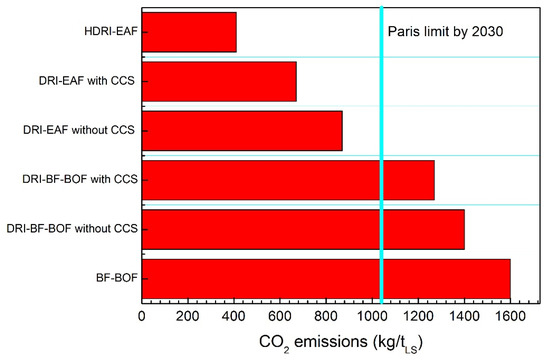
Figure 8.
Carbon dioxide emissions comparison for different routes.
The HDRI (Hydrogen DRI) data refer to a gas mix with 70% H2 and 30% NG. All the data take into account direct and indirect emissions with the assumption of 0.5 kgCO2/kWh. The HDRI-EAF route has a carbon dioxide emissions level of 25% with respect to the traditional BF-BOF route. Hydrogen ironmaking is then considered the future of this very broad field [12].
When talking about the conversion of steel production from the traditional BF-BOF route toward the DRI-based one, it is fundamental to focus on the raw material use, availability and efficiency. First of all, by employing electric arc furnaces, the greenest way is the steel recycling. Irrespective of this, many recent reports show that the concentration of tramp elements in scrap is increasing and incompatible with many high-quality steel grades, so dilution with virgin iron (HBI, DRI, Hot Metal, Pig Iron) is needed. An example is given in Table 3 with special attention on copper concentration.
Table 3.
EAF (electric arc furnace) data with different charge mixes for various liquid steel qualities.
All the data belong to a new-generation electric arc furnace with the following characteristics: type, full-platform AC furnace with EBT and shell diameter of 8900 mm; tap size, 240 t; yearly productivity, 2.2 Mt; transformer rating, 240 MVA; injection system, 17,000 Nm3/f of oxygen.
Now, recent studies show that the forecast for the availability of DR-grade pellets is very flat. The ideal chemical composition for DR-grade pellets has Fe > 67%, SiO2 + Al2O3 + TiO2 < 3% and p < 0.03%. The estimated seaborne DR-grade pellet demand and exports are shown in Figure 9 [13].
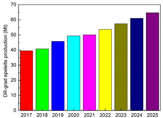
Figure 9.
Direct reduced (DR)-grade pellet production forecast.
So, the availability of DR-grade pellets is limited with respect to global steel production. So, the main obstacles to the direct conversion of steel production are mainly represented by the availability of raw materials that meet the grade requirements. In fact, successful and productive operation of a DR-EAF line requires using high-grade pellets (gangue less than 5%, possibly basic). In addition, some limitations are indicated for fitting the DR-EAF route in integrated plants. By considering the power grid, 250–300 t EAFs (matching the tapping size of large converters to fit the existing CCM) fit transformers of 200–260 MVA, which has massive impacts on the power grid for flicker generation. The integration of BF and EAF is not so simple; the typical cycle times of BF and EAF do not match. EAF typically requires 45–55 min and weekly maintenance stops for refractory repair/relining. With regard to the installation, a 300 t EAF requires a building having at least 26 mt high crane rails and sufficient lifting capacity to lift the complete shell (about 550 t considering complete shell + lifting jig). Finally, by considering the plant logistic, the hot charge of DRI in EAF implies that the DR module is close by, which is typically difficult if the EAF is to be installed in an existing BOF shop to feed the existing downstream equipment.
Taking into account all the described aspects, a good solution appears to be the integration of direct reduction with large smelting furnaces. In this way, BF-grade pellets could be reduced in the DR reactor by overcoming the problem of the availability of high-quality DR-grade pellets. The reduced material is known as DRP (Direct Reduced Pellets). Their refining in the large OSBF allows one to solve the electricity and logistic limitations of the use of EAFs. Given that scientific and technical information is limited, in the following we will give a detailed description of this large smelting furnace.
It is generally observed that the smelting is easier and efficient as the slag liquidus temperature and viscosity are low. These two aspects favor the material separation and flow by lowering the smelting energy requirements. Submerged arc furnaces (SAF) processes are self-regulating, and the material gains heat up to the optimal conditions to flow. All the reducing reactions take place on the formed coke bed. The temperatures strongly vary in different zones, going from 1700 °C at the electrode tip to 500 °C in the upper part of the burden. This is very important because the temperature distribution governs the process efficiency. In this context, the electrode regulation is fundamental for both the furnace productivity and the electrode life in service.
Other factors governing the temperature distributions are the current density, the slag composition and the electrode to metal distance. As a matter of fact, as the basicity of the slag increases, its melting point increases and consequently the reaction zone temperature increases. Both temperature and basicity are fundamental for the evolution of the reduction reaction kinetics. In general, an increase in temperature and basicity leads to reduction increase and to reduction rate decrease [14].
The power input can be controlled by varying the electrode position; this allows one to vary the arc resistance and thereby control the arc current. As the temperature increases, the reduction degree increases if enough coke is provided for the CO formation. The carbon also improves the bath conductivity by increasing the process efficiency.
The main difference between OSBF and SAF is that, in the first one, the electrodes are positioned at the top of the furnace, so they are not submerged in the burden. This arc configuration is known as brush arc or open arc. This arc is produced by varying the position of the electrode tip (Figure 10).
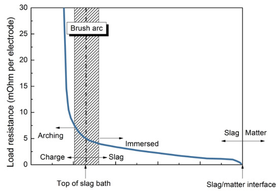
Figure 10.
Operational resistance vs. electrode tip position.
This technology offers some key advantages. The mixture inside the furnace does not influence the electrical current because the electrodes are not submerged. For this reason, fines can be also easily melted. On the contrary, in SAF the burden permeability can be a limit for the process. Given that an open slag bath is created, slag and metal separate very quickly and easily. The feed mixture influences the process chemistry (that can be precisely controlled) and then the process efficiency. Given that the electrodes are not submerged, it is possible to fix the power input; so, the burden properties do not influence the process. Therefore, as a general behavior, precise and improved furnace control is allowed. The reduction kinetics can be easily governed by the DRI percentage injection.
Irrespective of this, by operating with an open arch, some limitations should be underlined. The open bath area results in high heat losses through the roof. This leads to energy dispersion and rapid refractories deterioration that can be reduced by appropriate cooling.
The material is fed to the furnace through the feed pipes. The feed piles that are produced are consumed from the bottom of the furnace as well as from the bottoms of the piles. The combination of large power input and arching on the more refractory slag allows for superheating the iron (Figure 11).
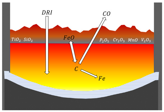
Figure 11.
DRI (direct reduced iron) melting.
As the reaction temperature increases, higher carbon contents are revealed in the iron through dissolution and because of the reduction of the iron melting point. This tends to increase the iron yield, since launder and ladle sculling are minimized. The OSBF also achieves the improvement of sulfur removal thanks to the employed higher slag basicity:
The main reaction taking place in the OSBF is obviously the reduction of iron oxide:
Some iron oxide normally remains unreduced and passes to the slag. In addition, depending on the oxygen potential of the slag, the other reduction reactions involving the additional charge compounds are:
Obviously, the reduction efficiency depends on the oxygen activity and on the furnace temperature.
OSBF is a successful method to produce hot metal from DRI and provides the option to modify slag chemistry, thereby giving greater operational flexibility. OSBF large bath surface area results in a lower slag rise, which reduces the risk of slag foaming. OSBF has a much longer campaign life, reducing the logistic requirements associated with an EAF relining (crane, building, frequent downtime, etc.). Electrical consumption is similar (10% in difference), but the operating costs using Sȍderberg electrodes used on OSBF compared to graphite electrodes is lower, although variable. The OSBF off-gas stream has a high CO content that can be used as fuel for the DRI process gas heater. The BF pellets to be employed in the DRI-OSBF route allows one to reduce the raw material cost by 20% (from 150 to 120 USD/t from DR-grade to BF-grade pellets). In addition, it is demonstrated that the HM produced by the new DRP-OSBF can be merged with the flow coming from the existing BFs. HM analysis and tapping temperature can be adjusted to optimize compatibility and minimize CO2 generation.
The last results belonging to a 2.5 Mt/year DRI reactor integrated with OSBF and BOF show the CO2 emissions reduction indicated in Figure 12.
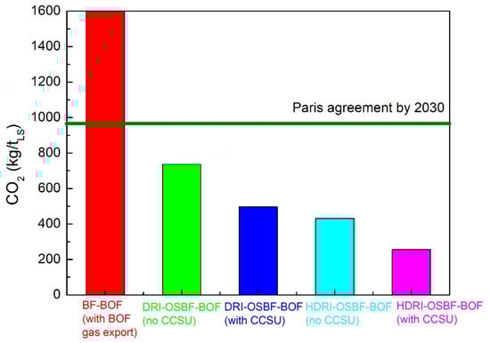
Figure 12.
CO2 emissions for different routes.
Moreover, the costs related to the operations are reduced because of the long-term steady-state operations of OSBF that require refractories replacement each 5–7 years. On the contrary, shell maintenance and repairs in EAFs are required after every 100–120 heats (every 2 weeks). A detailed analysis of the whole process shows the significance of employing the raw materials listed in Table 4.
Table 4.
Raw materials employed in the DRP-OSBF route.
As mentioned above, the temperature control is fundamental. Important energy losses can be recorded once new material is fed into the furnace, the power is needed to melt the solid new material and it cannot be sufficient to retain the optimal temperature in the already meld bath. This severe condition (that can lead to a reduction of 30% in the power efficiency) is known as “overcharged condition”. Obviously, the charge flow must be precisely controlled because, on the contrary, insufficient charge can lead to undesired increases in the temperature with consequent damage in the refractories. This aspect must be carefully considered, and the main factors affecting the furnace reduction reactions are the fed material chemistry, the temperature profile in the furnace and the secondary melting effects. By considering the material chemistry, it is fundamental to continuously monitor the material flow and the composition; both of these factors influence the reaction evolution. The effect of the fresh ores’ flow on the furnace chemistry can lead to the following three different conditions: overcharging accompanied with a drop in the energy provided to the material in the furnace, undercharging accompanied with an increase in the energy and furnace temperature, and balanced charging accompanied with an optimal melting of the material with sufficient power and heating.
The precise correlation between these conditions and the charge feed rate is shown in Figure 13 [15].
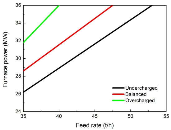
Figure 13.
Relationships between the material feed rate and power for the different conditions.
Essentially, if the power input is constant, once new material is fed into the furnace, the energy provided to the melt decreases. In overcharged conditions, the material tends to accumulate toward the electrodes by producing the bath shrinkage. In these conditions, the temperature decreases and the reduction extent is consequently delayed. The first indicator of this condition is that the percentage of titanium oxide under reduction rapidly decreases. In addition, the equilibrium shifts toward more oxidizing conditions and an increased percentage of iron oxide is revealed in the slag. In addition, very different reacting conditions are experienced in the bath. Carbon accumulates by producing the refractoriness of the bath and the increase in its resistance. So, the slag control is fundamental to the overall process. It is believed that the slag chemistry is governed by the magnesium and calcium oxides as shown in Figure 14.
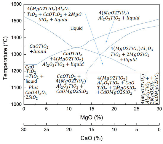
Figure 14.
Effect of CaO and MgO percentages on the liquidus temperature of the slag.
The liquidus temperature is controlled by the CaO percentage irrespective of MgO/SiO2 ratio. By varying the CaO percentage from 20 to 14, the liquidus temperature decreases from 1600 to 1350 °C. The SiO2 percentage governs the spinel transformation and the liquidus temperature (going from 1500 to 1350 °C if the percentage varies from 18 to 24%). Taking into account the combined effect of CaO and MgO, it can be underlined that the slag liquidus temperature varies from 1520 °C at 30% CaO and 0% MgO to the minimum of 1340 °C at 18% CaO and 12% MgO to a new increase at 1505 °C at 0% CaO and 30% MgO.
Many studies indicate that the ratio Ti3+/Ti4+ leads to the variation of the slag temperature. The relationship between the ratio and the TiO2 content is shown in Figure 15.
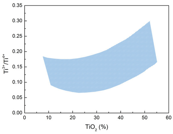
Figure 15.
Effect of TiO2 content on the oxidation state of titanium.
As can be seen from the figure below, the belt variation is due to the basicity of the slag. This is a key factor for the present analyses. Generally, small variation in the basicity of the slag leads to important differences in the liquidus temperature. The summary for selected conditions is described in Figure 16.
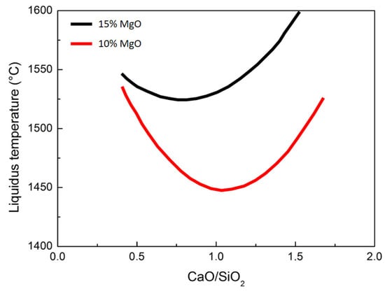
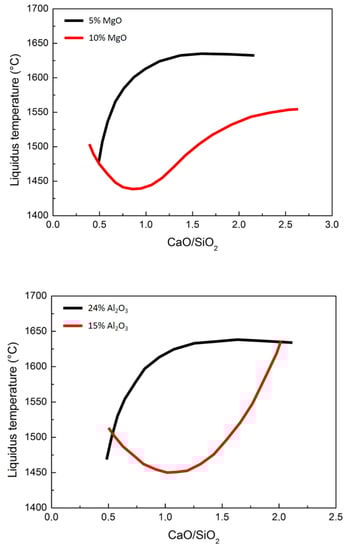
Figure 16.
Effect of slag basicity with diffferent percentages of magnesium oxide (up and central pictures) and alumina (down) on the liquidus temperature.
The most important reduction state variable is the slag basicity. Now, the liquidus temperature is influenced by the contemporary effect of the slag basicity and oxidation state of titanium; it can be concluded that the liquidus temperature in the case of slags with high basicity (CaO/SiO2 = 1.4) decreased with increased reduction (higher Ti3+/Ti4+ ratios). As a consequence, in the case of low-basicity slags (CaO/SiO2 < 0.8), the liquidus temperature decreases and the reduction increases. So, it is possible to modify the liquidus temperature and the Ti3+/Ti4+ ratio by changing the basicity ratio. The furnace chemistry is normally controlled by precisely controlling the material input and the electrode power. During open slag bath furnace operations, product quality and productivity are governed by the tuning of the power/feed ratio. First of all, the raw material composition sensitively influences the overall process. In addition, the feed rate leads to strong variations in the energy consumption. Obviously, in the case of pre-reduced iron ores, the compositional control is fundamental to the optimal evolution of the metal and slag transformations.
As a general trend, the integrated BF-BOF traditional route is not so sensitive to the gangue elements percentage (SiO2, Al2O3 and TiO2) in comparison to the new developed DR-EAF route. During BF transformations, the main percentage of the gangue compounds are transferred to the slag (in the order of 150–300 kg/t) with a total basicity in the order of 1 and with very low iron content (around 1%). In this way, the silicon content in the liquid metal transferred to the BOF falls in the range 0.2–0.7%. As a general trend, as the silicon content in the BF decreases, energy demand decreases and the productivity increases [16]. Much research evidence (the most recent belonging to the blast furnace in Luleå) shows that the minimum limit of SiO2 in BF pellets is around 2%.
Replacing sintered material with pellets has exceptional influences on the energy consumption in the BF. In this configuration, the silica content in the pellets is not so important for the BF route. On the other hand, in the case of the direct reduction route, this content is very important because the process takes place at the solid state. In this case, all the material is sent to the electric furnace, where the slag increases as the gangue results higher.
The silicon in the hot metal and silica and other gangue elements in the DRI affect the amount of slag formers that has to be added to the BOF or the EAF in order to reach the MgO saturation of the slag, and the basicity is typically around 2 or more. The MgO saturation varies with the temperature of the slag and composition as a function of the different compounds, such as FeO, CaO, SiO2, P2O5, Al2O3, TiO2 and VO2. In this way, the process must be controlled through lime addition, so, as the gangue content increases, the lime percentage must be increased [17].
Pellet reduction is strongly influenced by the main properties, such as porosity, particle size and chemical composition, of the phases present in the ore. This must be maximized in order to reach high reducibility, productivity and high metallization degrees of the direct reduced iron.
One of the technical limitations is that, as the metallization degree increases, iron losses increase because of the gangue formation. The metallization obviously depends on the tailing grade of the ores that can fall in the range 10–20%.
Obviously, the slag formation in the EAF is largely influenced by the quality of the scraps employed during the process. This leads to the formation of 70 kg of slag per ton of steel in the case of using 100% of scraps in the EAF. For this reason, scraps must be well treated before entering the EAF in order to reduce this inconvenience.
Given this, a reasonable amount of slag at the end of the DR-EAF process is around 150 kg/t of steel. This is common in the case of low-carbon steel production, where high percentages of FeO can be revealed in the slag.
Again, the high percentage of slag leads to a reduced productivity as well as to increased energy and lime consumption with unbeneficial effects on the process economy. By using DRI from higher grade iron ore feed, slag/steel ratios in the order of 100–120 kg/t are possible for high DRI percentage in the charge (over 80%) with corresponding improvements on the abovementioned factors and the resulting economy.
In the new proposed solution, the DR reactor is a TENOVA HYL-type with a design base of 900,000 t/a of DRP. The OSBF has a shell diameter of 16.500 mm equipped with 1700 mm Soderberg electrodes and a wet gas scrubbing plant. The output material shows the composition listed in Table 5.
Table 5.
Furnace output in the DRP-OSBF route.
A deep analysis was conducted in order to evaluate the economic profitability of the solution. First of all, Table 6 indicates the costs of the Hot DRI or Hot DRP to be employed in the EAF and in the OSBF, respectively.
Table 6.
Direct reduction costs.
First of all, the costs related to the employment of BF pellets are markedly lower with respect to the DRI ones. The costs related to the NG are slightly lower in the case of DRI pellet reduction. A reduction of almost 20% in oxygen consumption is recorded in the case of DRPs. The costs of DRP are 18% lower with respect to DRI ones. In Table 7, the costs belonging to the EAF and OSBF routes are listed.
Table 7.
Costs comparison between DRI-EAF and DRP-OSBF.
First of all, no scraps should be employed in the OSBF route. The electrode consumption and the corresponding cost differences should be underlined.
Actually, the BOF route must be considered, the OSBF metal being very similar to cast iron. The costs relative to the BOF operations for the DRP-OSBF material are listed in Table 8.
Table 8.
Costs for the OSBF-BOF route.
Given the low quality of raw materials, the problem of volatile trace elements is crucial for the environment issues and for the final quality of liquid steel [18]. During the steelmaking processes, many heavy metals and metalloids are emitted into the environment. Due to the high prices and low availability of high-grade ores, industries will go to employ increased quantities of low-grade ores characterized by increased impurity percentages (containing high Pb, Cd, Cr and As). These heavy metals and metalloids are highly toxic, non-degradable and highly dangerous once released into the ground and water sources. On the other hand, the volatile compounds are generally captured and treated in the scrubbers [19].
The volatilization degree as a function of temperature (T) and of the volatilization extent (α) can be expressed as follows:
where k(T) is the volatilization rate constant in the unit s−1, and f(α) is the mechanism function.
The volatilization rate constant k(T) has an Arrhenius-type dependence from the temperature:
where A is the pre-exponential factor (s−1), E is the apparent activation energy (kJ mol−1), and R is the universal gas constant. In non-isothermal conditions, the heating rate can be considered constant:
In this way, the volatilization degree can be expressed by:
By integrating the differential form f(α), the reaction model can be obtained:
Performing transformations and approximations including the Coats–Redfern integration:
The parameters E, A and G(α) (or f(α)) are the kinetic triplet to be determined during the kinetic analysis.
In general, activation energies higher than 40 kJ/mol indicate that the rate-controlling step is the chemical reactions; on the other hand, for energy values lower than 20 kJ/mol, the diffusion is the rate-controlling step.
Many experimental results show that the volatilization of elements such as S, Li, Sn and Pb can be described through a diffusion model. In fact, the activation energy values of Pb and S volatilization are 26.75 and 19.22 kJ/mol, respectively, while Li and Sn show a lower value of 11.65 kJ/mol.
Now, during the overall process, the iron ore particles are cracked through many different mechanisms, such as thermal gradients inside each particle, variations of swelling rates due to the minerology of the ores, local pressures due to volatilization and diffusion processes. This macroscopic thermal cracking takes place with iron oxide reduction and with all the other chemical reactions. So, the volatile element behavior influences the overall process. They can be directly volatilized due to the temperature increase or they can be directly volatilized during the thermal cracking. The rate-controlling step for elemental volatilization could be one of these two mechanisms.
Obviously, each element acts in different way because of its intrinsic nature. As a matter of fact, elements such as As, S, Li, Sn and Pb show continuous volatilization from room temperature up to 1000 °C. As, Pb and S were volatilized in huge quantities after 500 °C; this is in agreement with the clay decomposition and iron oxide transformation of hematite–magnetite–wustite. On the other hand, Li and Sn start to volatilize at lower temperatures, in the range 200–500 °C. Any other increase in temperature does not accelerate volatilization.
4. Conclusions
A new route for steel production has been described in the present paper. An HYL TENOVA direct reduction reactor employing hydrogen as reducing gas was employed for the reduction of blast-furnace-grade pellets. The reduced material was then melted in an open slag bath furnace for further operations. The employment of hydrogen reduced the energy consumption with respect to the natural gas direct reduction route. Through the OSBF route, high carbon liquid metal is obtained with a remarkable difference with respect to the direct reduction of iron ores. Then, the reduced blast furnace pellets can be processed in the BOF by largely reducing the material costs and the energy consumption as well as reducing the overall greenhouse emissions of the steelmaking process. This route allows for steel production at competitive costs compared to the DRI-EAF route with very similar total dangerous emission. It is believed to be an important solution, especially in those situations where the raw material quality can be a problem for the DRI route.
Author Contributions
Conceptualization, P.C., P.S. and P.D.; methodology, P.C, A.P., A.S.; validation, P.C., P.S. and P.D.; formal analysis, P.C., P.S. and P.D.; investigation, A.P., A.S.; resources, P.C., P.S. and P.D.; data curation, P.C., P.S. and P.D.; writing—original draft preparation, P.C.; writing—review and editing, P.C.; visualization, P.C., P.S. and P.D.; supervision, P.C. All authors have read and agreed to the published version of the manuscript.
Funding
This research received no external funding.
Institutional Review Board Statement
Not applicable.
Informed Consent Statement
Not applicable.
Data Availability Statement
Data will be available by contacting the corresponding author.
Conflicts of Interest
The authors declare no conflict of interest.
Abbreviations
| BF | blast furnace |
| BOF | basic oxygen furnace |
| CCM | continuous casting machine |
| CCS | carbon capture and storage |
| DRI | direct reduced iron |
| DRP | direct reduced pellets |
| EBT | eccentric bottom tapping |
| EAF | electric arc furnaces |
| HM | hot metal |
| HDRI | hydrogen DRI |
| HBI | hot briquetted iron |
| MTZ | metallization |
| NG | natural gas |
| OSBF | open slag bath furnace |
| PCI | pulverized coal injection |
| PG | pressurized gas |
| SAF | submerged arc furnace |
References
- Hamadeh, H.; Mirgaux, O.; Patisson, F. Detailed Modeling of the Direct Reduction of Iron Ore in a Shaft Furnace. Metals 2018, 11, 1865. [Google Scholar] [CrossRef] [PubMed] [Green Version]
- Cavaliere, P. Clean Ironmaking and Steelmaking Processes-Efficient Technologies for Greenhouse Emissions Abatement; Springer Nature: Cham, Switzerland, 2019; pp. 1–596. [Google Scholar] [CrossRef]
- Jiang, X.; Wang, L.; Shen, F.M. Shaft furnace direct reduction technology—Mid-rex and Energiron. Adv. Mater. Res. 2013, 805–806, 654–659. [Google Scholar] [CrossRef]
- Schenck, J.; Lüngen, H.B. Review of application of DRI processes in EC countries. Chernye Met. 2017, 2, 25–31. [Google Scholar]
- Khodabandeh, E.; Ghaderi, M.; Afzalabadi, A.; Rouboa, A.; Salarifard, A. Parametric study of heat transfer in an electric arc furnace and cooling system. Appl. Therm. Ener. 2017, 123, 1190–1200. [Google Scholar] [CrossRef]
- Duarte, P.; Martinez, J. Improving performances and decreasing CO2 emissions in blast furnaces installations with high-carbon DRI/HBI. In Proceedings of the AISTech-Iron and Steel Technology Conference Proceedings, Warrendale, PA, USA, 26–27 June 2017; pp. 815–824. [Google Scholar]
- Chevrier, V. Midrex H2 TM: Ultimate low-CO2 ironmaking and its place in the new hydrogen economy. In Proceedings of the AISTech-Iron and Steel Technology Conference; 2018; pp. 725–729. Available online: https://www.midrex.com/tech-article/midrex-h2-ultimate-low-co2-ironmaking-and-its-place-in-the-new-hydrogen-economy/ (accessed on 3 January 2022).
- Zare Ghadi, A.; Valipour, M.S.; Biglari, M. CFD simulation of two-phase gas-particle flow in the Midrex shaft furnace: The effect of twin gas injection system on the performance of the reactor. Int. J. Hydrogen Energy 2017, 42, 103–118. [Google Scholar] [CrossRef]
- Hölling, M.; Weng, M.; Gellert, S. Analysis of sponge iron production with H2. Chernye Met. 2018, 3, 6–11. [Google Scholar]
- Prammer, J. The actual problems of current decarbonization. Chernye Met. 2019, 1, 55–59. [Google Scholar]
- Ranzani da Costa, A.; Wagner, D.; Patisson, F. Modelling a new, low CO2 emissions, hydrogen steelmaking process. J. Clean. Prod. 2013, 46, 27–35. [Google Scholar] [CrossRef] [Green Version]
- Patisson, F.; Mirgaux, O. Hydrogen Ironmaking: How It Works. Metals 2020, 10, 922. [Google Scholar] [CrossRef]
- Poveromo, J. Raw Materials and Iromnaking Global Consulting, «Outlook for DR Grade Pellet Supply for DRI Shaft Furnace Processes. In Proceedings of the STI Webinar, Online, 21 October 2020. [Google Scholar]
- Dishwar, R.K.; Sinah, O.P. Effect of basicity on the activation energy during reduc-tion of highly fluxed iron ore pellets. Fuel 2021, 296, 120640. [Google Scholar] [CrossRef]
- Steinberg, W.S.; Pistorius, P.C. Control of open slag bath furnaces at Highveld Steel and Vanadium Ltd: Development of operator guidance tables. Ironmak Steelmak. 2009, 36, 500–504. [Google Scholar] [CrossRef]
- Cavaliere, P.; Perrone, A. Optimization of blast furnace productivity coupled with CO2 emissions reduction. Steel Res. Int. 2014, 85, 89–98. [Google Scholar] [CrossRef]
- Gyllenram, R.; Arzpeyma, N.; Wei, W.; Jönsson, P.G. Driving investments in ore benefi-ciation and scrap upgrading to meet an increased demand from the direct reduction-EAF route. Min. Econ. 2021. [Google Scholar] [CrossRef]
- Kan, T.; Strezov, V.; Evans, T.; Zhou, X.; Theiss, F.; Frost, R. Volatilisation of trace el-ements during reduction of iron ore by hydrogen: Statistical analysis, kinetic study and environmental assessment. J. Clean. Prod. 2020, 271, 122524. [Google Scholar] [CrossRef]
- Cavaliere, P. Ironmaking and Steelmaking Processes: Greenhouse Emissions, Control, and Reduction; Springer Nature: Cham, Switzerland, 2016; pp. 1–466. [Google Scholar] [CrossRef]
Publisher’s Note: MDPI stays neutral with regard to jurisdictional claims in published maps and institutional affiliations. |
© 2022 by the authors. Licensee MDPI, Basel, Switzerland. This article is an open access article distributed under the terms and conditions of the Creative Commons Attribution (CC BY) license (https://creativecommons.org/licenses/by/4.0/).