Abstract
The stray grain defect is often found at the platform in the process of directional solidification of single crystal blades because local undercooling easily occurs in this area. A variable wall thickness mold based on stereolithography and gelcasting technology was proposed to solve the local undercooling at the platform. The influence of variable wall thickness mold on the temperature field of the platform during directional solidification was studied via simulation. The numerical simulation results show that variable wall thickness can effectively prevent heat dissipation at the platform, thereby reducing the undercooling and avoiding the formation of stray grains. At the same time, the influence of molds assembly angle on the formation of stray grains was analyzed, and the appropriate molds assembly angle is suggested.
1. Introduction
The manufacturing of single crystal (SC) blades of a superalloy is based on directional solidification (DS) technology [1]. During DS, due to the abrupt change of cross-section and rapid cooling of local melt, stray grains mainly appear at the platform [2,3]. Compared with the connection between the platform and the blade body, the temperature at the sharp extremities of the platform is first cooled by the radiation of the cold zone of the furnace, thus forming an undercooled melt. When the undercooling reaches the nucleation undercooling degree of the liquid alloy, it is very likely to form new grains, as shown in Figure 1. The stray grains destroy the integrity of SC, which leads to the decrease of mechanical properties due to the introduction of new grain boundaries [4,5]. Therefore, how to eliminate and control the formation of stray particles at the end of the platform and ensure the integrity of SC has become the focus of SC blade manufacturing.
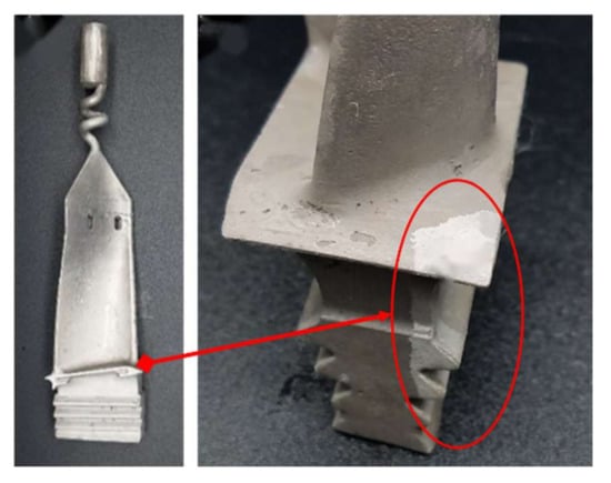
Figure 1.
Stray grains at the platform.
In order to prevent the formation of stray grains, it has been widely studied to eliminate undercooling by improving the local temperature field. Ma et al. installed a graphite block with high thermal conductivity near the platform area to strengthen local heat conduction [6,7,8]. Meyer et al. prevented the early cooling of the alloy melt in this region by arranging insulating materials at the end of the platform [9], and so on. These methods put forward the idea of improving the temperature field during DS by changing the heat dissipation of the mold shell. However, due to the lack of an accurate design, it is difficult to apply it in the actual production on a large scale. Li proposed the integral fabrication technique of ceramic mold (IFTCM) combining stereolithography (SL) with gelcasting to realize the free manufacture of molds, which means that you can adjust the size of any part of the mold according to certain needs [10,11,12]. This breaks the limitation that the traditional investment casting process can only produce a uniform wall thickness mold. The greater the thickness of the mold shell, the slower the heat dissipation during DS. Through the IFTCM, the wall thickness of the mold at different positions of the mold can be flexibly adjusted according to the needs of heat dissipation to realize ideal temperature distribution during DS. In this study, a variable wall thickness mold is proposed to solve the stray grain defects at the platform based on the IFTCM. The influence of wall thickness on the temperature field and on the formation of stray grains at the platform was analyzed during DS. This study is expected to promote the use of an integral ceramic mold technique to provide a better understanding of the influence of mold shell on the temperature field of directional solidification.
2. Materials and Methods
2.1. Ceramic Mold Design
The research object of this paper is mainly the platform, so the structure of other parts of the blade is simplified to reduce an unnecessary amount of calculation. A simplified blade model is designed for numerical simulation, as shown in Figure 2. In this study, the blade is simplified to a model that retains the platform structure, as shown in Figure 2b. The thickness of the platform of the simplified model is 3 mm, and the maximum length is 10 mm. The other dimensions are shown in Figure 2a.
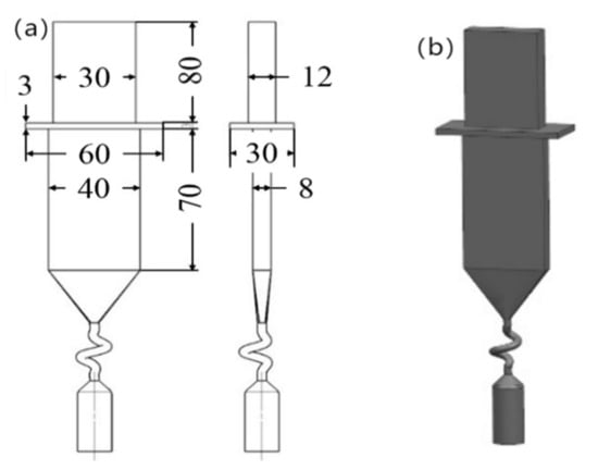
Figure 2.
(a) The design dimensions of the blade(unit:mm); (b) Blade model.
The manufacturing procedures of ceramic mold by SL and gelcasting methods are shown in Figure 3. The SL prototype was manufactured by sps600b (Xi’an Jiaotong University, Xi’an, China) using photosensitive resin (SPR 8981, Zhengbang Technology Co., Ltd., Zhuhai, China). After ball milling for 40 min, alumina-based ceramic slurry with high solid content (60 vol%) was prepared for the gelcasting process. The ceramic slurry with a viscosity lower than 1 pa·s was poured into the SL prototype and polymerized under the action of initiator and catalyst to form a green body. Subsequently, the green ceramic mold was vacuum freeze-dried for 24 h, which helped to reduce shrinkage and avoid drying cracks [13]. Finally, a complete ceramic mold was obtained after pre-sintering and post-treatment [14,15,16].
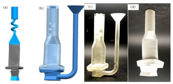
Figure 3.
(a) Blade model; (b) Resin model; (c) Resin mold; (d) Casting mold.
2.2. FEA Model
Based on the designed model, the FEA model is as shown in Figure 4. The sizes of the water-cooling plate and furnace wall are presented Table 1. Through the finite element simulation software PROCAST, the numerical simulation is carried out to investigate the temperature field distribution and microstructure evolution during DS. CMSX-4 nickel superalloy is used as experimental materials for casting, and the main chemical composition is shown in Table 2. Based on the results obtained by Chapman et al. [17], the liquid point (1382 °C) and its thermophysical parameters of the alloy are listed in Table 3. The basic simulation parameters are summarized in Table 4. The three-dimensional model used for simulation, including the furnace wall, water-cooling plate and mold model are shown in Figure 4a. A simulation model and a finite element mesh model were used as the control group as shown in Figure 4b, which have a uniform wall thickness of 7 mm. The variable wall thickness at the platform, namely, 10.5 mm and 14 mm were used as the experimental group; the finite element mesh models of different wall thickness at the platform are as shown in Figure 5. In order to improve the calculation efficiency, non-uniform grid division is adopted. The casting part is divided by the largest 2 mm tetrahedral grid, and the mold shell and water-cooling plate are divided by the larger 8 mm tetrahedral grid.
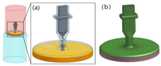
Figure 4.
The casting system: (a) three-dimensional model; (b) grid model.

Table 1.
Dimensions of directional solidification furnace body.
Table 2.
Chemical composition of CMSX-4 Superalloy.
Table 3.
Thermophysical parameters of CMSX-4 Superalloy.
Table 4.
Basic parameter setting of ProCAST numerical simulation.
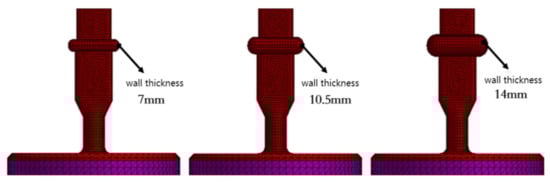
Figure 5.
Mesh model of different wall thickness at the platform.
3. Result and Discussion
3.1. FEA Results
The temperature distribution during DS determines the formation of the local undercooling region at the platform. When the undercooling degree of the local undercooling region reaches the critical nucleation undercooling of the alloy, there is a high probability to produce stray grain defects [20]. The results of the CAFE simulation of grain structure for the control group are as shown in Figure 6a. There are no stray grain defects at the blade body, but some stray grains formed at the platform. Different colors indicate different grains. It can be found that almost all the hybrid crystals are distributed at the edge of the platform.
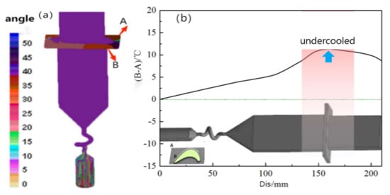
Figure 6.
(a) Simulation results of the CAFE grain structure. (b) Temperature difference of B–A points.
In order to evaluate the effect of local undercooling on the formation of stray grain at the platform, two points with the largest temperature difference at the platform are selected to explain whether the local undercooling leading to the stray grain defect will occur. Point A is located at the tip angle of the platform, and point B is located at the joint position of the blade body and the platform, as shown in Figure 6a.
The temperature difference diagram of point A and point B with time is shown in Figure 6b; the horizontal axis is the displacement of the casting by multiplying the pulling speed and the pulling time, and the vertical axis is the temperature difference between point A and point B. When the value of (B–A) is greater than 0, it indicates that point A solidifies first, and it is easy to form stray grains. When the value of (B–A) is less than 0, point B solidifies first, and it is not easy to form stray grains. The larger the temperature difference between point A and point B, the more prone it is to undercooled nucleation and forming stray grains at point A. It can be clearly seen that the temperature of point A is always lower than the temperature of point B during DS, that is to say, when the temperature of point B drops below the liquidus temperature of 1380 °C, the temperature of point A is lower than the liquidus temperature, thus forming undercooled melt. As the DS proceeds, the undercooling degree of point A gradually increases. Since it takes time for the original grain of blade body to grow laterally along the platform, when the original grain grows laterally to fill the platform, the melt metal at point A has reached the critical undercooling required for nucleation, and the gray strains are formed.
The results of the CAFE simulation of grain structure for the experimental group are as shown in Figure 7, which presents the growth of the grain structure with different wall thickness of 7 mm, 10.5 mm and 14 mm of the mold at the platform when the pulling rate is 3 mm/min. It can be seen that the number of the stray grains at the platform is reduced with the increase of the wall thickness of the mold at the platform, which indicates that increasing the wall thickness of the mold at the platform has an obvious effect on the formation of the stray grains. When the wall thickness of the mold at the platform is 14 mm, the stray grain defects are completely eliminated. This shows that the cooling rate at point A can be reduced by increasing the thickness of the mold at the platform, so that the original grain can extend and grow toward point A in sufficient time before reaching the critical undercooling required for nucleation, and the SC structure can be achieved.
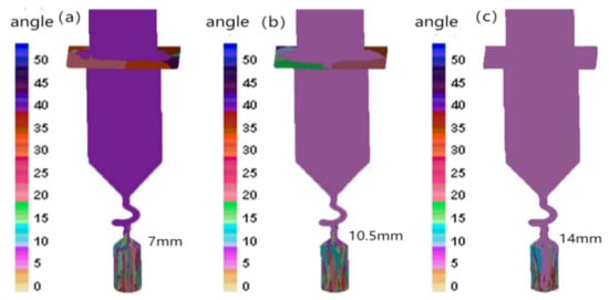
Figure 7.
Simulation results of CAFE grain structure with variable wall thickness: (a) 7 mm; (b) 10.5 mm; (c) 14 mm.
The temperature difference diagram of point A and point B with time is shown in Figure 8. It can be seen that the (B–A) value decreases as the wall thickness of the mold at the platform increases. The (B–A) value is close to 0 when the wall thickness of the mold at the platform is 14 mm; here, it is not easy to form stray grains, so it can be concluded that the gray strain defect at the platform can be eliminated when the wall thickness of the mold is equal to or greater than 14 mm.
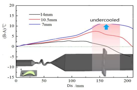
Figure 8.
Temperature difference of B–A points.
3.2. Temperature Field Analysis
In the process of DS, the heat exchange between the furnace and the surface of the ceramic mold is mainly conducted by radiation in a vacuum environment. The heat dissipation from the internal melt metal to the surface of the ceramic mold is mainly through heat conduction. By increasing the wall thickness of the mold at the platform, as shown in Figure 9b, thermal resistance from the inner metal to the surface of the mold can be increased, and the heat dissipation of molten metal at the platform becomes slow. Thus, the undercooling of the melt metal at the platform is greatly reduced, and the formation of stray grains caused by local undercooling is avoided.
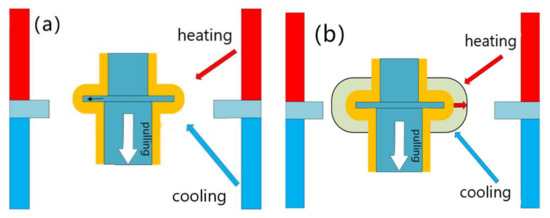
Figure 9.
Schematic diagram of heat exchange between the platform and the furnace: (a) equal wall thickness shell; (b) variable wall thickness mold.
The simulation results of the temperature field with uniform wall thickness at different times and at a pulling rate of 3 mm/min are shown in Figure 10. It can be seen that, when the solidification front enters the blade body at t = 1688 s, the isotherm shows an obvious “concave” shape. As the DS proceeds, the solidification front enters the platform area in a “concave” shape. When t = 1765 s, the temperature of the alloy liquid at the edge of the platform falls below the liquidus earlier, compared with that inside the platform, and undercooled melt is formed first at the edge of the platform. The nucleation of the alloy liquid requires a certain degree of undercooling, which is called critical nucleation undercooling, and the undercooling at this time has not reached the critical undercooling, whereby the alloy liquid at the platform is still in the liquid state. When t = 2113 s, the depression of the isotherm near the platform becomes more obvious, and the undercooling of the alloy liquid at the edge of the platform also continues to increase. When t = 2256 s, the depression of the isotherm near the platform becomes more obvious, and the undercooling degree at the edge of the platform also gradually increases. The undercooling degree of the alloy liquid at the edge of the platform has reached the critical nucleation undercooling, while the original grain has not reached the edge position through lateral growth, so there will be a new grain formed at the platform.
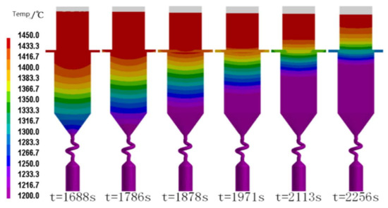
Figure 10.
Temperature field at different times with equal wall thickness shells.
The simulation results of the temperature field with the variable wall thickness mold are shown in Figure 11. This presents the influence of different mold wall thickness of 7 mm, 10. 5 mm and 14 mm at the platform on the temperature field distribution of the casting when the pulling rate is also 3 mm/min. It can be found that, with the increase of the wall thickness of the mold at the platform, the “concave” degree of the isotherm becomes smaller, which can effectively improve the temperature distribution at the platform, as shown in the red dotted squares in Figure 11. When the wall thickness of the mold shell at the platform reaches 14 mm, the solidification front at the platform will tend to be horizontal, as shown in Figure 11c, and the horizontal morphology can effectively avoid the generation of stray grains [21].
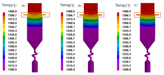
Figure 11.
Temperature field with variable wall thickness mold: (a) wall thickness = 7 mm; (b) wall thickness = 10.5 mm; (c) wall thickness = 14 mm.
3.3. Molds Assembly Angle
In the blade mold assembly structure, the radiation conditions are greatly different at different positions of the mold. The temperature distribution of the melt metal near the heater will be greatly different from that near the center rod due to the different radiation conditions. Different assembly angles will bring different temperature distributions. Therefore, it is necessary to analyze the DS process with different assembly angles to determine the ideal assembly angle. After the reference position is set, a total of 12 positions are rotated at an interval angle of 30° on this reference position, as shown in Figure 12a.
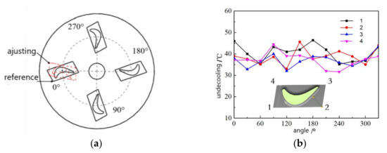
Figure 12.
(a) Schematic diagram of mold assembly; (b) Change of undercooling degree at position 1, 2, 3, 4.
When the pulling rate is 3 mm/min, the undercooling degree of the melt metal at the four sharp corners of the platform are shown in Figure 12b with the increase of the angle. It can be seen that the undercooling degree at point 1, point 2, point 3 and point 4 changes when the angle changes. When the blades rotate to around 270°, the undercooling at the four sharp corners of the platform are all small, which is an ideal assembly angle.
As shown in Figure 13, the mushy zone [22] during DS is analyzed when the angle is 0°, 90°, 180° and 270°. It can be found that the mushy zone near the center is wide, whereas it is narrow near the furnace wall. This is because there are good radiation and heat dissipation conditions near the furnace wall, while the heat dissipation condition near the center is poor [23]. Therefore, the temperature gradient is large near the furnace wall and small near the center. The wider the mushy zone, the larger the temperature gradient. Compared with that of the assembly angle being 0° or 180°, the inclination of the mushy zone is smaller and the mushy zone is narrower when the assembly angle is 90° and 270°, as shown in the red dotted squares in Figure 13. When the assembly angle is around 270°, the mushy zone of the blade body tends to be horizontal, which is conducive to eliminating stray grain defects [24,25,26].
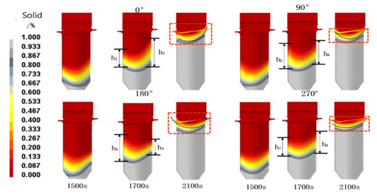
Figure 13.
Mushy zone shape at different assembly angles.
4. Conclusions
- A variable wall thickness mold was manufactured based on SL and gelcasting technology, taking advantage of the flexibility of IFTCM technology. By increasing the wall thickness of the mold at the platform of the blade, the temperature field distribution during DS was improved, and the formation of the gray grains at the platform can be avoided.
- The influence of the variable wall thickness mold on the temperature field of the platform was evaluated. When the wall thickness is varied, the undercooling degree of the alloy melt at the platform can be greatly reduced during DS, thus reducing the possibility of forming stray grains. For the object studied in this paper, when the wall thickness of the mold at the platform is increased to 14 mm, the local undercooling at the platform can be completely solved and the stray grain defects are eliminated. The results of the CAFE simulation also illustrate it.
- The mold assembly angle also has an important influence on the formation of stray grains at the platform. When the blades are placed at different angles, the change of heat dissipation conditions at different parts of the mold will lead to different subcooling degrees at the platform. It is found that there is an ideal mold assembly angle around 270° when the undercooling degree at the platform is relatively small and the solid–liquid interface is relatively straight. It is helpful in eliminating stray grains.
In the DS process of the SC blade, when the pulling rate and other process parameters are determined, the solidification heat dissipation of molten metal is mainly determined by the mold. The variable wall thickness mold can satisfy the needs of the temperature field for SC solidification. Through IFTCM technology combining SL with gelcasting, the shell wall thickness can be adjusted according to the DS demand for SC, providing a new idea for improving the solidification temperature field of SC blades, and good quality of DS can be achieved.
Author Contributions
Conceptualization, Z.L. (Zhefeng Liu) and Z.L. (Zhongliang Lu); methodology, D.L.; software, W.L.; validation, Z.L. (Zhefeng Liu), K.M. and W.L.; investigation, Z.L. (Zhefeng Liu); writing—original draft preparation, Z.L. (Zhefeng Liu).; writing—review and editing, D.L.; funding acquisition, Z.L. (Zhongliang Lu). All authors have read and agreed to the published version of the manuscript.
Funding
This research was supported by the National Science and Technology Major Project (Grant No. J2019-VII-0013-0153), “the Rapid Manufacturing Technology of Complex Hollow Turbine Blade based on Integral Ceramic Mold” of the Insight Action and the National Nature Science Foundation of China (No. 52005392).
Data Availability Statement
Not applicable.
Acknowledgments
This research was supported by the National Science and Technology Major Project (Grant No. J2019-VII-0013-0153), the National Nature Science Foundation of China (No. 52005392) and t. The authors are grateful for the grants.
Conflicts of Interest
The authors declare no conflict of interest.
References
- Fu, H.; Geng, X. High rate directional solidification and its application in single crystal superalloys. Sci. Technol. Adv. Mater. 2001, 2, 197–204. [Google Scholar] [CrossRef]
- Xuan, W.; Li, C.; Zhao, D.; Wang, B.; Li, C.; Ren, Z.; Zhong, Y.; Cao, G. Effect of Primary Dendrite Orientation on Stray Grain Formation in Cross-Section Change Region During the Directional Solidification of Ni-Based Superalloy. Metall. Mater. Trans. B 2016, 48, 394–405. [Google Scholar] [CrossRef]
- Xuan, W.; Liu, H.; Lan, J.; Li, C.; Zhong, Y.; Li, X.; Cao, G.; Ren, Z. Effect of a Transverse Magnetic Field on Stray Grain Formation of Ni-Based Single Crystal Superalloy during Directional Solidification. Metall. Mater. Trans. B 2016, 47, 3231–3236. [Google Scholar] [CrossRef]
- Pollock, T.M.; Tim, S. Nickel-based superalloy for advanced turbine engines: Chemistry, microstructure, and properties. J. Propul. Power 2006, 22, 361. [Google Scholar] [CrossRef]
- Reed, R.C. The Superalloy Fundamental and Applications; Cambridge University Press: Cambridge, UK, 2006; Volume 1. [Google Scholar]
- Ma, D.; Bührig-Polaczek, A. Development of Heat-Conductor Technique for SC Components of Superalloy. Int. J. Cast Met. Res. 2009, 22, 422–429. [Google Scholar] [CrossRef]
- Ma, D.; Polaczek, A.B. Application of Heat-Conductor Technique to Production of SC Turbine Blade. Metall. Mater. Trans. B 2009, 40, 738–748. [Google Scholar] [CrossRef]
- Ma, D.; Bührig-Polaczek, A. Avoiding Grain defect in Single Crystal Components by Application of a Heat Conductor Technique. Int. J. Mater. Res. 2009, 100, 1145–1151. [Google Scholar] [CrossRef]
- Meyerter Vehn, M.; Dedecke, D.; Paul, U.; Sahm, P.R. Undercooling related casting defect in SC turbine blades. Superalloys 1996, 471–479. [Google Scholar]
- Lu, Z.; Zhao, L.; Li, Y.; Wu, H.; Li, D. Thermal Behavior of Integral Al2O3-Based ceramic mold for Fabricating Gas Turbine Blades. Proc. Inst. Mech. Eng. B-J. Eng. 2014, 228, 695–703. [Google Scholar]
- Backman, D.G.; Williams, J.C. Advanced Materials for Aircraft Engine Applications. Science 1992, 255, 1082–1087. [Google Scholar]
- Wu, H.; Li, D.; Tang, Y.; Sun, B.; Cui, F.; Guo, N. Rapid Casting of Hollow Turbine Blades Using Integral Ceramic Moulds. Proc. Inst. Mech. Eng. B-J. Eng. 2009, 223, 695–702. [Google Scholar]
- Tian, G.; Lu, Z.; Miao, K.; Ji, Z.; Zhang, H.; Li, D.; Lloyd, I. Formation Mechanism of Cracks during the Freeze Drying of Gelcast Ceramic Parts. J. Am. Ceram. Soc. 2015, 98, 3338–3345. [Google Scholar] [CrossRef]
- Cai, K.; Guo, D.; Huang, Y.; Yang, J. Solid Freeform Fabrication of Alumina Ceramic Parts Through a Lost Mould Method. J. Eur. Ceram. Soc. 2003, 23, 921–925. [Google Scholar] [CrossRef]
- Wu, H.; Li, D.; Tang, Y.; Sun, B.; Xu, D. Rapid Fabrication of Aluina-Based Ceramic Cores for Gas Turbine Blades by Stereolithography and Gelcasting. J. Mater. Process. Technol. 2009, 209, 5886–5891. [Google Scholar]
- Young, A.C.; Omatete, O.O.; Janney, M.A.; Menchhofer, P.A. Gelcasting of Alumina. J. Am. Ceram. Soc. 1991, 74, 612–618. [Google Scholar] [CrossRef]
- Chapman, L.A. Application of high temperature DSC technique to nickel based superalloys. J. Mater. Sci. 2004, 39, 7229–7236. [Google Scholar] [CrossRef]
- Neuer, G. Spectral and total emissivity measurements of highly emitting materials. Int. J. Thermophys. 1995, 16, 257–265. [Google Scholar] [CrossRef]
- Carter, P.; Cox, D.C.; Gandin, C.A.; Reed, R.C. Process modelling of grain selection during the solidification of single crystal superalloy castings. Mater. Sci. Eng. A 2000, 280, 233–246. [Google Scholar] [CrossRef]
- Ma, D.; Wu, Q.; Bührig-Polaczek, A. Undercoolability of superalloy and solidification defect in single crystal components. Adv. Mater. Res. 2011, 278, 417–422. [Google Scholar] [CrossRef]
- Szeliga, D.; Kubiak, K.; Sieniawski, J. Control of liquidus isotherm shape during solidification of Ni-based superalloy of single crystal platforms. J. Mater. Process. Technol. 2016, 234, 18–26. [Google Scholar] [CrossRef]
- Lu, J.W.; Chen, F. Assessment of mathematical models for the flow in directional solidification. J. Cryst. Growth 1997, 171, 601–613. [Google Scholar] [CrossRef]
- Yu, J.; Xu, Q.Y.; Cui, K.; Liu, B.C.; Kimatsuka, A.; Kuroki, Y.; Hirata, A. Numerical Simulation of Solidification Process on Single Crystal Ni-Based Superalloy Investment Castings. J. Mater. Sci. Technol. 2007, 23, 47–54. [Google Scholar]
- Derby, J.J.; Gasperino, D.; Zhang, N.; Yeckel, A. Modeling the crystal growth of cadmium zinc telluride: Accomplishments and future challenges. Nucl. Radiat. Detect. Mater. MRS Proc. 2009, 1164-L05-02, 45–56. [Google Scholar] [CrossRef]
- Chen, Y.; Billia, B.; Li, D.Z.; Nguyen-Thi, H.; Xiao, N.M.; Bogno, A.-A. Tip-splitting instability and transition to seaweed growth during alloy solidification in anisotropically preferred growth direction. Acta Mater. 2014, 66, 219–231. [Google Scholar]
- Elliott, A.J.; Pollock, T.M.; Tin, S.; King, W.T.; Huang, S.-C.; Gigliotti, M.F.X. Directional solidification of large superalloy castings with radiation and liquid-metal cooling: A comparative assessment. Metall. Mater. Trans. A 2004, 35, 3221–3231. [Google Scholar] [CrossRef]
Publisher’s Note: MDPI stays neutral with regard to jurisdictional claims in published maps and institutional affiliations. |
© 2022 by the authors. Licensee MDPI, Basel, Switzerland. This article is an open access article distributed under the terms and conditions of the Creative Commons Attribution (CC BY) license (https://creativecommons.org/licenses/by/4.0/).