Abstract
Residual stress is a crucial element in determining the integrity of parts and lifetime of additively manufactured structures. In stainless steel and Ti-6Al-4V fabricated joints, residual stress causes cracking and delamination of the brittle intermetallic joint interface. Knowledge of the degree of residual stress at the joint interface is, therefore, important; however, the available information is limited owing to the joint’s brittle nature and its high failure susceptibility. In this study, the residual stress distribution during the deposition of 17-4PH stainless steel on Ti-6Al-4V alloy was predicted using Simufact additive software based on the finite element modeling technique. A sharp stress gradient was revealed at the joint interface, with compressive stress on the Ti-6Al-4V side and tensile stress on the 17-4PH side. This distribution is attributed to the large difference in the coefficients of thermal expansion of the two metals. The 17-4PH side exhibited maximum equivalent stress of 500 MPa, which was twice that of the Ti-6Al-4V side (240 MPa). This showed good correlation with the thermal residual stress calculations of the alloys. The thermal history predicted via simulation at the joint interface was within the temperature range of 368–477 °C and was highly congruent with that obtained in the actual experiment, approximately 300–450 °C. In the actual experiment, joint delamination occurred, ascribable to the residual stress accumulation and multiple additive manufacturing (AM) thermal cycles on the brittle FeTi and Fe2Ti intermetallic joint interface. The build deflected to the side at an angle of 0.708° after the simulation. This study could serve as a valid reference for engineers to understand the residual stress development in 17-4PH and Ti-6Al-4V joints fabricated with AM.
1. Introduction
Owing to its excellent metallurgical and mechanical properties, including high strength-to-weight ratio and excellent heat and corrosion resistances, Ti-6Al-4V has garnered significant interest in structural engineering [1]. It is often used in the nuclear power, chemical, transportation, and aerospace industries [2]. Despite these unique qualities, however, associated high costs and application expenses have limited the widespread use of Ti-6Al-4V [2,3]. It is, therefore, necessary to combine Ti-6Al-4V with a cheaper material with similar properties. 17-4PH stainless steel is a less expensive predominant material widely used in the power, aerospace, and nuclear industries, owing to its high-temperature strength and hardness, excellent corrosion resistance, and high toughness in both weld and base metal. A hybrid structure comprising Ti-6Al-4V and 17-4PH could, therefore, balance the economic and quality aspects for structural applications [3,4,5]. The formation of such an hybrid structure or dissimilar joint involves using (i) a fusion welding process such as laser and electron beam welding and (ii) solid-state welding, including diffusion bonding, friction welding, and explosive welding [6,7,8,9]. However, these techniques are restricted in terms of their capability to fabricate dissimilar parts or structures with complex geometries.
Additive manufacturing (AM) of dissimilar structures has gained considerable attention in aerospace, nuclear, and power generation applications owing to its advantages over conventional joining techniques [10,11]. The process, which involves building up a material layer by layer, has been used in past research efforts to fabricate complex-shaped dissimilar materials with excellent dimensional accuracy, surface quality, and mechanical properties. Examples of dissimilar joints achieved using AM include IN718 and Invar [12,13], Inconel (IN) 625 and 304L stainless steel [14], and pure Fe and Fe-50 at% Al [15]. However, achieving joints comprised of Ti-6Al-4V and stainless steel is difficult owing to several challenges. Among these challenges is the fact that direct fusion joining between Ti-6Al-4V and stainless steel results in crack formation, joint delamination, and failure [16]. This is caused by FeTi and Fe2Ti intermetallic compounds’ formation and the possible accumulation of residual stress [17]. The intermetallic compounds FeTi and Fe2Ti, which have been widely studied in various welding processes, are very brittle and tend to reduce the bond strength, leading to failure and, hence, limiting the performance of hybrid joints [17,18].
Residual stress in AM is similar to welding and occurs because of the rapid heating–cooling thermal cycle. In dissimilar joints, the formation of residual stress strongly depends on the material physical properties, mainly the coefficient of thermal expansion (CTE) [19,20]. The performance and integrity of AM-fabricated structures can significantly deteriorate because of residual stress accumulation [21,22,23]. For dissimilar joints comprised of Ti-6Al-4V and stainless steel, the presence of residual stress causes the brittle intermetallic interface to crack and delaminate. Furthermore, residual stress at the interface of a dissimilar joint can generate angular distortion or loss of geometrical accuracy in one of the deposited alloys [24,25]. For these reasons, much effort has been devoted to understanding, estimating, and controlling residual stress formation in dissimilar metals during AM. Nondestructive (such as X-ray diffraction) and locally destructive (such as hole drilling and nanoindentation) techniques are commonly used to measure residual stress developments in materials [26,27,28]. However, in real-world application, these methods are restricted owing to their limited measurement accuracy, complexity, spatial resolution, time consumption, and suitability for a wide variety of materials [29]. For example, the X-ray diffraction method is limited to fine grain size materials. Further, in the hole drilling method, the material is damaged by measurement, which makes repeating the measurement impossible.
Finite element modeling (FEM) has emerged as a reliable approach for simulating various manufacturing processes, such as AM, welding, pressing and sintering, and forging and can help predict the evolution of residual stress in the early stage [30,31]. Furthermore, FEM simulations help prevent costly trials of failed printed products. Several studies have used modeling tools to investigate residual stress development in dissimilar materials. Venkata et al. [32] used FE analysis to investigate the residual stress in an electron-beam-welded joint between martensitic Grade 91 and austenitic stainless steel. Further, Zhang et al. [33] investigated the residual stress between welded QCr0.8 copper alloy and 304 stainless steel joints using the FE method. Zhou et al. [34] also used FEM to investigate the residual stress distribution in ZrO2/(ZrO2 + Ni) sandwich ceramics fabricated by cold isostatic pressing and sintering. In these studies and others, the FEM results were in fair agreement with experimental data. However, to the best of our knowledge, there are currently no reports on residual stress measurement at the joint interface of titanium alloys and stainless steel investigated by FEM. Specifically in AM, the only research known to us was performed by Sahasrabudhe et al. [16], who calculated the thermal stress in Ti-6Al-4V to be four times that in SS316 during the laser deposition of Ti-6Al-4V on an SS410 substrate, which contributed to cracking and delamination of the joint. The reason for the limited information on the measurement of residual stress in Ti-6Al-4V and stainless steel joints is probably due to the joint’s brittle nature and easy failure susceptibility.
In the current study, the FEM technique was applied to predict the residual stress during the laser deposition of 17-4PH stainless steel on Ti-6Al-4V. A 3D printer was first used to deposit 17-4PH stainless steel on Ti-6Al-4V, and characterization of the delaminated surface was performed using an X-ray diffraction technique. Then, Simufact additive software was used to estimate the residual stress distribution, thermal history, and distortion at the interface of 17-4PH and Ti-6Al-4V after deposition. The simulated thermal histories at the joint interface were then compared to that obtained experimentally and the distortion after simulation measured.
The remainder of this article is organized as follows. Section 2 outlines the experiment conducted, including the equipment and materials used. Section 3 describes the finite element modeling process. Section 4 presents and compares the results obtained in both the experiment and the simulation. Section 5 outlines the conclusions drawn from the study.
2. Experimental
First, direct joining between Ti-6Al-4V and 17-4PH stainless steel was attempted using AM. Ti-6Al-4V plate with thickness 40 mm was obtained from VSMPO and used as the substrate. 17-4PH powders supplied from Carpenters were used in the 3D printer for deposition. The surface of the Ti-6Al-4V bar on which the 17-4PH powder was to be deposited was ground and cleaned ultrasonically with acetone to prevent debris and contamination. A direct-metal tooling 3D printer setup with a laser power of 210 W and 0.3 hatch spacing was used to deposit 17-4PH stainless steel on the thoroughly cleaned surface of a Ti-6V-4Al block. Bidirectional scanning with 90° rotation for every layer was used. A thermocouple was attached to the substrate; this is further elaborated on in later sections. Joint delamination was observed after about seven layers of laser deposition. Figure 1 shows a photographic image of the side view of the deposited joint revealing the delamination.
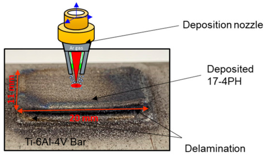
Figure 1.
Photographic image and schematic diagram of the joining process.
3. FEM Modeling
The residual stress of the laser-deposited joint of titanium and stainless steel was simulated using Simufact additive software (MSC Software), which allows the user to predict the stress and breakdown of components during deposition or at the end of production [35]. Simufact additive software has shown success in simulating various manufacturing processes and predicting residual stresses. Jonsson and Krappedal used Simufact additive software to evaluate the residual stresses and distortions in AM components [36]. Furthermore, Bastus utilized Simufact in predicting the residual stress and distortion of 17-4PH stainless steel under different AM process parameters and heat treatment conditions [37].
In the current work, the residual stress and distortion were estimated using the FEM created by the finishing element in Simufact additive software after deposition. As shown in Figure 2a, a fine mesh was utilized within the interface or join area and neighborhood, whereas a coarse mesh was employed for farther regions. These were selected owing to the steep stress and temperature gradients adjacent to the joint interface compared to farther regions. The mechanical and thermal boundary conditions applied in the finite element model were as follows. In the mechanical boundary condition, the bottom of the titanium block was fixed because the block was clamped on the AM machine’s base plate. The thermal boundary condition considered the convection and radiation effect using Equations (1) and (2) on every free surface except the bottom of the Ti-6Al-4V block. The applied convective coefficient was 20.0 W/m2∙K, and the emission coefficient was 0.6. Equations (1) and (2) are expressed as follows:
where , , , .
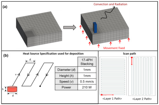
Figure 2.
(a) View of finite element mesh depicting fine mesh in the joint interface and the boundary condition. (b) Heat source specification used for deposition and the scan path.
The heat source specification and scan path used for the simulation is shown in Figure 2b. The laser power, scan speed, and scan path are similar to those used in the actual experiment. Figure 3 and Figure 4 show the thermal–physical-mechanical properties of Ti-6Al-4V and 17-4PH, respectively, used for the simulation.
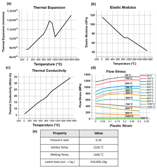
Figure 3.
Properties of Ti-6Al-4V used in the simulation.
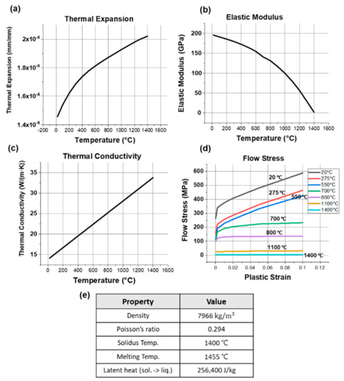
Figure 4.
Properties of 17-4PH used in the simulation.
4. Results and Discussion
The simulated residual stress at the interface and on the faying surfaces of both the Ti-6Al-V and 17-4PH base materials are shown as contour plots in Figure 5. As the primary purpose of this study was to measure the residual stress at the joint, the stresses at farther regions are not discussed. To examine the stress at the inner region of the joint interface, the build was sectioned in half. Figure 5a–c show contour plots of the residual stress distributions along the longitudinal direction of the joint interface, the contact surface of Ti-6Al-4V, and the contact surface of 17-4PH, respectively. There was a steep stress gradient at the inner section of the joint interface; the maximum tensile stress occurred at the interface closer to the 17-4PH stainless steel, whereas compressive stress occurred at the Ti-6Al-V side. The outer edges of the joint interface (indicated by the black arrow in Figure 5a) showed tensile residual stress. These observations were further confirmed by the corresponding stress distributions on the surfaces of the base metals. For instance, large compressive stress appeared at the inner region of the Ti-6Al-4V base metal surface (Figure 5b), whereas tensile stress appeared at the edges. The stress on the faying surface of 17-4PH was mainly tensile in all regions, but the magnitude was higher at the edges than at the inner region. Figure 6 shows the simulated transverse-direction residual stress field for the regions indicated in Figure 5, illustrating that the stress distribution and magnitude of the different regions were similar to those in the longitudinal direction.
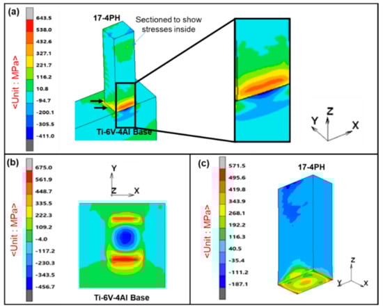
Figure 5.
Residual stress along the longitudinal direction: (a) Stress at interface after section; (b) Stress on Ti-6Al-4V faying surface; (c) Stress on 17-4PH faying surface.
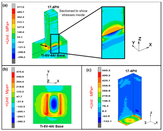
Figure 6.
Residual stress along the transverse direction: (a) Stress at interface after section; (b) Stress on Ti-6Al-4V faying surface; (c) Stress on 17-4PH faying surface.
The high residual stresses at the joint interface compared with the surroundings and farther regions are due to the steep thermal gradient that occurs at the interface. Usually, for joints between two dissimilar metals, a steep thermal gradient occurs at the interface, the magnitude of which depends on the difference in the CTEs of the two base metals [33,38], where a greater CTE difference leads to a steeper thermal gradient and vice versa. The CTEs of Ti-6Al-4V and 17-4PH stainless steel are 8.6 and 11.0 μm·m−1·K−1, respectively [39], which are substantially different. This suggests that the high residual stresses at the interface are attributable to the steep temperature gradient caused by the mismatch in CTE. Another factor that can cause a higher thermal gradient at the joint interface during AM is the coldness of the substrate while depositing the first few layers. The substrate is usually at a lower temperature before deposition begins.
For the selected joint interface, the distribution of tensile residual stress on the 17-4PH side and compressive stress mainly at the inner section of the Ti-6Al-4V side can be explained as follows. During deposition (heating), the significant thermal expansion of 17-4PH was constrained by the cooler Ti-6Al-4V substrate, resulting in tensile stress in Ti-6Al-4V and compressive stress in 17-4PH. Upon cooling, the shrinkage of 17-4PH was restricted by the Ti-6Al-4V substrate. Consequently, Ti-6Al-4V was subjected to compressive stress, whereas 17-4PH underwent tensile stress. 17-4PH and Ti-6Al-4V, therefore, experience cyclic tensile and compressive stresses. A similar case has been reported by Li et al. [40] for the deposition of Cu on SS304L. The maximum tensile stress observed at the joint edges or corners is due to the large mechanical constraint induced by the substrate toward the edge of the joint/build during contraction because the edges cool faster than the inner region. It is common knowledge that, in bulk samples, the cooling rate increases from the center or inner region toward the edges. High tensile stresses at the edges can promote cracking or result in detachment of the substrate component if it exceeds the local ultimate tensile strength (UTS) of the joints during AM [41]. The UTS of both parent metals is greater than the accumulated residual stress. Therefore, no joint delamination, crack formation, or failure should occur at the interface after laser deposition.
However, because mixing of Fe and Ti elements occurs when 17-4PH is deposited on Ti-6Al-4V, the joint interface consists of brittle FeTi and Fe2Ti intermetallic compounds. This intermetallic filled interface has insufficient strength, resulting in cracking and joint delamination boosted by the accumulated residual stresses and subsequent thermal cycles. Such delamination is shown in the deposited 17-4PH on the Ti-6Al-4V substrate in Figure 1. The presence of FeTi and Fe2Ti was revealed by XRD measurement (Figure 7) on the Ti-6Al-4V side of the delaminated joint interface. It was observed that the joint delamination of the Ti-alloy and stainless steel in the current AM joint was absent in similar titanium and steel joints fabricated with welding. For most titanium and stainless steel welded joints, only crack formation is observed at the FeTi and Fe2Ti interface [17,18]. The delamination in the current AM joint can be attributed to the buildup of much higher residual stresses and thermal instability than the traditional joining processes. The intense thermal cycle in AM during subsequent deposition (repeated heating and cooling process) in AM caused the buildup of high stresses and strain. Numerous studies have confirmed the accumulation of high thermal stresses and plastic strains from the intense AM thermal cycles [42,43].
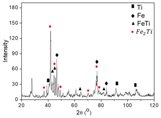
Figure 7.
XRD observation of the delaminated surface of the joint on the Ti-6Al-4V side.
The residual stress in the AM component could also be attributed to the deposition parameters, such as the laser power, laser speed, rotary axes, scan path, and feed rate [44]. The deposition pattern can change the temperature history of the process and, consequently, alter the deposited material’s residual stress [45]. A non-uniform feed, for instance, causes the deposition of extra and undesirable material that damages the part quality through residual stress accumulation [44]. In the scan path, Kruth et al. [46] reported a reduction in residual stress of printed steel components when the scanning path in every single island was inclined 45° to the x-axis.
Figure 8 shows the equivalent residual stress at the joint interface and the corresponding plot, where the short dashed arrow at each observed region indicates the path for the plot. A maximum equivalent stress of ~500 MPa was observed at the joint interface closer to the 17-4PH stainless steel, whereas an average stress of ~240 MPa was observed on the Ti-6Al-4V side. Considering the uncertainty that usually occurs during residual stress simulations, the simulated results need to be validated through comparison. First, it was difficult to experimentally measure the fabricated joint interface’s residual stress because the deposited joint was delaminated after deposition of a few layers. Therefore, a comparison of the accumulated heat during 17-4PH deposition at the joint interface of the simulation and actual AM experiment was made because the laser deposition parameters (scan path, laser speed, scan speed) used in the experiment and simulation are the same. This can also serve as a way of validating the simulation with real experiments, because heat distribution or the temperature history in components plays a role in the residual stress distributions [47].
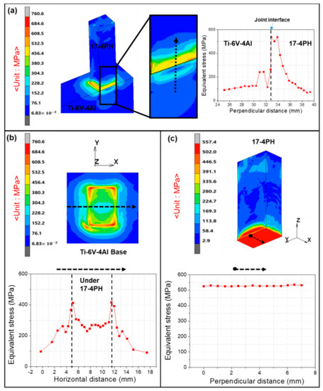
Figure 8.
Equivalent residual stress at (a) interface after section, (b) Ti-6Al-4V faying surface, (c) 17-4PH faying surface. The corresponding graphical plot was taken along the short dashed arrow path.
In the experiment and simulation, before 17-4PH deposition, a thermocouple was attached to the substrate (Ti-6Al-4V) to measure the heat distribution at the joint. The attachment of the thermocouple to the substrate is schematically shown in Figure 9. The figure shows the temperature history for the simulation and experiment, respectively. The simulation showed maximum, minimum, and average temperatures of 477, 260, and 368 °C, respectively. In the experimental result, maximum, minimum, and average temperatures of 450, 150, and 300 °C were recorded. It could be seen that the temperature recordings in the actual experiment deviated marginally from the simulation. These temperatures were lower than that of the simulation and could be attributed to the thermocouple position on Ti-6Al-4V. The thermocouple attachment was far from the joint interface and could not provide accurate measurements for the joint interface.
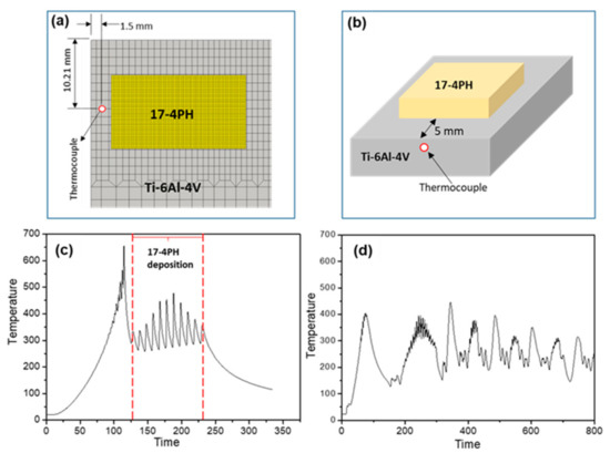
Figure 9.
Position of thermocouple in the (a) simulation and (b) actual experiment. (c) Thermal history in the simulation, and (d) thermal history in the experiment.
The simulated result was further validated by comparing the equivalent stress values with thermal residual stress calculations based on the Young’s moduli and CTEs of Ti-6Al-4V and 17-4PH. We first define the thermal stress as
where E is the Young’s modulus, α is the CTE, and dT is the temperature gradient. The parameters for Ti-6Al-4V and 17-4PH are denoted by the subscripts Ti64 and 17-4ph, respectively. The temperature gradient is assumed to be constant on both sides of the joints, and hence dTTi64 = dT17-4ph = dT. Usually, ETi64 = 110 GPa and E17-4ph = 190 GPa, even though parts fabricated with AM can be stronger than those fabricated by other techniques owing to the finer microstructures arising from rapid cooling. For the CTEs, αTi64 = 8.6 × 10⁻⁶ m⋅m−1⋅°C−1 and α17-4ph = 11.0 × 10⁻⁶ m·m−1·°C−1. Substituting these into Equation (3) yields σTi64 = 9.5 × 10⁵ dT and σ17-4ph = 20.9 × 10⁵ dT (the resultant σ values are in Pa). From the calculations, assuming no other phases are formed, the thermal stress that develops in 17-4PH (σ17-4ph = 20.9 × 10⁵ dT) is approximately twice the stress that develops in Ti-6Al-4V (σTi64 = 9.5 × 10⁵ dT). This result is well matched with the simulations, as the equivalent stress on the 17-4PH surface (~506 MPa) was approximately two times that on the Ti-6Al-4V surface (240 MPa).
σ = E * α * dT
From the two comparisons made above, it is clear that our simulation could serve as a valid reference for designers and engineers to understand residual stress development during the AM of 17-4PH and Ti-6Al-4V. Figure 10 shows the deformation angle model after the simulation, which shows that, after the deposition of 17-4PH, the build deflects to the side at a deformation angle of 0.708°. This deflection was a result of the displacement caused by residual stress accumulation. The deformation angle or degree of inclination was calculated using the displacement values in the formula indicated in Figure 8.
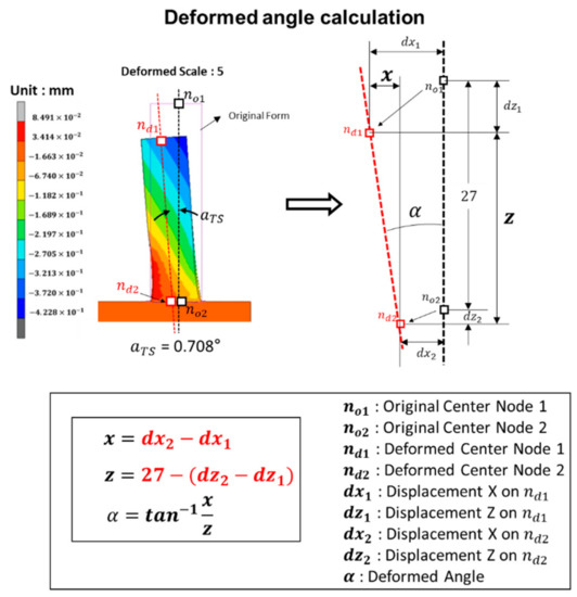
Figure 10.
Contour plot of the displacement and deformation angle calculation.
5. Conclusions
This paper reported the use of Simufact additive software based on the FEM technique to predict the residual stress at the interface of a joint composed of 17-4PH and Ti-6Al-4V after laser deposition. The following conclusions can be drawn from the results of the study:
- The simulation revealed a sharp stress gradient at the interface that was tensile on the 17-4PH side and compressive on the Ti-6Al-4V side. The tensile stress on the 17-4PH side is attributable to the higher CTE of 17-4PH than Ti-6Al-4V.
- Maximum equivalent stress of 500 MPa was observed on the 17-4PH side of the interface and was approximately twice that observed on the Ti-6Al-4V side (240 MPa). This was in good agreement with thermal residual stress calculations based on Young’s moduli and the CTEs of the alloys.
- The simulated thermal histories at the joint interface, ranging from 368–477 °C, were highly congruent with that of the actual experiment (300–450 °C), with the slight discrepancies attributable to the thermocouple position.
- Joint delamination occurred during the actual experiments and was attributed to the accumulated residual stresses and multiple AM thermal cycles on the brittle FeTi and Fe2Ti intermetallic joint interface.
- The simulation showed a deflection of the build to the side at an angle of 0.708° due to displacement induced by the residual stress.
- Thus, this study can serve as a reference and building block for understanding the residual stress development in 17-4PH and Ti-6Al-4V joints fabricated with AM.
Author Contributions
Conceptualization, N.K.A. and J.H.K.; methodology, N.K.A.; software, S.H.K.; validation, S.H.K., J.H.Y., and J.H.K.; formal analysis, J.H.K.; investigation, S.H.K.; resources, J.H.Y.; writing—original draft preparation, N.K.A.; writing—review and editing, J.H.K.; correspondence, J.H.K.; project administration, J.H.K.; funding acquisition, S.-H.L. All authors have read and agreed to the published version of the manuscript.
Funding
This work was supported by Doowon Heavy Industrial Co., LTD. This work was also supported by the Technology Innovation Program (grant number 20010047, Development of deoxidation refining process using off grade Ti scrap over 100 kg per day for the production of 4N5 grade ingot and utilizing powder technology) funded By the Ministry of Trade, Industry & Energy (MOTIE, Korea).
Institutional Review Board Statement
Not applicable.
Informed Consent Statement
Not applicable.
Data Availability Statement
The data presented in this study are available on request from the corresponding author. The data are not publicly available because they are part of an ongoing study.
Conflicts of Interest
The authors declare no conflict of interest.
References
- Tong, J.; Bowen, C.R.; Persson, J.; Plummer, A. Mechanical properties of titanium-based Ti–6Al–4V alloys manufactured by powder bed additive manufacture. Mater. Sci. Technol. 2017, 33, 138–148. [Google Scholar] [CrossRef]
- Lütjering, G.; Williams, J.C. Titanium, 2nd ed.; Springer: Berlin/Heidelberg, Germany, 2007; ISBN 9783540730361. [Google Scholar]
- Adomako, N.K.; Kim, J.O.; Hwan, S.; Noh, K.; Kim, J.H. Dissimilar welding between Ti–6Al–4V and 17-4PH stainless steel using a vanadium interlayer. Mater. Sci. Eng. A 2018, 732, 378–397. [Google Scholar] [CrossRef]
- Kwabena, N.; Kim, J.O.; Han, J. Microstructural evolution and mechanical properties of laser beam welded joints between pure V and 17-4PH stainless steel. Mater. Sci. Eng. A 2019, 753, 208–217. [Google Scholar] [CrossRef]
- Adomako, N.K.; Noh, S.; Oh, C.-S.; Yang, S.; Kim, J.H. Laser deposition additive manufacturing of 17-4PH stainless steel on Ti-6Al-4V using V interlayer. Mater. Res. Lett. 2019, 7, 259–266. [Google Scholar] [CrossRef]
- Ghosh, M.; Chatterjee, S. Effect of interface microstructure on the bond strength of the diffusion welded joints between titanium and stainless steel. Mater. Charact. 2005, 54, 327–337. [Google Scholar] [CrossRef]
- Adomako, N.K.; Kim, J.H. Microstructure and mechanical properties of dissimilar laser lap joint between CoCrFeMnNi-high entropy alloy and duplex stainless steel. Mater. Lett. 2021, 288, 129354. [Google Scholar] [CrossRef]
- Adomako, N.K.; Park, H.J.; Cha, S.C.; Lee, M.; Kim, J.H. Microstructure evolution and mechanical properties of the dissimilar joint between IN718 and STS304. Mater. Sci. Eng. A 2021, 799, 140262. [Google Scholar] [CrossRef]
- Adomako, N.K.; Shin, G.; Park, N.; Park, K.; Kim, J.H. Laser dissimilar welding of CoCrFeMnNi-high entropy alloy and duplex stainless steel. J. Mater. Sci. Technol. 2021, 85, 95–105. [Google Scholar] [CrossRef]
- Herzog, D.; Seyda, V.; Wycisk, E.; Emmelmann, C. Additive manufacturing of metals. Acta Mater. 2016, 117, 371–392. [Google Scholar] [CrossRef]
- Mukherjee, T.; Zuback, J.S.; Debroy, T. Printability of alloys for additive manufacturing. Sci. Rep. 2016, 6, 19717. [Google Scholar] [CrossRef]
- Domack, M.S.; Baughman, J.M. Development of nickel-titanium graded composition components. Rapid Prototyp. J. 2005, 11, 41–51. [Google Scholar] [CrossRef]
- Bobbio, L.D.; Otis, R.A.; Borgonia, J.P.; Dillon, R.P.; Shapiro, A.A.; Liu, Z.K.; Beese, A.M. Additive manufacturing of a functionally graded material from Ti-6Al-4V to Invar: Experimental characterization and thermodynamic calculations. Acta Mater. 2017, 127, 133–142. [Google Scholar] [CrossRef]
- Carroll, B.E.; Otis, R.A.; Borgonia, J.P.; Suh, J.O.; Dillon, R.P.; Shapiro, A.A.; Hofmann, D.C.; Liu, Z.K.; Beese, A.M. Functionally graded material of 304L stainless steel and Inconel 625 fabricated by directed energy deposition: Characterization and thermodynamic modeling. Acta Mater. 2016, 108, 46–54. [Google Scholar] [CrossRef]
- Shen, C.; Pan, Z.; Cuiuri, D.; Roberts, J.; Li, H. Fabrication of Fe-FeAl functionally graded material using the wire-arc additive manufacturing process. Metall. Mater. Trans. B 2016, 47, 763–772. [Google Scholar] [CrossRef]
- Sahasrabudhe, H.; Harrison, R.; Carpenter, C.; Bandyopadhyay, A. Stainless steel to titanium bimetallic structure using LENSTM. Addit. Manuf. 2015, 5, 1–8. [Google Scholar] [CrossRef]
- Pasang, T.; Pramana, S.S.; Kracum, M.; Misiolek, W.Z.; Aziziderouei, M.; Mizutani, M.; Kamiya, O. Characterisation of intermetallic phases in fusion welded commercially pure titanium and stainless steel 304. Metals 2018, 8, 863. [Google Scholar] [CrossRef]
- Chen, S.; Zhang, M.; Huang, J.; Cui, C.; Zhang, H.; Zhao, X. Microstructures and mechanical property of laser butt welding of titanium alloy to stainless steel. Mater. Des. 2014, 53, 504–511. [Google Scholar] [CrossRef]
- Vastola, G.; Zhang, G.; Pei, Q.X.; Zhang, Y.W. Controlling of residual stress in additive manufacturing of Ti6Al4V by finite element modeling. Addit. Manuf. 2016, 12, 231–239. [Google Scholar] [CrossRef]
- Chen, C.; Yin, J.; Zhu, H.; Zeng, X.; Wang, G.; Ke, L.; Zhu, J.; Chang, S. The effect of process parameters on the residual stress of selective laser melted Inconel 718 thin-walled part. Rapid Prototyp. J. 2019, 25, 1359–1369. [Google Scholar] [CrossRef]
- Cheng, B.; Shrestha, S.; Chou, Y.K. Stress and deformation evaluations of scanning strategy effect in selective laser melting. Addit. Manuf. 2016, 12, 240–251. [Google Scholar] [CrossRef]
- Moat, R.J.; Pinkerton, A.J.; Li, L.; Withers, P.J.; Preuss, M. Residual stresses in laser direct metal deposited Waspaloy. Mater. Sci. Eng. A 2011, 528, 2288–2298. [Google Scholar] [CrossRef]
- Suárez, A.; Veiga, F.; de Lacalle, L.N.L.; Polvorosa, R.; Lutze, S.; Wretland, A. Effects of ultrasonics-assisted face milling on surface integrity and fatigue life of Ni-alloy 718. J. Mater. Eng. Perform. 2016, 25, 5076–5086. [Google Scholar] [CrossRef]
- Debroy, T.; Wei, H.L.; Zuback, J.S.; Mukherjee, T.; Elmer, J.W.; Milewski, J.O.; Beese, A.M.; Wilson-heid, A.; De, A.; Zhang, W. Additive manufacturing of metallic components—Process, structure and properties. Prog. Mater. Sci. 2018, 92, 112–224. [Google Scholar] [CrossRef]
- Kruth, J.-P.; Leu, M.C.; Nakagawa, T. Progress in additive manufacturing and rapid prototyping. CIRP Ann. 1998, 47, 525–540. [Google Scholar] [CrossRef]
- Zhou, W.; Zhou, H.; Zhang, R.; Pei, Y.; Fang, D. Measuring residual stress and its influence on properties of porous ZrO2/(ZrO2+Ni) ceramics. Mater. Sci. Eng. A 2015, 622, 82–90. [Google Scholar] [CrossRef][Green Version]
- Chen, K.S.; Chen, T.C.; Ou, K.S. Development of semi-empirical formulation for extracting materials properties from nanoindentation measurements: Residual stresses, substrate effect, and creep. Thin Solid Films 2008, 516, 1931–1940. [Google Scholar] [CrossRef]
- Giannakopoulos, A.E.; Suresh, S. Determination of elastoplastic properties by instrumented sharp indentation. Scr. Mater. 1999, 40, 1191–1198. [Google Scholar] [CrossRef]
- Joseph, A.; Rai, S.K.; Jayakumar, T.; Murugan, N. Evaluation of residual stresses in dissimilar weld joints. Int. J. Press. Vessel. Pip. 2005, 82, 700–705. [Google Scholar] [CrossRef]
- Deaconu, V. Finite element modelling of residual stress—A powerful tool in the aid of structural integrity assessment of welded structures microstructure heat flow mechanics. In Proceedings of the 5th International Conference Structural Integrity of Welded Structures (ISCS2007), Timisora, Romania, 20–21 November 2007. [Google Scholar]
- Kemerling, B.; Lippold, J.C.; Fancher, C.M.; Bunn, J. Residual stress evaluation of components produced via direct metal laser sintering. Weld. World 2018, 62, 663–674. [Google Scholar] [CrossRef]
- Venkata, K.A.; Truman, C.E.; Smith, D.J. Characterising residual stresses in a dissimilar metal electron beam welded plate. Procedia Eng. 2015, 130, 973–985. [Google Scholar] [CrossRef][Green Version]
- Zhang, B.G.; Zhao, J.; Li, X.P.; Chen, G.Q. Effects of filler wire on residual stress in electron beam welded QCr0.8 copper alloy to 304 stainless steel joints. Appl. Therm. Eng. 2015, 80, 261–268. [Google Scholar] [CrossRef]
- Zhou, W.; Zhang, R.; Ai, S.; Pei, Y.; Fang, D. Analytical modeling of thermal residual stresses and optimal design of ZrO2/(ZrO2+Ni) sandwich ceramics. Ceram. Int. 2015, 41, 8142–8148. [Google Scholar] [CrossRef]
- MSC Software Corporation|Simulating Reality, Delivering Certainty. Available online: https://www.mscsoftware.com/ (accessed on 3 April 2021).
- Jonsson, S.; Krappedal, S. Evaluation of Residual Stresses and Distortions in Additively Manufactured Components. Master’s Thesis, KTH, Stockholm, Sweden, 2018. [Google Scholar]
- Bastús, A.M. Numerical Sensitivity Study of Residual Stress. Master’s Thesis, Universitat Politècnica de Catalunya, Barcelona, Spain, 2019. [Google Scholar]
- Javadi, Y.; Smith, M.C.; Abburi Venkata, K.; Naveed, N.; Forsey, A.N.; Francis, J.A.; Ainsworth, R.A.; Truman, C.E.; Smith, D.J.; Hosseinzadeh, F.; et al. Residual stress measurement round robin on an electron beam welded joint between austenitic stainless steel 316L(N) and ferritic steel P91. Int. J. Press. Vessel. Pip. 2017, 154, 41–57. [Google Scholar] [CrossRef]
- Callister, W.D.; Rethwisch, D.G. Materials Science and Engineering: An Introduction; Wiley: Hoboken, NJ, USA, 2018; ISBN 9781119463092. [Google Scholar]
- Li, L.; Zhang, X.; Cui, W.; Liou, F.; Deng, W.; Li, W. Temperature and residual stress distribution of FGM parts by DED process: Modeling and experimental validation. Int. J. Adv. Manuf. Technol. 2020, 109, 451–462. [Google Scholar] [CrossRef]
- Mukherjee, T.; Zhang, W.; DebRoy, T. An improved prediction of residual stresses and distortion in additive manufacturing. Comput. Mater. Sci. 2017, 126, 360–372. [Google Scholar] [CrossRef]
- Wu, Q.; Mukherjee, T.; Liu, C.; Lu, J.; DebRoy, T. Residual stresses and distortion in the patterned printing of titanium and nickel alloys. Addit. Manuf. 2019, 29, 100808. [Google Scholar] [CrossRef]
- Wang, G.; Ouyang, H.; Fan, C.; Guo, Q.; Li, Z.; Yan, W.; Li, Z. The origin of high-density dislocations in additively manufactured metals. Mater. Res. Lett. 2020, 8, 283–290. [Google Scholar] [CrossRef]
- Calleja, A.; Tabernero, I.; Ealo, J.A.; Campa, F.J.; Lamikiz, A.; de Lacalle, L.N.L. Feed rate calculation algorithm for the homogeneous material deposition of blisk blades by 5-axis laser cladding. Int. J. Adv. Manuf. Technol. 2014, 74, 1219–1228. [Google Scholar] [CrossRef]
- Foroozmehr, E.; Kovacevic, R. Effect of path planning on the laser powder deposition process: Thermal and structural evaluation. Int. J. Adv. Manuf. Technol. 2010, 51, 659–669. [Google Scholar] [CrossRef]
- Kruth, J.P.; Badrossamay, M.; Yasa, E.; Deckers, J.; Thijs, L.; Van Humbeeck, J. Part and material properties in selective laser melting of metals. In Proceedings of the 16th International Symposium on Electromachining (ISEM XVI), Shanghai, China, 19–23 April 2010. [Google Scholar]
- Madireddy, G.; Li, C.; Liu, J.; Sealy, M.P. Modeling thermal and mechanical cancellation of residual stress from hybrid additive manufacturing by laser peening. Nami Jishu yu Jingmi Gongcheng/Nanotechnol. Precis. Eng. 2019, 2, 49–60. [Google Scholar] [CrossRef]


Publisher’s Note: MDPI stays neutral with regard to jurisdictional claims in published maps and institutional affiliations. |
© 2021 by the authors. Licensee MDPI, Basel, Switzerland. This article is an open access article distributed under the terms and conditions of the Creative Commons Attribution (CC BY) license (https://creativecommons.org/licenses/by/4.0/).