Abstract
The constitutive model is still not available for theoretical and engineering analysis of HNi55-7-4-2 alloy, which is a new type of wear-resistant brass alloy widely applied to car synchronizer rings and ship condenser tubes etc. In the current investigation, a friction-corrected stress-strain curve was obtained through a hot-compression test to develop the high-temperature constitutive model of HNi55-7-4-2 alloy based on the Hansel–Spittel model. By comparing predicted flow stress and a simulated force-stroke curve with experimental results, the proposed constitutive model was verified. The developed constitutive model was applied to numerically simulate the hot precision forging of a synchronizer ring. The simulation results based on two process plans on material flow and forging defects were validated by process experiment. The Hansel–Spittel high-temperature constitutive model proposed in this work enables the theoretical and engineering analysis of HNi55-7-4-2 alloy.
1. Introduction
HNi55-7-4-2 alloy, a newly developed wear-resistant brass alloy, is currently applied to a car synchronizer ring [1,2] and ship condenser tube, etc. With added Ni element, the alloy has quite high mechanical, corrosion resisting and processing properties and, therefore, has a broad application prospect.
The constitutive model of a metal or alloy is significant for both theoretical and engineering analysis of a forming process. Nowadays, the constitutive models are usually integrated with finite element method (FEM) software to numerically simulate the practical forming process. However, the constitutive model of HNi55-7-4-2 alloy has not been available up to now.
There are usually three ways to obtain a constitutive model of metal or alloy. A physical-based constitutive model, such as the Zerilli–Armstrong model [3,4,5,6], Rusinek–Klepaczko model [7,8,9,10] or Voyiadjis–Almasri model [11], provides an accurate definition of material deformation behavior over large ranges of strain rates and temperatures. Based on some physical assumptions, usually, a large chunk of data is required to determine a significant amount of material constants to obtain a physical-based constitutive model.
Without physical assumptions, mathematical model supposition and material parameter determination, an artificial neural network method [12,13,14,15,16] provides an alternative way for a material’s constitutive model construction. Unfortunately, the artificial neural network method has not been integrated with FEM software for numerical simulation.
A phenomenological constitutive model uses several mathematical functions to express the relationship between flow stress and deformation parameters. With higher precision and fewer material constants, a phenomenological constitutive model has been extensively utilized by researchers, while it lacks distinct physical definition. Several typical phenomenological constitutive models, such as the Arrhenius [17,18,19,20], Johnson–Cook [21,22,23] and Hansel–Spittel models [24,25,26], have been successfully used to predict flow stress of various alloys.
Most of the investigations on phenomenological constitutive models reported in the literature are based on Arrhenius [27] and Johnson–Cook models as well as their modified methods, while a few investigations are based on the Hansel–Spittel model and its modified ones, even though, unmodified Arrhenius and Johnson–Cook models generally have lower precision. In addition, the Hansel–Spittel model has been integrated with finite element software FORGE 2011 [25,28], while all kinds of modified Arrhenius and modified Johnson–Cook models were difficult to integrate with some FEM software in the forging industry.
In the current investigation, based on a practical stress-strain curve obtained from a hot-compression test, the high-temperature constitutive model of HNi55-7-4-2 alloy was developed through the Hansel–Spittel method for theoretical and engineering analysis. After theoretical and numerical verification, the proposed constitutive model was utilized to implement FEM numerical simulation of hot precision forging of a synchronizer ring, and analyze the material flow of two process plans. The results of FEM numerical simulation were validated by a process experiment.
In this paper, theoretical backgrounds are illustrated in Section 2. The development and verification of a Hansel–Spittel high-temperature constitutive model for HNi55-7-4-2 alloy is described in Section 3. Section 4 illustrates the implementation process that was applied to the proposed constitutive model in order to numerically simulate the hot precision forging of a synchronizer ring. Concluding remarks are given in Section 5.
2. Theoretical Background
2.1. Effect of Friction
The development of a high-temperature constitutive model is based on practical true stress-strain curve from a hot-compression test. In the process of a hot-compression test, the interfacial friction between the specimen and die makes the drum-like shape of specimens after compression, as shown in Figure 1. This phenomenon will change the uniaxial compression stress state, and make it impossible to obtain the accurate stress-strain curves. Therefore, it is necessary to evaluate the effect of friction.
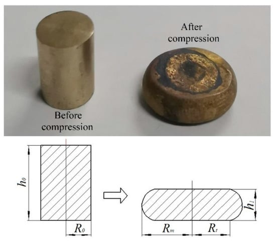
Figure 1.
Compression sample and schematic diagram.
Roebuck [29] proposed a criterion to evaluate the effect of friction through a barreling coefficient, which is expressed as:
where B is the barreling coefficient; h1 is the height of deformed specimen; RM is the maximum radius of the deformed specimen; R0 and h0 are initial radius and height of the specimen, respectively, see Figure 1.
When 1 < B ≤ 1.1, the differences between measured flow stress and the true flow stress are slight. The measured flow stress curves need not to be corrected. When B > 1.1, the measured flow stress curves must be corrected [30].
2.2. Method of Friction Correction
When the value of B is >1.1, the friction has a great influence on the measured flow stress. Friction correction of the measured flow stress should be carried out at this time. The corrected flow stress could be obtained through the method proposed by Gholamzadeh [31]:
where σ0 and σ are the flow stresses before and after friction correction, respectively; ε is the true strain corresponding to homogeneous deformation; m is a friction factor as follows:
where R1 is the average radius of deformed specimen, defined as ; RT is the top radius of the deformed specimen.
2.3. Hansel–Spittel Model
The thermo-viscoplastic constitutive model under hot condition is used in the finite element software FORGE 2011 to simulate bulk metal forming. One of the models mostly used for bulk metal forming is the Hansel–Spittel model. It could be used to describe the relationship between the flow stress σ, strain rate , strain ε and deformation temperature T. The model proposed by Hansel and Spittel is given as [32]:
where σ is the flow stress (MPa); e is the natural constant; T is the deformation temperature (°C); ε is the strain; is the strain rate (s−1); A, m1, m2, m3, m4, m5, m7, m8 and m9 are the material constants.
By taking the natural logarithm on both sides of the equation, Equation (6) can be transformed as:
3. Development of Constitutive Model
To develop the high-temperature constitutive model of HNi55-7-4-2 alloy, a hot-compression test needs to be implemented to obtain the practical stress-strain curves. Based on the stress-strain curves from the test, the theory presented in Section 2.3 could be used to determine the material parameters in the constitutive equation.
3.1. Hot-Compression Experiment Process and Results
The chemical composition of HNi55-7-4-2 alloy investigated in the current work is given in Table 1. Its microstructure is shown in Figure 2. Where the matrix is β phase, the strengthening phases are distributed on the β-phase matrix in particulate and massive shape. The strengthening phases on the longitudinal section are under interrupted distribution along the direction of extrusion. The β phase is usually hard and brittle at room temperature. Therefore, the HNi55-7-4-2 alloy is more suitable for hot forming process, such as hot forging.

Table 1.
The chemical composition of as-extruded HNi55-7-4-2 alloy (mass fraction, %).
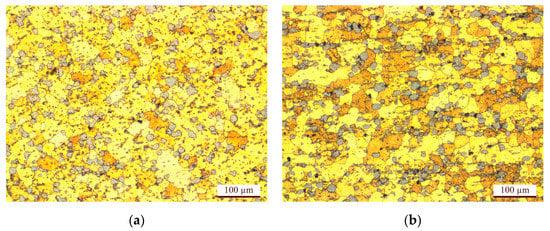
Figure 2.
Microstructures of as-extruded HNi55-7-4-2 alloy: (a) cross section; (b) vertical section.
The specimens used in the hot-compression test from an extruded HNi55-7-4-2 alloy cylinder, offered by Luzhou Long River Mechanical Company Ltd., Luzhou, China. The specimens are Φ8 × 12 mm cylinders prepared through low-speed wire cutting of the extruded cylinder.
The hot-compression test was carried out on a thermal simulator (Gleeble-3500, Dynamic Systems Inc., New York, NY, USA). To mitigate the effect of friction on the experimental result, graphite lubricant was coated on two ends of the specimens. At a heating rate of 10 °C/s, the specimens were heated to experiment temperature 600, 650, 700, 750 and 800 °C, respectively. Each experiment temperature was held for 180 s. The experiment strain rates were set as 0.01, 0.1, 1 and 10 s−1, respectively. The specimens were deformed to the height reductions of 60% with the true strain of 0.9.
The experiment’s resulting data, such as the values of flow stress, strain, stroke and force, were collected through the computer control system of the thermal simulator automatically.
The practical stress-strain curves of HNi55-7-4-2 alloy under various deformation conditions were determined based on the values of flow stress and strain obtained from the experiment, as shown in Figure 3.
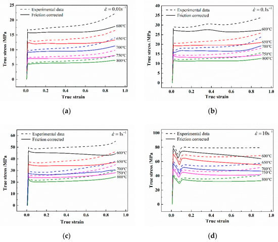
Figure 3.
The true strain-stress curves of HNi55-7-4-2 alloy before and after friction correction at the strain rate of: (a) , (b) , (c) , (d) .
It can be seen that the effects of deformation temperature, strain rate and strain on flow stress of HNi55-7-4-2 alloy are remarkable. At a certain strain rate, the stress will decline with the temperature rise. At a fixed temperature, the stress will rise with the increase of strain rate. It can be said that HNi55-7-4-2 alloy is a material with negative thermal sensitivity and positive strain rate sensitivity. Then, the stress-strain curve obtained by thermal simulator is used to develop the Hansel–Spittel constitutive model. In order to verify the accuracy of the model, the force-stroke curves simulated by the developed constitutive model is compared with the experimental force-stroke data. The details will be presented in Section 3.4.
3.2. Friction Correction
The stress-strain curves of HNi55-7-4-2 alloy at various temperatures and strain rates were obtained through the hot-compression test, as those presented in Figure 3 (dot line). According to Section 2.1, it is necessary to evaluate the effect of friction on stress-strain curves based on a barreling coefficient.
With measured sizes of deformed specimens under various deformation conditions, the values of the barreling coefficient B for specimens were calculated through Equation (1), given in Table 2. This shows that all the values of B are > 1.1. Therefore, the obtained flow stress curves of HNi55-7-4-2 alloy have to be corrected.

Table 2.
Value of B under various deformation conditions.
Using Equations (2)–(5), the friction correction of the true stress-strain curves obtained through the experiment was implemented. The correction results are shown in Figure 3 (solid line). It can be seen that the corrected flow stress values are much lower than the measured ones. In addition, the effect of the friction increases with the increasing strain and strain rate as well as decreasing deformation temperature.
3.3. Development of Hansel–Spittel Constitutive Model
The thermal deformation behaviors of HNi55-7-4-2 alloy depend on temperature T, strain rate and strain ε. With the friction corrected stress-strain curves and theory described in Section 2.3, the high-temperature constitutive model of HNi55-7-4-2 alloy was developed based on the Hansel–Spittel model.
3.3.1. Determination of m3 and m8
When the deformation temperature T and strain ε are of certain values, is a constant, which could be set as L1. Equation (7) can be transformed into Equation (8):
Here, S1 = m3 + m8T is set. The stress data with the strain ranging from 0.1 to 0.8 and interval being 0.1 at all deformation conditions were substituted into Equation (8). The scatter diagram of and at each deformation temperature was drawn and linearly fitted. The fitting results are shown in Figure 4, taking the results for T = 600 °C, T = 700 °C and T = 800 °C as examples. The slope of fitting line was the S1 value at the corresponding deformation condition.

Figure 4.
linear fitting curves at the temperature of: (a) 600 °C, (b) 700 °C, (c) 800 °C.
The relationship between S1 and T for various strain values can be obtained. The mean values of parameters m3 and m8 can be acquired from the intercept and slope of the lines, as shown in Figure 5.
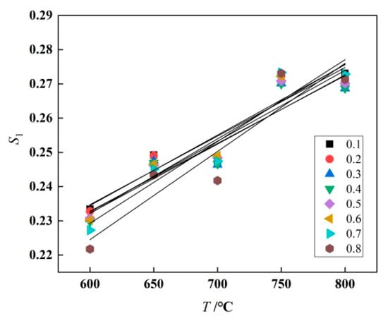
Figure 5.
S1-T Linear fitting curve.
3.3.2. Determination of m1, m5 and m9
When the values of strain rate and strain ε are constants, is a constant, set as L2. Equation (7) can be transformed into Equation (9):
Here, is set. The stress data with the strain ranging from 0.1 to 0.8 and interval being 0.1 at all deformation conditions were fitted in the function form of . The mean value of m9 can be obtained by determining mean value of fitting coefficient of ln T. The fitting results by taking and as examples are shown in Figure 6. The relationship between S2 and ln (1 + ε) for various strain rate values can be obtained. The mean value of m5 can be acquired from the slope of the lines. The mean value of m1 can be determined from the intercept of the lines and the obtained m8 value.
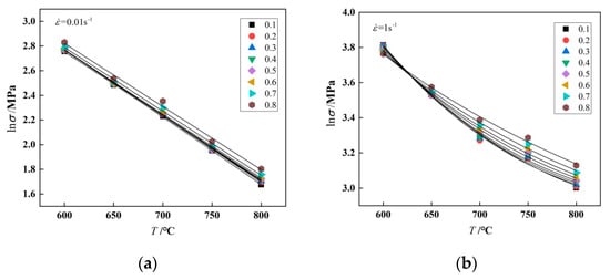
Figure 6.
fitting curve as a specified function at the strain rate of: (a) , (b) .
3.3.3. Determination of m2, m4, m7 and A
With fixed values of the strain rate and deformation temperature T, parameter L3 will be a constant, which is defined as . Equation (7) can be transformed into Equation (10):
The stress data with the strain ranging from 0.1 to 0.8 and interval being 0.1 at all deformation conditions were fitted in function form of Equation (10), to obtain the fitting coefficients at various temperatures. The mean values of m2, m4 and m7 were obtained correspondingly. Substituting the stress-strain data and the obtained values of m1~m9 into Equation (6), the mean value of A can be determined.
3.3.4. Obtaining Hansel–Spittel Constitutive Model
At this point, all of the material constants for the Hansel–Spittel high-temperature constitutive model are determined, as given in Table 3. The developed Hansel–Spittel constitutive model is described by Equation (11):

Table 3.
Values of material constants based on Hansel–Spittel model.
3.4. Verification of Constitutive Model
Through the developed high-temperature constitutive model (see Equation (11)), the values of flow stress under various deformation conditions could be predicted. The predicted flow stress values were compared with those obtained from a hot-compression test to verify the proposed constitutive model, as shown in Figure 7. It can be seen that the flow stress predicted through the constitutive model agrees with the experimental result well.
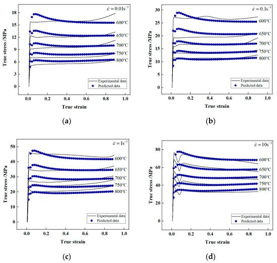
Figure 7.
Comparison between experimental and predicted flow stress using the Hansel–Spittel model at four strain rates: (a) , (b) , (c) , (d) .
Three statistical parameters—average absolute relative error (AARE), correlation coefficient (R) and root mean square error (RMSE)—were introduced here to evaluate the validity and prediction accuracy of the proposed constitutive model. The definition formulae of three statistical parameters are as follows:
where n is the number of data used in this work; Ei and Pi are experimental flow stress from experiment and predicted flow stress, respectively; and are the mean values of Ei and Pi, respectively.
The correlation coefficient R denotes the power of linear relation between experimental value and predicted value. The higher value of R does not always indicate a better performance since the tendency of the model could be biased. AARE is an unbiased statistical parameter which can accurately estimate the predication performance of models. RMSE is a prediction accuracy measurement used to estimate the deviation of predicted value from experimental value. The smaller the values of AARE and RMSE, the higher the model prediction accuracy will be.
The values of AARE, R and RMSE between experimental results and predicted ones from the Hansel-Spittel constitutive model are 5.6791%, 0.9912 and 2.6456 MPa, respectively. This verifies the prediction capability of the proposed constitutive model.
To validate the application of the developed Hansel–Spittel constitutive model to finite element numerical simulation for practical engineering analysis, the proposed model was used in the finite element software FORGE. Numerical simulation for 20 groups of hot-compression tests was implemented according to the experiment setting presented in Section 3.1. The simulation parameters were set as shown in Table 4.

Table 4.
Simulation parameters.
The force-stroke curves from finite element numerical simulation were compared with those from the experiment (see Section 3.1) at various deformation conditions. The comparison results are presented in Figure 8.
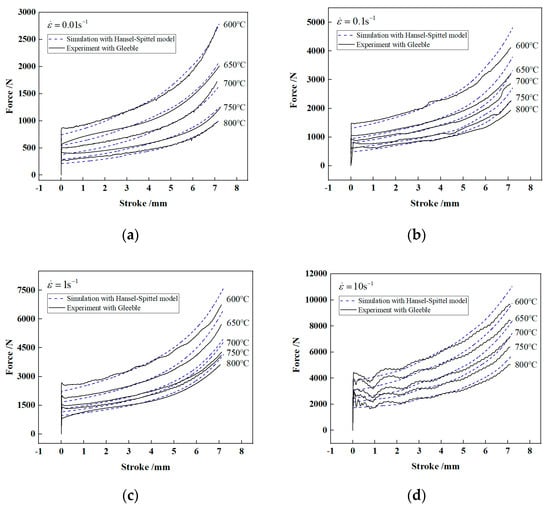
Figure 8.
Force vs. stroke plot from experiment and simulation under four strain rates: (a) , (b) , (c) , (d) .
It can be seen, as a whole, the force-stroke curves obtained through numerical simulation agrees with those from the experiment. Table 5 presents the values of AARE between the experimental results and the simulated ones under various deformation conditions. The maximum error value is 10.89% at 700 °C and 0.01 s−1, the minimum one is 3.98% at 600 °C and 10 s−1, and the mean error is 6.09%. This shows that the proposed Hansel–Spittel constitutive model of HNi55-7-4-2 alloy can be applied to finite element simulation with high accuracy.

Table 5.
Average absolute relative error (AARE) between experimental and simulated results at various deformation conditions.
Based on the validation of model application to numerical simulation, the proposed constitutive model could be used for the finite element simulation of a practical manufacturing process, see Section 4.2.
4. Application of High-Temperature Constitutive Model of HNi55-7-4-2 Alloy
This section presents a practical engineering application of the developed Hansel–Spittel high-temperature constitutive model of HNi55-7-4-2 alloy. The constitutive model was utilized to numerically simulate and analyze the hot precision forging process of synchronizer ring. A process experiment was carried out to validate the numerical simulation results.
4.1. Hot Precision Forging Process
A synchronizer ring made of HNi55-7-4-2 alloy is shown in Figure 9. This part is of complex structure; 36 combing teeth are uniformly distributed at three segments along the outer circumference of the ring. The addendum circle diameter D is 82.45 mm; 6 rectangular teeth are uniformly distributed on the inner circumference, with 3 convex keys set outside. The internal surface is a circular conical surface and the taper angle is 7.5°.

Figure 9.
Structure of synchronizer ring: (a) 3D model, (b) actual part.
The process flow of this synchronizer ring is as follows: smelting—continuous casting and rolling of copper rod—hot extrusion of copper tube—sawing—medium-frequency induction heating—hot precision forging—machining. The key step is the hot precision forging, especially the forging of the combing teeth, rectangular teeth and convex keys. Besides ensuring the filling of forgings, forging defects such as folding and cracking should be prevented.
Based on previous experience, two hot precision forging processes were designed for numerical simulation, comparing and analysis. The two process plans are illustrated in Figure 10. In plan 1, the billet is placed on the step plane of the bottom die and localized with the addendum circle of the tooth profile of the bottom die. Billet size: outer diameter D2 is 79.8 mm, inner diameter d2 is 65.5 mm, and height h2 is 13.5 mm. In plan 2, the billet was placed on the bottom of the bottom die and localized with the side face of the step. Billet size: outer diameter D3 is 73.4 mm, inner diameter d3 is 61.5 mm, and height h3 is 17.5 mm.

Figure 10.
Two hot precision forging process plans: (a) Plan 1, (b) Plan 2.
4.2. Numerical Simulation of Hot Precision Forging
4.2.1. Finite Element Modelling
Finite element modelling was implemented first so as to carry out numerical simulation of the hot precision forging process of the synchronizer ring. With the 3D model of die and billet created by commercial software UG8.0, the codes FORGE 2011 was used to set up a finite element model of hot precision forging, as shown in Figure 11.
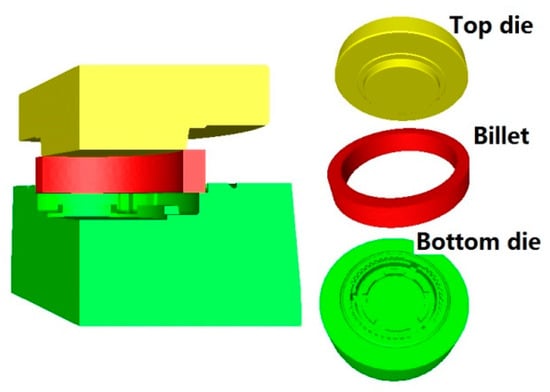
Figure 11.
Finite element model.
The developed Hansel–Spittel constitutive model was applied to the material property setting. Due to the symmetry, only one third of the 3D model was used for simulation to save computing time, as shown in Figure 11. The parameters used for numerical simulation are displayed in Table 6.

Table 6.
Parameters for numerical simulation.
4.2.2. Numerical Simulation Analysis
Based on the numerical simulation of the hot precision forging process for the synchronizer ring, the metal flow and forging filling were analyzed and compared for the two forming plans.
Figure 12a illustrates the force-stroke curve during the hot precision forging process of the synchronizer ring in plan 1. The process can be divided into three stages according to the force change. In stage 1, the top die was inserted into the inner bore of the billet, the alloy material was thrown into side wall and convex key cavity along axial direction. With the extrusion of the top die, a small part of the metals flowed into the gear cavity gradually, as shown in Figure 12b. In stage 2, the cavities for teeth, convex key and side wall were gradually filled with material. The bottom material flowed radially and formed rectangular teeth and inner flash. The top metals passed through the flash land to form an outer flash. In this stage, the material from two directions filled the junction section between the convex key and side wall. This may lead to a folding defect, see Figure 12c. In stage 3, with the top die pressing down constantly to the specified stroke, the forming force kept the rise. To ensure the filling of forging, a forging-die resistance slot is set on the bottom die. It prevents material flowing out from the flash land and formed outer flash. Meanwhile, material will flow out from the rectangular teeth cavity and formed inner flash. The folding defect may therefore appear around the rectangular teeth, see Figure 12d. The numerical simulation result of plan 1 showed that an obvious folding defect occurred at the junction between the convex key and side wall, as shown in Figure 12e.
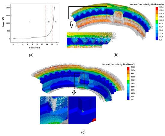
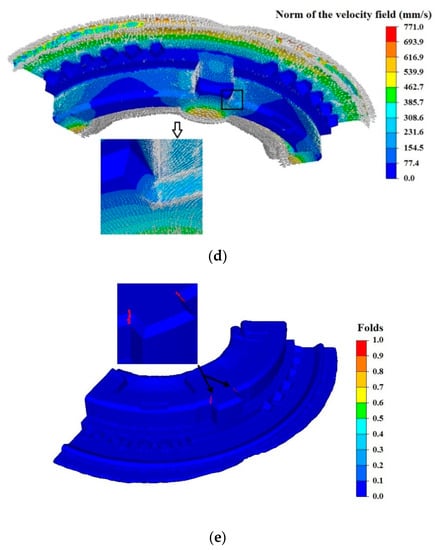
Figure 12.
Numerical simulation of process plan 1: (a) curve of force vs. stroke, (b) velocity distribution in stage 1, (c) velocity distribution in stage 2, (d) velocity distribution in stage 3, (e) folds distribution in the last simulation step.
The force-stroke curve of plan 2 is shown in Figure 13a. According to the force change, the process can be divided into three stages. In stage 1, the material was thrown into the rectangular teeth cavity, and the top die was inserted into inner bore of the billet (see Figure 13b). In stage 2, the top die continued to press down, a small part of material flowed into the convex key cavity gradually (Figure 13c). In stage 3, the material filled the teeth and convex key cavities. The filling of teeth mainly depended on radial material flow. The material filling the convex key cavity was from both radial and axial flow; see Figure 13d. The numerical simulation of Plan 2 presented a reasonable material flow at the junction between the convex key and side wall. It prevented the folding defect like that in Plan 1 from appearing. In the numerical simulation of plan 2, the folding defect occurred only at the inner flash (see Figure 13e).
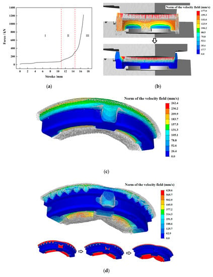
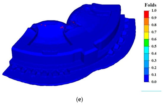
Figure 13.
Numerical simulation of process plan 2: (a) curve of force vs. stroke, (b) velocity distribution in stage 1, (c) velocity distribution in stage 2, (d) velocity distribution in stage 3, (e) folds distribution in the last simulation step.
4.3. Process Experiment
The billet used in the process experiment was prepared through cutting a hot extrusion tube (see Figure 14a). According to the billet size setting in the two process plans for numerical simulation in Section 4.1, two sizes of billets were prepared to implement the two process plan experiments. The billet was heated by a natural gas heating furnace. Hot precision forging was conducted on a numerical-control electric screwing press (see Figure 14b). Before forging, the die (Figure 14c) was preheated within the temperature range of 250–300 °C, and then sprayed with water-based graphite lubricant.
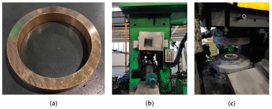
Figure 14.
Preparation before the process experiment: (a) billet, (b) numerical-control electric screwing press, (c) Die.
The process experiment results are shown in Figure 15. In the experiment of plan 1, obvious folding defects were found at the junction between the convex key and side wall of the synchronizer ring, as shown in Figure 15a.
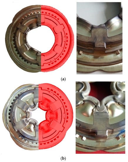
Figure 15.
Process experiment results: (a) process plan 1, (b) process plan 2.
As for the synchronizer ring formed in the experiment of process plan 2 (Figure 15b), the folding defect only occurred at the inner flash. No folding defect appeared at other parts. The forging was fully filled.
The experimental results of the two process plans validate the numerical simulation prediction presented in Section 4.1. It shows the proposed Hansel–Spittel high-temperature constitutive model could be applied to practical engineering analysis well.
5. Conclusions
In the current investigation, based on the practical stress-strain curves, the Hansel–Spittel high-temperature constitutive model was developed for a new type of wear-resistant alloy, HNi55-7-4-2. With friction effect correction, the true stress-strain curve of HNi55-7-4-2 alloy was obtained through a hot-compression test at temperature of 600–800 °C and strain rate of 0.01–10 s−1.
Based on the developed Hansel–Spittel constitutive model, flow stress values and force-stroke curves of HNi55-7-4-2 alloy were predicted and numerically simulated, respectively. The predicted and simulated results agreed with those from an experiment well. This verified the proposed Hansel–Spittel constitutive model.
The proposed Hansel–Spittel constitutive model was used to numerically simulate the hot precision forging of a synchronizer ring. The simulation results were validated by a process experiment. It was shown that the developed Hansel–Spittel constitutive model of HNi55-7-4-2 alloy could be reasonably applied to practical engineering analysis, in order to guide practical production.
The Hansel–Spittel high-temperature constitutive model developed in the current work makes it possible to implement the theoretical and engineering analysis of HNi55-7-4-2 alloy.
Author Contributions
Data collection and model construction, Q.L.; funding acquisition, Q.L., X.Z. and P.L.; writing-original draft, Q.L. and X.L.; writing-review and editing, Q.L., P.D., and P.L. All authors have read and agreed to the published version of the manuscript.
Funding
This work was funded by the Chongqing Basic Science and Advanced Technology Research Program (grant number cstc2017jcyjAX0175), Science and Technology Research Program of Chongqing Municipal Education Commission (grant numbers KJQN201900836, KJZD-M201900802 and KJZD-K201800801), and The Open Research Fund Program of Manufacturing Equipment Mechanism Design and Control Chongqing Key Laboratory (CTBU-KFJJ2018093 and CTBU-KFJJ2019078).
Acknowledgments
The authors sincerely appreciate the support of material used for experiments from the Luzhou Long River Mechanical Company Ltd., Luzhou, China.
Conflicts of Interest
The authors declare no conflict of interest.
Nomenclature
| Symbol/Acronym | Full Name | Symbol/Acronym | Full Name |
| B | Barreling coefficient | m | Friction factor |
| h1 | Height of deformed specimen (mm) | R1 | Average radius of deformed specimen (mm) |
| RM | Maximum radius of the deformed specimen (mm) | RT | Top radius of the deformed specimen (mm) |
| R0 | Initial radius of the specimen (mm) | T | Deformation temperature (°C) |
| h0 | Height of the specimen (mm) | A, m1, m2, m3, m4, m5, m7, m8, m9 | Material constants (bcc) |
| σ0 | Flow stresses before friction correction (MPa) | β | Brass beta-phase |
| σ | Flow stresses after friction correction (MPa) | D | Addendum circle diameter (mm) |
| ε | True strain | D2*d2*h2 | Billet size of plan 1 (mm) |
| Strain rate (s−1) | D3*d3*h3 | Billet size of plan 2 (mm) |
References
- Ashhab, M.D.S.; Breitsprecher, T.; Wartzack, S. Neural network based modeling and optimization of deep drawing—Extrusion combined process. J. Intell. Manuf. 2012, 25, 77–84. [Google Scholar] [CrossRef]
- Zhao, J.; Luo, S.-M.; Li, F.-Q.; Xu, C.-B. Multi-field coupling finite element analysis for determining the influence of temperature field on die service life during precision-forming process of steel synchronizer ring. J. Mech. Sci. Technol. 2017, 31, 3249–3254. [Google Scholar] [CrossRef]
- Lin, Y.C.; Chen, X.-M. A critical review of experimental results and constitutive descriptions for metals and alloys in hot working. Mater. Des. 2011, 32, 1733–1759. [Google Scholar] [CrossRef]
- Li, H.-Y.; Li, Y.-H.; Wang, X.-F.; Liu, J.-J.; Wu, Y. A comparative study on modified Johnson Cook, modified Zerilli–Armstrong and Arrhenius-type constitutive models to predict the hot deformation behavior in 28CrMnMoV steel. Mater. Des. 2013, 49, 493–501. [Google Scholar] [CrossRef]
- Zhang, H.; Wen, W.; Cui, H.; Xu, Y. A modified Zerilli–Armstrong model for alloy IC10 over a wide range of temperatures and strain rates. Mater. Sci. Eng. A 2009, 527, 328–333. [Google Scholar] [CrossRef]
- Zerilli, F.J.; Armstrong, R.W. Dislocation-mechanics-based constitutive relations for material dynamics calculations. J. Appl. Phys. 1987, 61, 1816–1825. [Google Scholar] [CrossRef]
- Xu, Z.; Huang, F. Comparison of physically based constitutive models characterizing armor steel over wide temperature and strain rate ranges. Model. Simul. Mater. Sci. Eng. 2012, 20, 015005. [Google Scholar] [CrossRef]
- Mirzadeh, H.; Cabrera, J.M.; Najafizadeh, A. Modeling and Prediction of Hot Deformation Flow Curves. Metall. Mater. Trans. A 2011, 43, 108–123. [Google Scholar] [CrossRef]
- Rusinek, A.; Klepaczko, J.R. Shear testing of sheet steel at wide range of strain rates and a constitutive relation with strain-rate and temperature dependence of the flow stress. Int. J. Plast. 2001, 17, 87–115. [Google Scholar] [CrossRef]
- Jankowiak, T.; Rusinek, A.; Wood, P. A numerical analysis of the dynamic behaviour of sheet steel perforated by a conical projectile under ballistic conditions. Finite Elem. Anal. Des. 2013, 65, 39–49. [Google Scholar] [CrossRef]
- Voyiadjis, G.Z.; Almasri, A.H. A physically based constitutive model for fcc metals with applications to dynamic hardness. Mech. Mater. 2008, 40, 549–563. [Google Scholar] [CrossRef]
- Lin, Y.C.; Zhang, J.; Zhong, J. Application of neural networks to predict the elevated temperature flow behavior of a low alloy steel. Comput. Mater. Sci. 2008, 43, 752–758. [Google Scholar] [CrossRef]
- Li, S.-S.; Zhou, J.; Zhang, M.-M.; Zhou, Y.-T.; Gong-Ye, F.-J.; Long, S.; Dong, X.-G.; Liang, Q. A comparative study at the flow behavior description of 2A14 alloy using BP-ANN and strain compensated Arrhenius model. Mater. Res. Express 2020, 6, 1265h1. [Google Scholar] [CrossRef]
- Ebrahimi, G.R.; Momeni, A.; Abbasi, S.M.; Monajatizadeh, H. Constitutive analysis and processing map for hot working of a Ni-Cu alloy. Met. Mater. Int. 2013, 19, 11–17. [Google Scholar] [CrossRef]
- Wen, T.; Liu, L.-T.; Huang, Q.; Chen, X.; Fang, J.-Z. Evaluation on prediction abilities of constitutive models considering FEA application. J. Cent. South Univ. 2018, 25, 1251–1262. [Google Scholar] [CrossRef]
- Quan, G.-Z.; Wen, H.-R.; Jia, P.; Zou, Z.-Y. Construction of processing maps based on expanded data by BP-ANN and identification of optimal deforming parameters for Ti-6Al-4V alloy. Int. J. Precis. Eng. Manuf. 2016, 17, 171–180. [Google Scholar] [CrossRef]
- Liu, S.; Pan, Q.; Li, H.; Huang, Z.; Li, K.; He, X.; Li, X. Characterization of hot deformation behavior and constitutive modeling of Al–Mg–Si–Mn–Cr alloy. J. Mater. Sci. 2018, 54, 4366–4383. [Google Scholar] [CrossRef]
- Ji, G.; Qin, F.; Zhu, L.; Li, Q.; Li, L. Dynamic Recrystallization Kinetics of Cu-0.36Cr-0.03Zr Alloy during Hot Compression. J. Mater. Eng. Perform. 2017, 26, 2698–2707. [Google Scholar] [CrossRef]
- Liu, N.; Li, Z.; Li, L.; Liu, B.; Xu, G.-y. Processing map and hot deformation mechanism of novel nickel-free white copper alloy. Trans. Nonferrous Met. Soc. China 2014, 24, 3492–3499. [Google Scholar] [CrossRef]
- Wang, M.-H.; Wei, K.; Li, X.-J.; Tu, A.-Z. Constitutive modeling for high temperature flow behavior of a high-strength manganese brass. J. Cent. South Univ. 2018, 25, 1560–1572. [Google Scholar] [CrossRef]
- Wang, Y.; Zhou, Y.; Xia, Y. A constitutive description of tensile behavior for brass over a wide range of strain rates. Mater. Sci. Eng. A 2004, 372, 186–190. [Google Scholar] [CrossRef]
- Samantaray, D.; Mandal, S.; Bhaduri, A.K. Constitutive analysis to predict high-temperature flow stress in modified 9Cr–1Mo (P91) steel. Mater. Des. 2010, 31, 981–984. [Google Scholar] [CrossRef]
- Zhao, Y.; Sun, J.; Li, J.; Yan, Y.; Wang, P. A comparative study on Johnson-Cook and modified Johnson-Cook constitutive material model to predict the dynamic behavior laser additive manufacturing FeCr alloy. J. Alloys Compd. 2017, 723, 179–187. [Google Scholar] [CrossRef]
- Martínez, H.V.; Coupard, D.; Girot, F. Constitutive model of the alloy 2117-T4 at low strain rates and temperatures. J. Mater. Process. Technol. 2006, 173, 252–259. [Google Scholar] [CrossRef]
- Chadha, K.; Shahriari, D.; Tremblay, R.; Bhattacharjee, P.P.; Jahazi, M. Deformation and Recrystallization Behavior of the Cast Structure in Large Size, High Strength Steel Ingots: Experimentation and Modeling. Metall. Mater. Trans. A 2017, 48, 4297–4313. [Google Scholar] [CrossRef]
- El Mehtedi, M.; Musharavati, F.; Spigarelli, S. Modelling of the flow behaviour of wrought aluminium alloys at elevated temperatures by a new constitutive equation. Mater. Des. (1980–2015) 2014, 54, 869–873. [Google Scholar] [CrossRef]
- Liang, Q.; Liu, X.; Li, P.; Zhang, X. Hot Deformation Behavior and Processing Map of High-Strength Nickel Brass. Metals 2020, 10, 782. [Google Scholar] [CrossRef]
- Chadha, K.; Shahriari, D.; Jahazi, M. An Approach to Develop Hansel–Spittel Constitutive Equation during Ingot Breakdown Operation of Low Alloy Steels. In Frontiers in Materials Processing, Applications, Research and Technology; Springer: Singapore, 2018; pp. 239–246. [Google Scholar]
- Roebuck, B.; Lord, J.; Brooks, M.; Loveday, M.; Sellars, C.M.; Evans, R.W. Measuring Flow Stress in Hot Axisymmetric Compression Tests. Mater. High Temp. 2006, 23, 59–83. [Google Scholar] [CrossRef]
- Luan, J.; Sun, C.; Li, X.; Zhang, Q. Constitutive model for AZ31 magnesium alloy based on isothermal compression test. Mater. Sci. Technol. 2013, 30, 211–219. [Google Scholar] [CrossRef]
- Gholamzadeh, A.; Karimi Taheri, A. The prediction of hot flow behavior of Al–6%Mg alloy. Mech. Res. Commun. 2009, 36, 252–259. [Google Scholar] [CrossRef]
- Chen, X.; Wang, N.; Ma, X.; Zhou, H. Hot deformation behaviour and Hansel-Spittel constitutive model of Cr5 alloy for heavy backup roll. Int. J. Comput. Mater. Sci. Surf. Eng. 2018, 7, 205–217. [Google Scholar] [CrossRef]
© 2020 by the authors. Licensee MDPI, Basel, Switzerland. This article is an open access article distributed under the terms and conditions of the Creative Commons Attribution (CC BY) license (http://creativecommons.org/licenses/by/4.0/).