Abstract
To enhance the abrasion resistance of TC4 titanium alloy and meet the demand for wear-resistant and corrosion-resistant friction pair materials for water-hydraulic components of marine equipment, the tribological properties of the material subsequent to ultrasonic rolling extrusion surface strengthening under seawater-lubricated conditions were investigated. The process of ultrasonic rolling machining was simulated and analyzed by the finite element method. The influence of process parameters on surface residual stress and surface roughness of TC4 was studied, and the appropriate range of process parameters was determined. The effects of key process parameters such as rolling times, static pressure, amplitude, and rotational speed on the surface properties of TC4 were investigated by the single-factor test method. Based on the response surface methodology, a prediction model of surface hardness and roughness of TC4 was constructed, and the process parameters were optimized and analyzed. The friction coefficient, wear amount, and wear rate of TC4 and CFRPEEK under seawater lubrication before and after strengthening were studied by wear tests. The wear morphologies of the specimens prior to and subsequent to strengthening were analyzed, and the friction and wear mechanisms were explored in depth. The results indicate that ultrasonic rolling extrusion surface strengthening process facilitates grain refinement in the surface layer of TC4, enhances surface hardness, and optimizes surface roughness, thereby improving its wear resistance. This is of guiding significance to the design and use of hydraulic components in seawater and has a promoting effect on the development of marine equipment.
1. Introduction
As a crucial resource treasure house on the Earth, the ocean houses abundant biological, mineral, and energy resources, and boasts enormous economic potential [1,2,3]. In the process of marine resource utilization, marine equipment such as offshore drilling equipment [4], manned submersibles, and deep-sea space stations [5,6] play a vital role. With its unique natural advantages, hydraulic transmission technology has been widely applied in marine equipment [7].
The physical and chemical properties of seawater are significantly different from those of conventional hydraulic oil. Specifically, salts and dissolved oxygen in seawater will trigger electrochemical corrosion, while corrosive media rich in chloride ions (Cl−), sulfates, and other corrosive substances will accelerate the surface corrosion of metal materials [8]. Therefore, commonly used ferrous metal materials cannot be directly used in seawater, and the physical and chemical properties of seawater pose serious wear and corrosion challenges to water hydraulic components [9,10]. In an effort to ensure the stable operation of water hydraulic components, their auxiliary materials must exhibit both corrosion resistance and wear resistance [11,12]. Among various materials, TC4 titanium alloy is the preferred corrosion-resistant material for extreme marine equipment, thanks to its excellent corrosion resistance, high strength, and low density [13]. However, due to its unique metallographic structure, TC4 exhibits relatively low hardness and poor wear resistance. Furthermore, heat treatment methods are ineffective for improving its surface hardness, which limits its application as an auxiliary material [14].
To meet the demand for wear-resistant and corrosion-resistant friction pair materials in water-hydraulic components of marine equipment, this study aims to improve the wear resistance of TC4 and adopts ultrasonic rolling extrusion technology for its surface treatment. Ultrasonic rolling technology is formed by the integration of rolling technology and ultrasonic vibration technology. Through grain structure refinement and surface irregularity smoothing, microscopic plastic deformation of the material is achieved. Its surface performance is significantly enhanced [15,16], and the surface integrity of metallic materials is thereby ensured [17,18]. Extensive research on this technology has been carried out by domestic and international experts. John et al. [19] made a comprehensive review of the ultrasonic surface rolling process, discussed the mechanism of the process in the process of grain refinement and gradient microstructure formation, and summarized its influence on various mechanical properties of materials, including hardness, tensile property, fatigue property, wear resistance, residual stress, corrosion resistance, and surface roughness. Zhang et al. [20] performed comparative tests of the ultrasonic surface rolling process (USRP) on the Ti-6Al-4V alloy. It was found that USRP parameters corresponding to stable dynamic behaviors are favorable for achieving superior surface roughness. In contrast, the regulation of ultrasonic amplitude to induce unstable dynamic behaviors results in a marked deterioration of surface quality, accompanied by a significant increase in the extent of plastic deformation. Liu et al. [21] studied the influence of ultrasonic rolling technology on the corrosion resistance of metals, and the results illustrated that the corrosion resistance of metal samples after ultrasonic rolling treatment significantly improved and revealed the relationship between the microstructure of metal samples and corrosion resistance. Wang et al. [22,23,24] integrated simulations with experiments to explore the influence regularity of ultrasonic rolling extrusion strengthening on the surface hardness and residual stress of 42CrMo steel. Their findings demonstrated that the simulated values of the machining process were in good agreement with the experimental data, which accurately revealed the residual stress distribution regularity of 42CrMo steel.
Taking TC4 as the research subject, this study addresses its issues of relatively low hardness and inadequate wear resistance. Ultrasonic rolling extrusion technology is employed for surface strengthening, while response surface methodology is adopted to optimize the process parameters, thereby determining the optimal parameter combination. The wear tests of TC4 and Carbon Fiber Reinforced Polyether Ether Ketone (CFRPEEK) were carried out on a special ring pin wear test rig. The friction coefficient, wear amount, and wear rate of TC4 and CFRPEEK were studied before and after strengthening under seawater lubrication conditions, and the wear resistance and friction reduction effect of ultrasonic rolling were evaluated. This study proposes a surface strengthening method to enhance TC4 wear resistance. It provides guiding value for designing and applying friction pairs in seawater hydraulic components and facilitates the development of marine equipment.
2. Simulation Analysis of Ultrasonic Rolling of TC4
2.1. Emulation Settings
The finite element simulation method was employed to perform simulation analysis on the ultrasonic rolling extrusion process. The TC4 was simplified, with its length set to 20 mm, diameter to 35 mm, and the rolling ball head diameter to 2 mm. During the simulation, the TC4 material was assumed to be isotropic by default.
The size and density of grid cells are primarily governed by seed parameters, with global seed settings enabling uniform control over the grid density of the entire model. The geometric characteristics and structural regularity of TC4 make it suitable for hexahedral meshing in ABAQUS 2022, which enhances computational accuracy. The rolling ball head is made of high-strength tungsten steel, whose stiffness is much higher than that of the TC4 matrix. In an effort to simplify the calculation model, the rolling ball head is set as an analytical rigid body, and meshing of the rolling ball head is not required. After optimizing the settings, the grid cell size is determined to be 0.05 mm, the total number of grids in the simulation model is 84,576, and the grid division model of TC4 is illustrated in Figure 1.
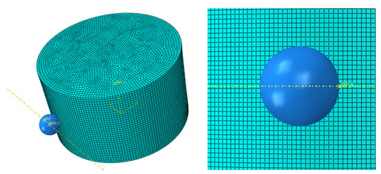
Figure 1.
Simulation model of ultrasonic rolling mesh generation.
The workpiece processed by ultrasonic rolling is made of TC4. Table 1 presents the physical parameters such as density, elastic modulus, Poisson’s ratio, and yield strength of TC4.

Table 1.
Physical parameters of TC4.
Johnson and Cook put forward the Johnson–Cook (J-C) model. The J-C model can clearly describe the influence of various factors on the mechanical behavior of materials. It is suitable for impact dynamics simulation and is mostly used to describe the stress–strain relationship of metals. The J-C model is given in Equation (1) [25]. The J-C model parameters of TC4 are shown in Table 2.
where is the flow stress; is the strain of the material, is the strain rate of the material, and is the reference strain rate of the material; , , and are the melting temperature, filtration temperature, and absolute temperature rise in the material.
Table 2.
J-C model parameters of TC4.
In the finite element simulation of TC4, an explicit dynamic solution method was employed for numerical modeling. The contact between the rolling ball head and TC4 was established using the penalty function algorithm. In the contact interaction settings, the normal contact was defined with the hard contact criterion to prevent penetration, while the tangential contact was modeled based on the penalty function method to simulate frictional behavior, with the friction coefficient set to 0.05 according to experimental results. In defining the contact pairs, the surface of the rolling ball head was designated as the master surface, and the TC4 surface was assigned as the slave surface. This configuration effectively simulates the interaction between the two contact surfaces during the actual machining process. The stress field reported in this study is not the instantaneous von Mises stress during loading, but rather the residual stress field after ultrasonic rolling treatment and complete unloading. This residual stress field was accurately obtained through a stepwise simulation strategy of “loading–unloading” implemented in the ABAQUS platform.
In the simulation of ultrasonic rolling and extrusion, the force applied by the rolling ball head to the workpiece surface is decomposed into the superposition of static pressure and dynamic vibration pressure. Since static pressure and amplitude cannot be applied simultaneously within a single analysis step, the vibration imposed on the rolling ball head is equivalently represented by static pressure, as formulated in Equation (2).
In the equation, represents the initial amplitude; and denote the amplitudes of the harmonic components, respectively. indicates the number of harmonics, and is the angular frequency of the ultrasonic wave.
The trajectory of the rolling ball head follows a sinusoidal wave pattern, which can be set as n = 1 and = 0.
represents the angular frequency of the ultrasonic wave. When the amplitude is 6 μm, the period is π × 10−2 s. The ultrasonic amplitude curve is shown in Figure 2.
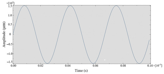
Figure 2.
Ultrasonic amplitude.
In the simulation of ultrasonic rolling, the setting of boundary conditions directly affects the simulation results. The constraint conditions for the TC4 are as follows: the translational and rotational degrees of freedom of TC4 in the X-axis and Y-axis directions are restricted, as is the translational degree of freedom in the Z-axis direction, while only the rotational degree of freedom around the Z-axis is reserved. For the rolling ball head, the degrees of freedom in the Y-axis and Z-axis directions are constrained so that it only undergoes ultrasonic vibration along the X-axis direction.
2.2. Result Analysis
The effects of static pressure, ultrasonic amplitude, and rotational speed on the residual stress and surface roughness of TC4 can be revealed via finite element simulation. This simulation thus provides a theoretical basis for guiding the optimization of the parameter range in ultrasonic rolling tests.
Figure 3, Figure 4 and Figure 5 illustrate the residual stress variation in TC4 under different process parameters. The simulation shows that the residual stress increases with increasing static pressure and amplitude, while the spindle speed shows the opposite trend (with static pressure ranging from 0 to 600 N and amplitude from 5 to 10 μm). Additionally, plastic deformation refines the surface grains of the workpiece and makes the dislocation distribution more uniform, thereby improving the surface hardness and fatigue resistance of the workpiece. At the same time, the residual stress does not exceed the yield strength of the material. The variation in surface residual stress of the TC4 with rotational speed is not significant; the maximum variation range is less than 8%, indicating that the effect of increasing the rotational speed on improving surface residual stress is relatively limited.
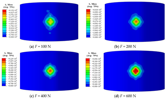
Figure 3.
Residual stress of TC4 under different static pressures.
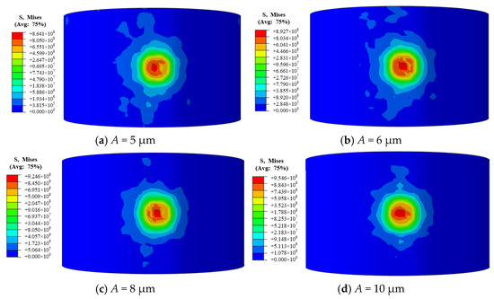
Figure 4.
Residual stress of TC4 under different amplitudes.
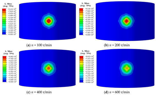
Figure 5.
Residual stress of TC4 at different rotating speeds.
The variation law of TC4 surface roughness with different process parameters is presented in Figure 6. Simulation results reveal that the surface roughness in the rolled zone of TC4 first decreases and then increases as static pressure, amplitude, and rotational speed change. When static pressure ranges from 0 to 600 N, amplitude is between 5 and 10 μm, and rotational speed is within 0 to 600 r/min, the surface roughness of TC4 reaches the optimal level, indicating superior surface performance within this parameter range.
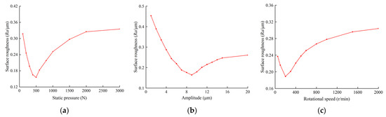
Figure 6.
Surface roughness under different process parameters. (a) Static pressure; (b) amplitude; (c) rotational speed.
3. Ultrasonic Rolling Test of TC4
3.1. Test Equipment and Parameters
ZAK4085D1 CNC machine tool (Shanghai Kerong Equipment Co., Ltd., Shanghai, China) and ultrasonic impact device are selected for the test. The physical objects of the ultrasonic rolling device and the rolling process are shown in Figure 7. The amplitude of the ultrasonic impact device is constant during the test.
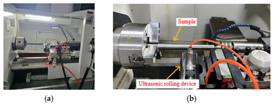
Figure 7.
Ultrasonic rolling device. (a) CNC machine tool; (b) rolling process.
Ultrasonic rolling extrusion process parameters significantly affect the surface properties of TC4, though their impacts on the strengthening effect vary in degree. The untreated TC4 bar has a diameter of 35 mm, initial hardness of 340 HV, and surface roughness Ra of 0.4864 μm. To investigate the specific effects of process parameters on TC4 surface properties, this study adopted the parameter ranges as shown in Table 3.
Table 3.
Ultrasonic roll strengthening parameters.
3.2. Effect of Process Parameters on Surface
In the ultrasonic rolling test, the key technological parameters such as static pressure, amplitude, and rotational speed have important effects on the surface hardness and surface roughness of TC4. Compared with its initial state, the surface hardness of TC4 has significantly improved, and the surface roughness has also significantly decreased.
Analysis of the data presented in Figure 8 indicates that surface hardness increases initially and then decreases with increasing static pressure, amplitude, and rotational speed. During the testing process, high-frequency impacts induce an elevation in dislocation density on the workpiece surface, which in turn facilitates grain refinement and the formation of a dense work-hardened layer, thereby significantly enhancing surface hardness. However, when these parameters exceed optimal levels, excessive plastic deformation occurs on the TC4 surface, leading to microstructural damage. This is accompanied by crack initiation in the excessively deformed regions; as these cracks propagate further, the strengthened and hardened layer of TC4 is ultimately compromised, resulting in a corresponding decrease in surface hardness.
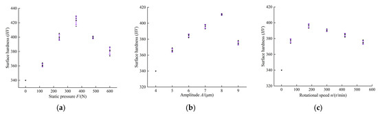
Figure 8.
Effect of different process parameters on surface hardness. (a) Static pressure; (b) amplitude; (c) rotational speed.
Analysis of the data presented in Figure 9 reveals that surface roughness exhibits a trend of first decreasing and then increasing with increasing static pressure, amplitude, and rotational speed. The flattening effect of the rolling ball effectively mitigates micro-irregularities on the TC4 surface, resulting in reduced surface roughness. However, when these parameters exceed optimal levels, excessive impact energy from the rolling ball induces vibration in TC4 during processing. This leads to surface material damage such as crack formation, consequently increasing surface roughness. As can be seen from Figure 9c, the minimum surface roughness of TC4 is measured as 0.2054 μm experimentally and simulated as 0.1889 μm, resulting in an error of 8.03% between the two. The relative error in the extent of roughness reduction is only 5.54%. The close agreement between experimental and simulation results is demonstrated, with the small relative error confirming the accuracy and reliability of the simulation model and outcomes.
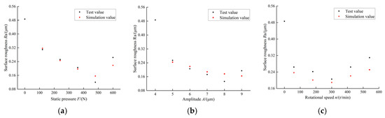
Figure 9.
Effect of different process parameters on surface roughness. (a) Static pressure; (b) amplitude; (c) rotational speed.
In the ultrasonic rolling test, the surface hardness and surface roughness of the workpiece are also significantly influenced by rolling times. The test results for surface hardness and surface roughness of TC4 under different rolling times are presented in Figure 10. Specifically, surface hardness first increases and then decreases with increasing rolling times, whereas surface roughness exhibits the opposite trend. When the number of rolling times is 3, surface hardness reaches a peak of 417 HV, and surface roughness attains a minimum of 0.1625 μm. Compared with unreinforced TC4, the surface hardness of the treated sample is increased by 22.64%, while its surface roughness is reduced by 66.59%.
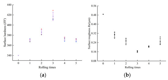
Figure 10.
Effect of rolling on (a) surface hardness and (b) surface roughness.
3.3. Response Surface Methodology Analysis
Response Surface Methodology (RSM) designs test plans based on statistical principles, utilizes test data to construct prediction models, optimizes interactions between variables, and then determines the optimal parameter combination. Regression analysis was performed on the experimental data using the least squares method, and response surface models were established to characterize the relationships between TC4 surface hardness, surface roughness, and their respective influencing factors. The standard form of these models is presented in Equation (5) [26]:
where Y is the predicted value of surface properties; β0 is the constant term coefficient; βi is the coefficient of the first order term; βij and βii are the quadratic term coefficients; wi and wj are the influencing factors; and εc is the error.
The prediction models for the surface hardness (HV) and surface roughness (Ra) of TC4 workpieces were obtained by the least square fitting method, and the models are shown in Equations (6) and (7), respectively.
In the formula, A is rolling times; B is static pressure, N; C is amplitude, μm; and D is the rotational speed, r/min.
To verify the accuracy of the TC4 surface performance prediction model, a significance level test was performed on the model. The specific test results are presented in Table 4 and Table 5.
Table 4.
Significance test for surface hardness regression equation.
Table 5.
Significance test for surface roughness regression equation.
As shown by the significance test results of the surface hardness regression equation in Table 4, the F-value of the second-order regression model for TC4 surface hardness was determined to be 2.47, while the p-value was calculated as 0.008 (F > F0.05, p < 0.01). The coefficient of determination R2 of the model was found to be 98.54%, indicating a strong linear correlation between the experimental data and the model-predicted values and demonstrating excellent model fit. The influence of process parameters on the model is reflected by the p-value, whereas their effect on surface hardness is characterized by the F-value. According to the regression equation presented in Table 4, the number of rolling passes and static pressure are identified as the most significant factors affecting the prediction model, with both parameters observed to have the strongest influence on the surface hardness of TC4. Amplitude is shown to be the next most influential factor, while spindle speed is found to have the least impact.
As indicated by the significance test results of the surface roughness regression equation in Table 5, the F-value of the second-order regression model for TC4 surface roughness is calculated as 2.45, and the corresponding p-value is determined to be 0.0095 (F > F0.05, p < 0.01). The coefficient of determination R2 is obtained as 97.43%, which demonstrates a strong linear correlation between the experimental data and the model predictions, accompanied by a small error. This result confirms the excellent fitting performance of the prediction model and verifies its reliability and accuracy in predicting the optimal process parameters. The degree of influence of the process parameters on the model results is reflected by the p-value, while their impact on surface roughness is characterized by the F-value. According to the regression equation presented in Table 5, static pressure and amplitude are identified as the two most significant factors affecting the surface roughness of TC4, followed by the number of rolling passes. Spindle speed is shown to have the least influence.
The residual distributions of the prediction models for TC4 surface hardness and surface roughness are presented in Figure 11. As shown in the figure, the predicted values are normally distributed along the regression curve, and the experimental results are found to be in close agreement with the predicted values. This further confirms the accuracy of the prediction models.
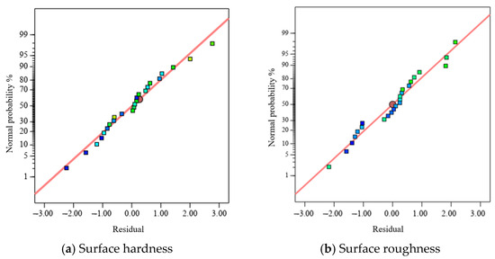
Figure 11.
Residual distribution of surface hardness and roughness.
The prediction model keeps two of the process parameters constant at their respective levels, and simulates and analyzes the influence of the other two process parameters on the surface hardness and surface roughness of TC4, so as to obtain the response surface chart for surface performance comparison. Based on the quadratic response surface prediction models for the surface hardness and surface roughness of TC4, the influence law of different process parameter combinations on TC4 surface performance can be derived, as presented in Figure 12.
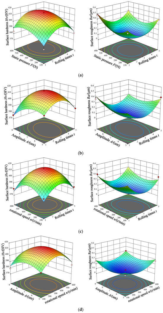
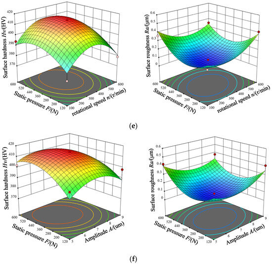
Figure 12.
Surface performance response surface and contour map for different process parameters. (a) Rolling times and static pressure, (b) rolling times and amplitude, (c) rolling times and rotational speed, (d) rotational speed and amplitude, (e) rotational speed and static pressure, and (f) amplitude and static pressure.
The influence patterns of process parameters, including rolling times, static pressure, amplitude, and rotational speed, on the surface hardness and surface roughness of TC4 are intuitively illustrated in Figure 12. It can be observed from the figure that the variation trend of the surface performance response surface under different process parameters is basically consistent with that of the ultrasonic rolling extrusion test. This further validates the reliability of the response surface prediction model in terms of optimizing process parameters. Through simulation analysis, it is determined that rolling times and static pressure exert the most significant influence on the surface properties of TC4, followed by amplitude, with rotational speed having the least influence.
Optimization analysis of process parameters was conducted using the prediction model established via RSM. It was predicted that the optimal surface properties of TC4 would be achieved under the optimal ultrasonic rolling extrusion parameter combination: 3 rolling times, static pressure of 402 N, amplitude of 7.8 μm, and rotational speed of 200 r/min. To systematically evaluate the reliability of the prediction model, comparative analysis was performed between the experimentally measured surface hardness and roughness data of TC4 and the predicted values. The relative errors were calculated, with results presented in Table 6.
Table 6.
Comparison of optimization prediction results with experimental results.
The optimized surface hardness predicted by RSM is 446.632 HV, while the tested surface hardness of TC4 is 451 HV, which is 32.65% higher than that of the untreated state, and the relative error is 0.978%. The surface roughness is 0.1428 μm, and the relative error is −3.51%. The results show that the prediction values of surface hardness and surface roughness of TC4 based on RSM are highly consistent with the experimental values, and the maximum relative error is less than 5%, which fully verifies the effectiveness and accuracy of the prediction model in the optimization of ultrasonic rolling strengthening process parameters.
Figure 13 illustrates the three-dimensional morphology and two-dimensional profile of TC4 before strengthening and under the optimized combination of process parameters. The surface roughness of TC4 after strengthening is reduced by 70.64% from 0.4864 μm to 0.1428 μm, and the surface quality of TC4 has been improved significantly.
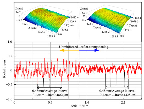
Figure 13.
Three-dimensional morphology and surface roughness of TC4.
3.4. Microstructure Analysis
The surface microstructure along the depth direction of TC4 specimens subjected to ultrasonic rolling extrusion was observed using a metallographic microscope. Image characterization was conducted at magnifications of 200× and 1000×, with the results presented in Figure 14. From the 200× magnified images, it can be observed that the grains exhibit a gradient variation from the surface layer to the core matrix of the TC4. Severe plastic deformation is generated in the material surface layer, forming a plastic deformation layer. When observed toward the core, a transition layer is present, within which the core matrix region is located.
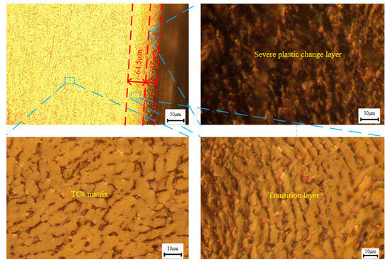
Figure 14.
Microstructure of TC4 after ultrasonic rolling.
In the severe plastic deformation layer, dislocation tangles are generated within TC4 due to ultrasonic high-frequency vibration and rolling force [27,28]. The formation of nano-grains in dislocation tangling regions is promoted by compressive stress, resulting in a more compact arrangement of the surface microstructure of TC4 and significant grain refinement [29,30]. In the transition layer, as the mechanical force induced by ultrasonic rolling extrusion gradually weakens, the degree of grain refinement is correspondingly reduced. The core matrix of TC4 is primarily composed of irregular polygonal or equiaxed grains. Since ultrasonic rolling extrusion acts mainly on the specimen surface, minimal influence is exerted on the core microstructure; thus, microstructural changes remain limited, with the original grain structure retained. The properties of metallic materials are closely related to their microstructures: the finer the grains, the better the material’s performance in terms of strength, hardness, and other properties. Consequently, the surface quality of TC4 is significantly improved by ultrasonic rolling extrusion treatment.
Figure 15 depicts the hardness distribution of TC4 at different depths from the surface under the optimized combination of process parameters. The surface hardness is approximately 458 HV. From this, it can be calculated that the hardness range of the plastic deformation layer is 412.2~458 HV; the depth corresponding to a hardness of 415 HV is 45 μm. Therefore, the depth of the plastic deformation layer of TC4 is about 40.5 μm. The average hardness of the TC4 core matrix is 342 HV, the minimum hardness of the effective hardened layer is 372.2 HV, and the corresponding depth is 110 μm (373 HV). Therefore, the transition layer of TC4 is defined as the interval from 45 μm to 110 μm. The results show that ultrasonic rolling treatment can effectively induce plastic deformation in the surface layer of TC4, refine grains, and enhance its surface hardness.
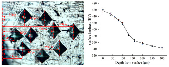
Figure 15.
Surface hardness of TC4 at different depths from the surface.
4. Friction and Wear Test of Strengthened TC4 Under Seawater Lubrication
4.1. Test Materials and Devices
The one-ring and two-pin wear test device designed in this study is shown in Figure 16. The device is mainly composed of a variable-frequency motor, a torque tachometer, a transmission shaft, a sample box, a loading module, and a data acquisition module. TC4 specimens that had undergone ultrasonic rolling extrusion strengthening were employed as metal ring samples, while unreinforced specimens were used as controls. The pin samples were fabricated from CFRPEEK material.
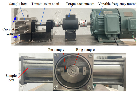
Figure 16.
One-ring and two-pin wear test device.
The wear tests in this study were designed, performed, and evaluated in accordance with the fundamental principles and methods specified by the ASTM G77-17 standard. Although the typical block-on-ring configuration is prescribed in the standard, its core experimental principles are fully aligned with the ring-on-pin configuration employed in this work, in which a rotating ring specimen and a stationary pin (or block) specimen are subjected to sliding wear under a constant load. Under conditions of controlled load, regulated sliding velocity, and simulated seawater lubrication, the tribological properties of TC4 were systematically assessed both before and after ultrasonic rolling extrusion treatment. The experimental methodology is grounded in clearly established standardized protocols, thereby ensuring the scientific validity, comparability, and reproducibility of the obtained results.
To simulate the artificial seawater environment, artificial seawater was prepared by dissolving 1 kg of sea salt in 30 L of purified tap water. During the friction and wear test, the spindle rotational speed was set at 460 r/min, corresponding to a linear velocity of 0.84 m/s. A constant load of 400 N was applied, and the test duration lasted for 180 min. To ensure the reliability of the experimental data, a new specimen was used for each test group, and the tests were repeated three times to obtain average values. The reported friction coefficient and wear loss data are based on the mean values calculated from these three repeated trials.
4.2. Comparison of Friction and Wear Results
The typical variation curves of the friction coefficient with time for the TC4-CFRPEEK mating pairs are presented in Figure 17. As can be observed from the figure, a significant running-in stage is experienced by both TC4-CFRPEEK mating pairs at the initial stage of the test. During this stage, the friction coefficient decreases sharply and then tends to stabilize, with no obvious fluctuations detected. Specifically, the running-in time of TC4 is approximately 35 min both before and after strengthening. After reaching a stable state, the friction coefficient of unreinforced TC4 is measured as 0.07891, while that of the strengthened TC4 is 0.05739. Compared with the unreinforced counterpart, the TC4-CFRPEEK mating pair with strengthened TC4 achieves a 27.27% reduction in friction coefficient. This result indicates that ultrasonic rolling extrusion strengthening treatment significantly improves the wear resistance of TC4.
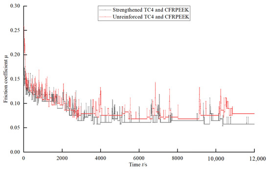
Figure 17.
Variation curve of friction coefficient with time.
As the contact area of the ring and pin specimens expand with wear, the specific pressure between the two change accordingly. The wear scar width of the CFRPEEK sample during the wear process is shown in Figure 18. At the 5 min test point, the wear scar width of the CFRPEEK ground against the unreinforced TC4 is 2.85 mm, and that ground against the strengthened TC4 is only 2.01 mm. At the end of the test, the wear scar widths of CFRPEEK paired with unreinforced and strengthened TC4 were 8.57 mm and 5.97 mm, respectively, further confirming the positive effect of TC4 surface strengthening treatment on reducing the wear of CFRPEEK.
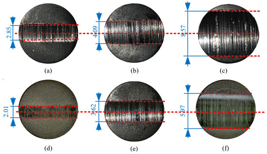
Figure 18.
Wear mark width of CFRPEEK pin specimen. (a–c) Grinding with unreinforced TC4 for 5 min, 25 min, and 180 min, respectively; (d–f) grinding with strengthened TC4 for 5 min, 25 min, and 180 min, respectively.
The contact pressure results of the TC4-CFRPEEK mating pairs are presented in Figure 19. During the initial running-in stage of the test, rapid changes in the wear scar width of CFRPEEK were observed. For the strengthened TC4 mating pairs, the contact pressure was reduced from 20.88 MPa to 11.56 MPa, while for the unreinforced counterparts, it decreased from 14.42 MPa to 8.43 MPa. As wear progressed, continuous expansion of the worn surface width was noted, with the initial line contact gradually evolving into surface contact. A larger contact area was thereby provided, facilitating the formation of a water film at the contact interface. With the effective formation of the water film, significant improvement in the lubrication state between the friction pairs was achieved, which in turn led to an effective reduction in the friction coefficient of the friction pairs.
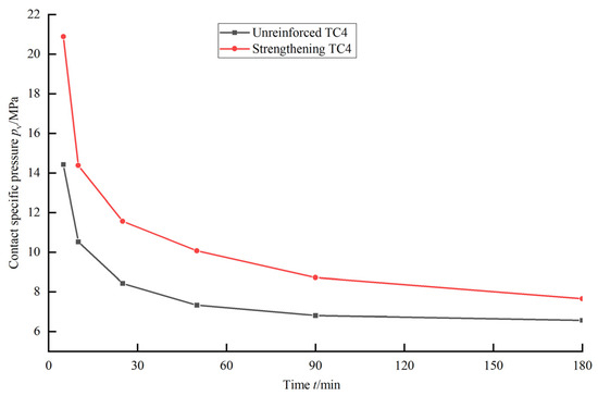
Figure 19.
Curve of contact specific pressure of ring pin with time.
The comparison of specimen wear loss after the test is presented in Figure 20. Analysis results show that the wear loss of strengthened TC4 is 56.5 mg, which is a significant reduction of approximately 32.81% compared with unreinforced TC4 wear loss of 84.1 mg. Furthermore, the wear loss of CFRPEEK mated with unreinforced TC4 is 592.1 mg, whereas that mated with strengthened TC4 is 492.7 mg. These results confirm a significant reduction in wear loss for TC4 mating pairs subjected to ultrasonic rolling extrusion strengthening. It is indicated thereby that not only are the tribological properties of TC4 improved by the ultrasonic rolling extrusion strengthening process, but the consumption of the mated CFRPEEK is also reduced, which bears positive significance for the design of water-lubricated friction pairs.
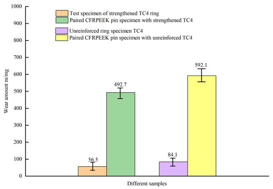
Figure 20.
Wear amount of ring pin sample.
4.3. Analysis of Friction and Wear Mechanism
In addition to evaluating the friction and wear properties of TC4 modified by ultrasonic rolling extrusion using friction coefficient and wear loss, the friction and wear mechanism can also be analyzed by observing the microtopography of TC4 and CFRPEEK mating pairs via scanning electron microscopy (SEM). The TC4 specimens (both before and after strengthening) and their corresponding CFRPEEK mating pairs that had undergone the friction and wear test were ultrasonically cleaned to remove residual impurities on their surfaces. Subsequently, these specimens were placed in an SEM, and their microtopography was observed.
The wear morphology of unreinforced TC4 after friction and wear testing is presented in Figure 21. As observed from the figure, multiple wear characteristics including fatigue wear, scratches, plowing grooves, indentations, and material transfer adhesion are exhibited on the TC4 surface. Since the hardness of carbon fibers (CFs) in CFRPEEK (>3000 HV) is much higher than that of unreinforced TC4, the CFs exposed after the wear of the PEEK matrix repeatedly abrade the TC4 surface under the action of high contact pressure, leading to plastic deformation and fatigue wear on the TC4 surface. With the detachment of metal particles, the formed wear debris further generates plowing grooves and scratches during relative movement, and severe abrasive wear is ultimately induced. In addition, under the combined effects of PEEK matrix wear and mechanical friction, short-cut CFs are peeled off from the matrix and pressed into the TC4 surface under the action of applied load, resulting in the formation of plastic deformation and pit indentations. Meanwhile, because the PEEK matrix hardness is significantly lower than that of TC4, part of the PEEK material adheres to the rough metal surface. To summarize, the main wear mechanisms of unreinforced TC4 are identified as fatigue wear and abrasive wear.
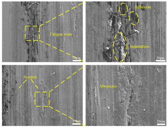
Figure 21.
Wear morphology of local area of unreinforced TC4.
The wear morphology of strengthened TC4 is shown in Figure 22. Compared with unreinforced TC4, the surface of strengthened TC4 is much smoother, with shallower wear scars and significantly reduced adherents, indicating that its wear resistance has been significantly improved. As can be observed from the figure, PEEK matrix material is embedded along the sliding friction direction. This is because under high contact pressure, the low-hardness PEEK matrix undergoes shear detachment during friction and is transferred to the titanium alloy surface. It is noteworthy that no plastic deformation or fatigue wear phenomena are observed on the surface of strengthened specimens. This is mainly attributed to the residual compressive stress formed in the material surface layer by ultrasonic rolling extrusion strengthening treatment, which effectively enhances the fatigue resistance of the material. Since hardness is a key parameter for abrasive wear resistance, the surface hardness of strengthened TC4 is significantly increased, and the ability to resist abrasive wear is correspondingly improved. In summary, the main wear mechanism of strengthened TC4 is identified as mild abrasive wear.
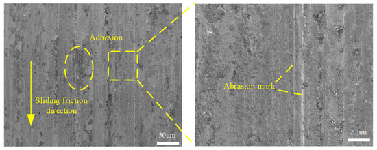
Figure 22.
Wear morphology of strengthened TC4.
Figure 23 shows the surface morphology of CFRPEEK before wear testing. The wear morphology of CFRPEEK mated with unreinforced TC4 is shown in Figure 24. Obvious wear scars are observed along the sliding friction direction. The formation mechanism of these scars may be attributed to the action of residual wear debris on the surface of the mated unreinforced TC4, causing severe low-stress abrasive wear to be induced on CFRPEEK. The adherents observed on the sliding surface of unreinforced TC4 confirm that adhesive wear is also exhibited by CFRPEEK. Therefore, under the working condition of sliding against unreinforced TC4, the wear mechanism of CFRPEEK is dominated by abrasive wear, with a certain degree of adhesive wear accompanied.
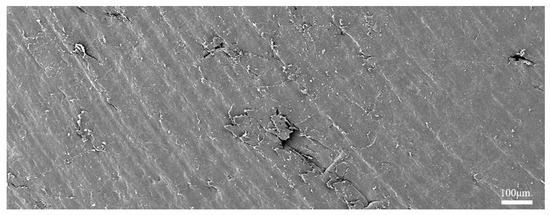
Figure 23.
Surface morphology of CFRPEEK before wear testing.
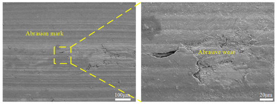
Figure 24.
Wear morphology of CFRPEEK worn against unreinforced TC4.
The wear morphology of CFRPEEK slid against strengthened TC4 is presented in Figure 25. As observed from the figure, slight friction marks and PEEK matrix peeling are present along the sliding direction. The reduction in friction marks is mainly attributed to the lower surface roughness and higher hardness of strengthened TC4, which significantly weakens the low-stress abrasive wear effect. However, during the long-duration friction test, repeated extrusion induces fatigue on the CFRPEEK surface, leading to peeling and scaling phenomena. Meanwhile, the combined action of repeated extrusion and rotational entrainment further promotes such peeling and scaling. In summary, the main wear mechanisms of the strengthened TC4-CFRPEEK friction pair are identified as mild abrasive wear and fatigue wear.
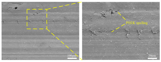
Figure 25.
Wear morphology of CFRPEEK worn against strengthened TC4.
The tribological behavior of the TC4-CFRPEEK friction pair is fundamentally governed by the synergistic interactions at the atomic scale, encompassing interfacial chemical bonding, microstructural evolution, and energy transfer. According to molecular dynamics (MD) [31,32] and density functional theory (DFT) simulations [33,34], weak chemisorption bonds—primarily Ti–O bonds—are formed through electron cloud overlap between polar groups (e.g., –O–, –COOH) in CFRPEEK molecular chains and Ti atoms on the TC4 surface, which constitutes the principal origin of interfacial adhesive resistance. Concurrently, the pronounced lattice mismatch between the hexagonal close-packed (HCP) structure of TC4 and the amorphous matrix of CFRPEEK, along with the hexagonal lattice of carbon fibers, substantially lowers the energy barrier for atomic sliding at the interface. As a result, shear deformation is preferentially accommodated at the heterogeneous interface rather than within the bulk materials, thereby establishing an atomic-scale foundation for the macroscopically low friction coefficient of the friction pair.
During the wear process, atomic-scale plastic deformation dominated by dislocation nucleation and slip is experienced in the TC4 surface layer, while nanoscale wear debris is generated in CFRPEEK through molecular chain fracture and dynamic reorganization. The cooperative action of these mechanisms effectively inhibits large-scale material spalling. Under seawater lubrication, direct atomic interactions are weakened by competitive adsorption of ions such as Cl− and Na+ at the interface, and the resulting dense hydration film further reduces the interfacial shear strength, thereby modulating the wear behavior. Through ultrasonic rolling extrusion strengthening, gradient nanostructures and residual compressive stress fields are introduced into the TC4 surface layer, leading to the optimization of electron cloud density, interatomic spacing, and slip resistance of Ti atoms. This results in an interfacial synergistic strengthening effect with CFRPEEK, ultimately achieving a significant enhancement in the overall wear resistance of the friction pair.
5. Conclusions
To improve the wear resistance of TC4 with excellent corrosion resistance, the influence of ultrasonic rolling process parameters on the surface performance of TC4 was investigated by means of finite element simulation and experiment. The wear resistance and friction reduction effect of ultrasonic rolling strengthening on TC4 under seawater lubrication was studied via wear test. The main research contents and conclusions are as follows:
- (1)
- In the ultrasonic rolling extrusion simulation process, the residual stress on the TC4 surface is increased with the increase in static pressure and amplitude, while decreased with the increase in rotational speed. It reaches a critical value when the static pressure is 600 N, and the amplitude is 10 μm. The residual stress on the surface does not change significantly with the rotational speed, with the maximum variation amplitude being less than 8%. The surface roughness of the TC4 rolled area is shown to first decrease and then increase with the increase in static pressure, amplitude, and rotational speed. Optimal surface performance of TC4 is achieved within the following parameter ranges: static pressure of 0–600 N, amplitude of 5–10 μm, and rotational speed of 0–600 r/min.
- (2)
- Process parameters including static pressure, amplitude, rotational speed, and rolling times exert a significant influence on the surface performance of components treated by ultrasonic rolling extrusion. After optimizing the process parameters, the surface performance of TC4 under the optimal parameter combination was verified experimentally. Experimental results indicate that the experimental values are highly consistent with the predicted values from the prediction model, with the maximum relative errors of predicted surface hardness and roughness under the optimal parameter combination controlled within 5%. The microstructure of TC4 after ultrasonic treatment exhibits a gradient distribution feature, from the surface layer to the core, a severely plastically deformed layer (with a depth of approximately 45 μm), and a transition layer (in the range of 45–110 μm), and the TC4 matrix are sequentially observed.
- (3)
- In the friction and wear tests under seawater lubrication, the friction coefficients of strengthened and unreinforced TC4 are measured as 0.05739 and 0.07891, respectively. Compared with unreinforced TC4, a reduction of 27.27% in friction coefficient and 32.81% in wear rate is achieved for strengthened TC4; meanwhile, a significant decrease in the wear loss of the mated CFRPEEK is also observed. The resistance of TC4 to fatigue wear and abrasive wear is significantly enhanced by ultrasonic rolling extrusion treatment, and its wear mechanism is identified as mainly mild abrasive wear. The wear mechanism of the mated CFRPEEK is transformed from severe abrasive wear and adhesive wear to mild abrasive wear and fatigue wear.
Author Contributions
Methodology, D.L.; Validation, X.M., Y.T., F.Z., Y.L. and X.W.; Writing—Original Draft, S.W.; Writing—Review and Editing, S.W. All authors have read and agreed to the published version of the manuscript.
Funding
This research was funded by the National Key Research and Development Program of China (Grant No. 2022YFC2805702), the National Natural Science Foundation of China (Grant Nos. 52475053 and 52105054), and the Zhong yuan Science and Technology Innovation Youth Top Talent Project (Grant No. ZYQNBJRC2025-03).
Data Availability Statement
The data-supported results are included within this article.
Conflicts of Interest
Authors Xianshuai Ma, Yong Tang, Feng Zhao were employed by Xinxiang Aviation Industry Group Co., Ltd. The remaining authors declare that the research was conducted in the absence of any commercial or financial relationships that could be construed as a potential conflict of interest.
References
- Liu, Y.; Cheng, Q.; Wang, Z.; Pang, H.; Deng, Y.; Zhou, X.; Wu, D. Seawater Hydraulics: From the Sea Surface to Depths of 11000 Meters. Sci. China Technol. Sci. 2022, 65, 2178–2189. [Google Scholar] [CrossRef]
- Haugan, P.M.; Levin, L.A.; Amon, D.; Hemer, M.; Lily, H.; Nielsen, F.G. What Role for Ocean-Based Renewable Energy and Deep-Seabed Minerals in a Sustainable Future? In The Blue Compendium: From Knowledge to Action for a Sustainable Ocean Economy; Springer: Cham, Switzerland, 2023; pp. 51–89. [Google Scholar] [CrossRef]
- Nie, S.; Guo, M.; Yin, F.; Ji, H.; Ma, Z.; Hu, Z.; Zhou, X. Research on Fluid-Structure Interaction for Piston/Cylinder Tribopair of Seawater Hydraulic Axial Piston Pump in Deep-Sea Environment. Ocean Eng. 2021, 219, 108222. [Google Scholar] [CrossRef]
- Pawlus, W.; Choux, M.; Hansen, M. Hydraulic vs. Electric: A Review of Actuation Systems in Offshore Drilling Equipment. Model. Identif. Control 2016, 37, 1–17. [Google Scholar] [CrossRef]
- Cui, Y.; Ma, Q.; Wu, Z.; Lu, H.; Gao, Z.; Fan, J. A Hydrostatic Pressure-Driven Desalination System for Large-Scale Deep Sea Space Station. Int. J. Chem. Eng. 2021, 2021, 8898472. [Google Scholar] [CrossRef]
- Dai, C.H.; Lao, X.S.; Liu, Y.; Wei, W. Experimental Study on Water-Lubricated Bearing Material in Deep Sea Space Station. Mater. Sci. Forum 2019, 947, 155–159. [Google Scholar] [CrossRef]
- Wei, H.B.; Su, W.B.; Gao, X.Q. Design and Experimentation of Hydraulic Turbine for Low-Flow Ocean Current Energy Transmission and Control Power Generation Equipment. In Proceedings of the 2022 5th International Conference on Energy, Electrical and Power Engineering (CEEPE), Chongqing, China, 22–24 April 2022; IEEE: New York, NY, USA; pp. 938–943. [Google Scholar] [CrossRef]
- Li, D.; Ma, X.; Wang, S.; Lu, Y.; Liu, Y. Failure Analysis on the Loose Closure of the Slipper Ball-Socket Pair in a Water Hydraulic Axial Piston Pump. Eng. Fail. Anal. 2024, 155, 107718. [Google Scholar] [CrossRef]
- Yin, F.; Zhou, X.; Nie, S.; Ji, H.; Hu, Z. Tribocorrosion Behavior of Several Corrosion-Resistant Alloys Sliding against CF-PEEK: Application for Hydraulic Valve in Seawater. Int. J. Electrochem. Sci. 2019, 14, 4643–4658. [Google Scholar] [CrossRef]
- Liang, Y.; Zhang, Z.; Liu, X.; Shen, M.; Wang, W.; Xing, H.; Wang, C.; Gao, D. Experimental Study on Tribological Properties of Coated Surface and Textured Surface under Seawater Lubrication Conditions. Coatings 2024, 14, 415. [Google Scholar] [CrossRef]
- Ma, K.; Wu, D.; Xu, R.; Pang, H.; Liu, Y. Experimental Investigation and Theoretical Evaluation on the Leakage Mechanisms of Seawater Hydraulic Axial Piston Pump under Sea Depth Circumstance. Eng. Fail. Anal. 2022, 142, 106848. [Google Scholar] [CrossRef]
- Li, D.; Ma, X.; Wang, S.; Wang, J.; Yang, F.; Liu, Y. The difference in tribological characteristics between CFRPEEK and stainless steel under water lubrication in friction testing machine and axial piston pump. Lubricants 2023, 11, 158. [Google Scholar] [CrossRef]
- Feng, S.; Zhou, Z.H.; Yang, L.L.; Qiao, Y.X.; Wang, J.L.; Wang, F.H. Electrochemical and Wear Behavior of TC4 Alloy in Marine Environment. J. Chin. Soc. Corros. Prot. 2024, 44, 1243–1254. [Google Scholar] [CrossRef]
- Yin, F.L.; Kong, X.L.; Ji, H. Research on the Pressure and Flow Characteristics of Seawater Axial Piston Pump Considering Cavitation for Reverse Osmosis Desalination System. Desalination 2022, 540, 18. [Google Scholar] [CrossRef]
- Yang, J.; Liu, D.; Ren, Z.; Zhi, Y.; Zhang, X.; Zhao, R.; Liu, D.; Xu, X.; Fan, K.; Liu, C. Grain growth and fatigue behaviors of GH4169 superalloy subjected to excessive ultrasonic surface rolling process. Mater. Sci. Eng. A 2022, 839, 142875. [Google Scholar] [CrossRef]
- Wang, S.; Liu, S.; Li, Y.; Yu, T.; Liu, X.; Du, N. Effect of Corrosion on the Fatigue Damage Behavior of M50 Steel Treated by Ultrasonic Surface Rolling Process. J. Mater. Res. Technol. 2024, 31, 351–362. [Google Scholar] [CrossRef]
- Huang, P.; Wang, Y.; Lin, J.; Cheng, Y.; Liu, F.; Qiu, Q. Effect of Ultrasonic Rolling on Surface Integrity, Machining Accuracy, and Tribological Performance of Bearing Steels under Different Process Schemes. CIRP J. Manuf. Sci. Technol. 2023, 43, 143–157. [Google Scholar] [CrossRef]
- Ren, K.; Xue, J.; Tang, C.; Su, L.; Bi, Q.; Tian, Y. Improved Interfacial Adhesion of Ni/Epoxy Coatings on Steel Substrate by Ultrasonic Surface Rolling Process. J. Alloys Compd. 2025, 1017, 179167. [Google Scholar] [CrossRef]
- John, M.; Ralls, A.M.; Dooley, S.C.; Thazhathidathil, A.K.V.; Perka, A.K.; Kuruveri, U.B.; Menezes, P.L. Ultrasonic Surface Rolling Process: Properties, Characterization, and Applications. Appl. Sci. 2021, 11, 10986. [Google Scholar] [CrossRef]
- Zhang, K.M.; Liu, S.; Wang, J.; Sun, Z.X.; Liu, W.J.; Zhang, C.C.; Zhang, X.C. Effect of High-Frequency Dynamic Characteristics in the Ultrasonic Surface Rolling Process on the Surface Properties. J. Mater. Process. Technol. 2024, 327, 118353. [Google Scholar] [CrossRef]
- Liu, G.; Su, Y.G.; Pi, X.Y.; Wen, D.X.; Liu, D.F.; Lin, Y.C. Enhanced Electrochemical Corrosion Resistance of 316L Stainless Steel Manufactured by Ultrasonic Rolling Assisted Laser Directed Energy Deposition. China Foundry 2025, 22, 182–194. [Google Scholar] [CrossRef]
- Wang, X.; Wang, H.; Wang, P.; Zhu, Q. Multi-Objective Optimization of Process Parameters for Ultrasonic Rolling Extrusion of 42CrMo Material. Mech. Ind. 2023, 24, 6. [Google Scholar] [CrossRef]
- Wang, H.; Wang, X.; Tian, Y.; Ling, Y. Simulation Study of Turning-Ultrasonic Rolling Compound Processing for 42CrMo Steel. Sci. Rep. 2024, 14, 23088. [Google Scholar] [CrossRef]
- Wang, H.; Wang, X.; Tian, Y.; Ling, Y. Study on Theory and Finite Element Simulation of Ultrasonic Rolling Extrusion Process. Int. J. Adv. Manuf. Technol. 2024, 134, 1091–1109. [Google Scholar] [CrossRef]
- Yin, W.; Liu, Y.; He, X.; Tian, Z. Parametric Analysis and Improvement of the Johnson-Cook Model for a TC4 Titanium Alloy. Metals 2024, 14, 1199. [Google Scholar] [CrossRef]
- De Oliveira, L.G.; de Paiva, A.P.; Balestrassi, P.P.; Ferreira, J.R.; da Costa, S.C.; da Silva Campos, P.H. Response Surface Methodology for Advanced Manufacturing Technology Optimization: Theoretical Fundamentals, Practical Guidelines, and Survey Literature Review. Int. J. Adv. Manuf. Technol. 2019, 104, 1785–1837. [Google Scholar] [CrossRef]
- Peng, F.; Guo, C.; Jiang, F.; Yuan, D.; Yin, H.; Sun, Q.; Zhang, H.; Dong, T.; Guo, D.; Konovalov, S. Microstructure evolution and mechanical properties of Ti-6Al-4V alloy fabricated by directed energy deposition assisted with dual ultrasonic vibration. Mater. Sci. Eng. A 2025, 925, 147934. [Google Scholar] [CrossRef]
- Ao, N.; Liu, D.; Zhang, X.; Liu, C.; Yang, J.; Liu, D. Surface nanocrystallization of body-centered cubic beta phase in Ti–6Al–4V alloy subjected to ultrasonic surface rolling process. Surf. Coat. Technol. 2019, 361, 35–41. [Google Scholar] [CrossRef]
- Ao, N.; Liu, D.; Xu, X.; Zhang, X.; Liu, D. Gradient nanostructure evolution and phase transformation of α phase in Ti-6Al-4V alloy induced by ultrasonic surface rolling process. Mater. Sci. Eng. A 2019, 742, 820–834. [Google Scholar] [CrossRef]
- Panin, A.V.; Kazachenok, M.S.; Dmitriev, A.I.; Nikonov, A.Y.; Perevalova, O.B.; Kazantseva, L.A.; Sinyakova, E.A.; Martynov, S.A. The effect of ultrasonic impact treatment on deformation and fracture of electron beam additive manufactured Ti-6Al-4V under uniaxial tension. Mater. Sci. Eng. A 2022, 832, 142458. [Google Scholar] [CrossRef]
- Zhao, X.; Tang, Y.; Chen, K.; Cai, Y.; Liang, X.; Liu, Z.; Li, D. Bauschinger effect in nano-grinding of 3C-SiC: A molecular dynamics study. Wear 2025, 571, 205847. [Google Scholar] [CrossRef]
- Jiang, T.; Tang, J.; Zhao, J.; Ling, Y.; Zeng, Y. Insight into the nanoscale strengthening mechanism of polycrystalline iron implanted by Cr ions. Mater. Des. 2025, 253, 113814. [Google Scholar] [CrossRef]
- Diao, G.; Tang, Y.; He, A.; Wu, M.; Zhang, D.; Fraser, D.; Li, J.; Chung, R.; Li, D. Tune Al/Ti to adjust FCC+L21 hetero-structured Ni-based high-entropy alloys for improved mechanical properties and wear resistance. Acta Mater. 2024, 281, 120399. [Google Scholar] [CrossRef]
- Dong, H.; Chen, Y.; Wu, D.; Ma, H.; Feng, Z.; Su, R. Unlocking the potential of trace cobalt in Ni-based superalloys: A molecular dynamics study on dislocation behavior and high-temperature stability. Mater. Des. 2025, 253, 113905. [Google Scholar] [CrossRef]


Disclaimer/Publisher’s Note: The statements, opinions and data contained in all publications are solely those of the individual author(s) and contributor(s) and not of MDPI and/or the editor(s). MDPI and/or the editor(s) disclaim responsibility for any injury to people or property resulting from any ideas, methods, instructions or products referred to in the content. |
© 2025 by the authors. Licensee MDPI, Basel, Switzerland. This article is an open access article distributed under the terms and conditions of the Creative Commons Attribution (CC BY) license.