Abstract
The majority of bearings in the world are lubricated by grease, and nearly 80% of premature bearing damage is attributed to lubrication issues. Accurate measurement and prediction of film thickness are crucial aspects of understanding the lubrication mechanism in grease-lubricated bearings. This work focuses on grease film thickness measurement using the capacitance method in real bearings. It comprehensively reviews the current status, identifies key challenges, and proposes solutions. Mechanisms of mainstream electronic components in capacitance measurement were reviewed for the first time. It enables more accurate capacitance measurement. A new capacitive model and electric network to measure film thickness in fully flooded, starved, and mixed regimes are developed. It is more comprehensive compared to current models. Classic dielectric models are reviewed, and suitable ones for lubricants are proposed. It facilitates a more precise film thickness measurement. Finally, a new grease film thickness model (bearing raceway) is proposed based on the 113 literature capacitive film thickness data points from five different authors. The satisfied R-squared value indicates a strong correlation.
1. Introduction
The film thickness of lubricants plays a vital role in predicting the performance and life of rolling element bearings. For oil-circulated bearings, where a fully flooded condition is typically assumed, the two surfaces are completely separated, and the film thickness is not affected by a change in oil flow at the inlet. This allows for relatively accurate predictions using the classic Hamrock and Dowson film thickness equation [1]. Grease, however, presents a great challenge. Unlike oil, grease-lubricated bearings are usually considered to operate under starved lubrication or “starvation” conditions.
While the rolling surfaces remain separated, the film thickness is highly dependent on the lubricant supply at the inlet. The physics and chemistry of lubricating grease in a rolling bearing are not well understood [2]. Poll et al. reviewed the generation mechanism and criteria of starvation in rolling contacts [3]. Although significant efforts have been conducted, a reliable model to predict the grease film thickness in rolling element bearings has yet to be developed.
Accurate measurement of lubricant film thickness is crucial for model development and verification. Albahrani et al. comprehensively reviewed in situ film thickness measurement methods in the elastohydrodynamic lubrication (EHL) regime [4]. These methods fall into three categories reflective of their fundamental principles: electrical methods (voltage discharge, resistance, capacitance); optical methods (X-ray, interferometry, infrared, Raman, fluorescence, particle image velocimetry); and acoustic methods. Liu et al. compared the EHL experimental techniques with numerical methods and found good agreement in most cases [5].
For grease film thickness measurement specifically, optical interferometry [6,7,8,9], X-ray [10], ultrasonic [11], resistance [12,13,14,15], and capacitance methods [16,17,18,19,20,21,22] have been explored. Optical interferometry provides high resolution for film thickness measurement. However, it cannot mimic the starved lubrication condition in a rolling element bearing. Most optical measurements of grease were conducted in fully flooded conditions using a scoop. X-ray, ultrasonic, and resistance methods are limited in resolution, typically only reaching the micrometer level, whereas grease film thickness falls into the nanometer range in starved conditions. Consequently, the capacitance method has emerged as the most suitable tool for in situ film thickness measurement in grease-lubricated bearings. It exhibits comparable resolution with optical interferometry [23] and can be applied to real bearings without complicated modifications. The characteristics of each method are summarized in Table 1.
The capacitance method was invented by Crook in 1958 [24]. The evolution of this method has been reviewed by Cen et al. [25] and Glovnea et al. [26] and will not be elaborated here. Beyond film thickness measurement, capacitance has been applied widely, such as in lubricant degradation monitoring [27,28,29,30,31,32,33,34,35,36,37,38] and metallic surface contact detection [39,40,41,42,43,44,45,46,47].
The capacitance method applied to film thickness measurement has been reviewed in terms of lubricant type, rig configuration, central film thickness range, and lubrication regimes (summarized in Table 2). The majority of the research to date has focused on oil lubrication in the fully flooded conditions. However, several critical knowledge gaps remain:
- Capacitance measurement methods: Currently, no commercial bearing testing rig is available. Several homemade rigs were recently reported to measure bearing capacitance [17,23,48,49,50,51]. A deeper understanding of the physics behind capacitance measurement methods is important for future capacitance testing rig design and optimization;
- Capacitive film thickness models and electric networks: Current models primarily focus on the film thickness in fully flooded conditions. A more comprehensive model encompassing all three lubrication regimes (fully flooded, starved, and mixed) is necessary to reflect bearing operation in the real world;
- Dielectric constant of lubricants: Accurate film thickness determination relies heavily on the lubricant’s dielectric constant, which is a function of temperature and pressure (among other parameters). A suitable model for grease is needed;
- Grease starvation: It is necessary to develop a grease starvation model based on current capacitive film thickness data.
This review aims to bridge these knowledge gaps in the field of grease-lubricated bearings and pave the way for future advancements.

Table 1.
Characteristics of different grease film thickness measurement methods.
Table 1.
Characteristics of different grease film thickness measurement methods.
| Elementary Particle/Fundamental Carriers | Method | High-Spatial Resolution (~nm) | Real-Bearing Test | In Situ Measurement |
|---|---|---|---|---|
| Electron | Capacitance | √ | √ | √ |
| Resistance | √ | √ | ||
| Photon | Optical | √ | √ | |
| X-ray | √ | |||
| Phonon | Ultrasonic | √ | √ |
Table 2.
Summary of lubricant film thickness measurement using capacitance methods.
Table 2.
Summary of lubricant film thickness measurement using capacitance methods.
| Lubricants | Rig Configuration | Capacitance Measurement | Central Film Thickness Range (µm) | Lubrication Regime | Research Area | Reference |
|---|---|---|---|---|---|---|
| Oil and grease | Twin-disk rig and ball bearing test rig | Measure the capacitor voltage change during charging | 0.2~1.2 | Fully flooded and starved | Bearing currents and electrical erosive wear study | [16] |
| Grease | Deep-groove ball bearing and optical rig (WAM5) | Lubcheck + oscilloscope | 0~0.2 | Fully flooded and starved | Difference in the lubrication mechanism between ultra-low speed and medium speeds | [18] |
| Oil and grease | Deep-groove ball bearing | Capacitive voltage divider (Lubcheck) | 0.04~0.2 | Mix to fully flooded | Film thickness and condition monitoring (metallic contact time fraction) | [49] |
| Grease | Deep-groove ball bearing | Lubcheck Mk3 | 0.5~3 | Starved | Grease starvation quantification | [50] |
| Grease | Angular contact ball bearing | Constant–current charge | 0~0.7 | Starved | Influence of lubricating grease composition on grease service life and tribological performance characteristics in high-speed rolling bearings | [48] |
| Oil | FEA simulation on a ball bearing | 10~1000 | Fully flooded | Analyze bearing current discharges and their effect on bearing damage by using simulation | [52] | |
| Gear oil | Pair of gears | RLC bridge and oscilloscope | 5~140 | Fully flooded | Studied the effect of change in speed, oil viscosity, and helix angle on the load-carrying capacity of the oil film | [53] |
| SAE 30, 60 | Engine crankshaft journal and bearing shell | Transformer ratio arm bridge | 0.65~8 | Fully flooded | Measured the relative effects of oil rheology and engine operating condition | [54] |
| Grease | Deep-groove ball bearing | Lubcheck Mk3 | Starved | Grease replenishment study | [55] | |
| Mineral oil | Twin-disk machine | Capacitance bridge | 0.5 | Fully flooded | In general terms, it appears the elasto-hydrodynamic theory may have slightly underestimated the film thicknesses | [56] |
| Oil | Engine connecting–rod bearing | Capacitance bridge | 0~10 | Fully flooded | Thermal effects on oil film thickness of an engine connecting–rod bearing | [57] |
| Sunflower oil | Ball-on-disk tribometer | LCR meter | 0.001~0.01 | Boundary | Measured the thickness of boundary films under a pure sliding contact between metallic surfaces | [58] |
| Air/oil | Online transportation tube | Electrical capacitance tomography sensor | 60~140 | Air/oil transportation | Monitoring of the in-tube air/oil flow | [59] |
| Oil | Single-cylinder diesel engine | Capacitance probe | 0.2~8 | Fully flooded | Oil film thickness between engine cylinder liner and piston ring | [60] |
| Oil | Motored engine | Capacitance probe | 0~4 | Fully flooded | Oil film thickness between engine cylinder liner and piston ring | [61] |
| Oil | Internal combustion engine | Capacitance transducers | 0~80 | Fully flooded and starved | Measured capacitance between the sensor and piston ring | [62] |
| Grease | Angular contact ball bearings | Relative film thickness | Starved | Combined grease life testing with film thickness measurement | [63] | |
| Grease | Radial ball bearings | High-frequency oscilloscope | Starved | Bearing film thickness measurement | [64,65] | |
| Oil | Single-cylinder diesel engine | Capacitance transducer | 6~18 | Cavitation | Film between piston ring and liner | [66] |
| Oil | Diesel engine | Capacitance transducer | 2~8 | Fully flooded | Film between piston ring and cylinder | [67] |
| Oil | Modified MTM test rig | Digital storage oscilloscope with large memory | 0.05~0.9 | Fully flooded | Electric discharge behavior and current damage in EV motor bearings | [68] |
| Oil | Four-disk machine | Capacitance gauge | 4~26 | Fully flooded | Measured film shape, pressure, and temperature profiles | [69] |
| Oil | Diesel engine | Capacitance gauge | 0.4~2.5 | Fully flooded | Piston rings and the cylinder liner | [70] |
| Oil | Diesel engine | Capacitance gauge | 1~11 | Fully flooded | Piston rings and the cylinder liner | [71] |
| Oil | Two-spherical ball contact | LCR meter | 0~2.5 | Fully flooded | Measured the film thickness from pure rolling to pure sliding | [72] |
| Oil | Thrust pad bearing | Capacitance probes | 2.5~25 | Fully flooded | Compared the deflection of a circular pad with theory | [73] |
| Oil | Twin disk | LC oscillator | 0.2~1.8 | Fully flooded | Prediction of lubrication film thickness under conditions of different surface velocity directions | [74] |
| Oil | Bearing in a diesel engine | Transducer | 10~60 | Fully flooded | Measured the hydrodynamic oil film thickness present in slide bearings | [75] |
| Oil | EHD rig | Impedance/gain-phase analyzer | 0.015~0.2 | Fully flooded | Quantitative measurements of film thickness and consideration of cavitation | [76] |
| Oil with different polarity | EHD rig | Impedance analyzer | 0.01 | Fully flooded | Influence of a lubricant’s polarity on capacitance measurements | [77] |
2. Capacitance Measurement Methods
This section focuses on the mechanisms of various capacitance measurement methods, including oscilloscope, AC bridge, LCR meter, impedance analyzer, voltage divider, and capacitance probe/transducer.
Capacitance, C is defined as the ability of a system to store an electric charge. It is the ratio of the change in charge, Q and the corresponding change in the electric potential V.
Grease film thickness in the starved condition is relatively stable (assuming no degradation, evaporation, or leakage), and the capacitance does not change with time, so (2) can be reduced to
2.1. Oscilloscope
Numerous instruments can measure voltage and current. An oscilloscope is the most versatile one. It allows the user to record the circuits’ voltage over time [78]. The capacitance can then be computed for a known current as follows:
When subject to a constant current, capacitance is inversely proportional to the slope of the voltage–time curve. This is also called a “constant current charging-up method”, which was applied by Franke and Poll [48].
2.2. AC Bridge
Wilson used a capacitance bridge to measure the film thickness in a grease-lubricated bearing [20]. The alternating current bridge is one of the most widely used methods of measuring circuit constants at audio frequencies, as shown in Figure 1. When such a bridge is balanced, and no current flows through the null detector located in the center, then
where Z is the impedance of each electric component.
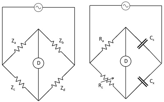
Figure 1.
An alternating current bridge and a simple capacitance bridge.
For a simple capacitance bridge, is a standard capacitor, and is an unknown capacitor. and are standard resistors. is adjustable. When the bridge is balanced,
In AC circuits, impedance Z is a combination of resistance R and reactance X.
Reactance X represents the opposition due to the reactive components in the circuit. Inductive reactance opposes changes in current due to the magnetic field generated by the inductors, which is always positive. Capacitive reactance opposes changes in voltage due to the electric field stored by the capacitors, which is always negative. When a capacitor and an inductor are connected in series,
where is the AC signal frequency; is the angular frequency; is the inductance, and is the capacitance.
2.3. LCR Meter and Impedance Analyzer
For an LCR meter, stands for capacitor, and stands for resistor. stands for inductor. It is closely related to the capacitor. The rate of current change in an inductor is proportional to the voltage applied across it:
An LCR meter measures the capacitance by determining the capacitive reactance at a specific frequency. When an AC signal is applied to the capacitor, the LCR meter measures the impedance , which is composed of resistance (real part) and capacitive reactance (imaginary part). The imaginary unit, or factor, accounts for the 90° leading phase shift of current versus voltage [78].
where is the measured phase angle between the voltage and current.
The capacitive reactance is given by
For a parallel plate capacitor, the capacitance is calculated as
The contact resistance is calculated as
Some types of LCR meters can only measure the basic parameters of passive components: inductance (L); capacitance (C); and resistance (R). However, an impedance analyzer is able to measure the complete impedance, including both magnitude and phase angle. It provides a comprehensive picture of the electrical behavior across a wide frequency range. It is used for broad-spectrum characterization. An impedance analyzer has been reported for bearing capacitance measurement [17]. A low-voltage (50 mV) and high-frequency (100 kHz) current source was set to avoid grease film breakdown during starvation.
2.4. Capacitive Voltage Divider
Figure 2 shows a simple capacitive voltage divider. is the voltage input, and is the voltage measured on the unknown capacitor . is a standard capacitor. Since the two capacitors are connected in series,
The SKF Lubcheck method is based on a capacitive voltage divider [51]. The following relationship was reported, which is the same as (29).
where is bearing electrical capacitance; is output voltage, and is reference capacitance.

Figure 2.
A simple capacitive voltage divider.
2.5. Capacitance Probe/Transducer
The capacitance probe is a well-established technique for measuring oil film thickness in internal combustion (IC) engines [54,60,61,70,79]. It can be used to measure the film between the piston ring and cylinder liner, as well as the film between the crankshaft journal and the bearing shell [79]. In the ring and liner scenario, the capacitor forms between the electrode inside the probe and the piston ring. However, probes are not particularly suitable for making direct measurements of oil film thickness when it is less than 5 µm [70].
2.6. Summary
The oscilloscope, AC bridge, LCR meter, impedance analyzer and voltage divider are able to measure thin film with high resolution. From the measurement range perspective, the LCR meter and impedance analyzer seem more suitable for analyzing complex electrical behavior.
3. Capacitive Film Thickness Models and Electric Networks
Several test rig configurations have been employed for film thickness measurement using the capacitance method. These studies have described the geometry and electrical network models of the rigs, from benchmark testing rigs (twin disks [16,19,24,56,63,69,80,81] and pin-on disk [41,76]) to full-bearing rigs (ball-bearing [22,23,43,51,82,83,84,85,86] and roller-bearing [20,87]). While the majority of research focuses on fully flooded lubrication conditions, some studies have explored mixed mode [23,40,41], starved lubrication [51], and parched EHL [46,47,88]. Details are summarized in Table 3.
Table 3.
Summary of geometric models and electric networks to convert capacitance to film thickness.
A new film thickness measurement model that covers all three lubrication regimes (fully flooded, starvation, and mixed) is proposed here. The model is based on the following assumptions (not limited to):
- The capacitance of the film thickness can be modeled as a parallel plate capacitor;
- Film in the contact region is composed of oil without any thickener;
- A deep-groove ball bearing under axial load is used so the load on each ball is considered equally distributed;
- A polymer cage is used to simplify the electronic network;
- The effect of surface asperities on resistance measurement is neglected;
- The temperature gradient through the inlet, contact, and outlet regions is neglected.
3.1. Fully Flooded
The total measured capacitance is the sum of bearing capacitance , and background capacitance is calculated as follows:
Background capacitance can be measured with a ceramic ball bearing with the same geometry. In engineering practices, any two conductors in close proximity may act as a capacitor, such as the interference between adjacent circuits. In addition, some unwanted electrical signals may be induced by background capacitance due to a high-frequency alternating source. Assuming inner and outer-race capacitance is connected in series, and the capacitances of the different balls are connected in parallel:
where is the number of balls.
The relationship between the inner and outer-race films was calculated based on the contact geometry and temperature difference [51]:
It is also assumed that this relationship works for both fully flooded and starved conditions [51].
The following discussion focuses on the inner raceway contact only. There are five regions: inlet; Hertzian contact; outlet; and two side-leakage areas [22]. Due to the small area of side leakage, those regions are neglected by the majority of the literature [16,19,22,23,40,41,43,51,63,69,76,81,82,83,84,85,86,87]. This simplification has also been adopted in the present research.
The electric network is shown in Figure 3. The inlet, contact (Hertzian), and outlet (cavitation) regions are connected in parallel:
where is the central film thickness in the contact region.
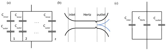
Figure 3.
Electronic network of the bearing (a) and a single-raceway contact (b,c).
For the inlet region as shown in Figure 4, is assumed to be equal to the dielectric constant of oil under ambient pressure. The inlet section is assumed to be full of oil under a fully flooded condition, the same as Crook [24,92]. The geometry boundary is set to
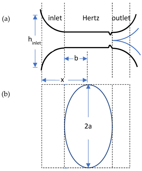
Figure 4.
Front view (a) and top view (b) of the fully flooded contact region.
For the Hertzian contact area, the film thickness is assumed to be equal to the central film thickness since it dominates. And the dielectric constant in this region is determined by the average surface temperature and mean contact pressure [80,81]. The total Hertzian contact area is .
For the outlet/cavitation regime, Crook assumes that the outlet section has two oil layers of equal thickness adhering to each disk [24]. The remainder of the outlet section is composed of air. Chittenden assumed the composite dielectric constant of the two-phase fluids was a function of the oil and air percentages [56]. In this research, it is assumed that there are three layers at the outlet, two layers of oil, and one layer of air in between (Figure 5). Each oil layer is assumed to be half of the central film thickness [24,69,80,81]. The pressure in the cavitated region of the lubricant film is approximately constant and near the atmospheric or ambient pressure [93].
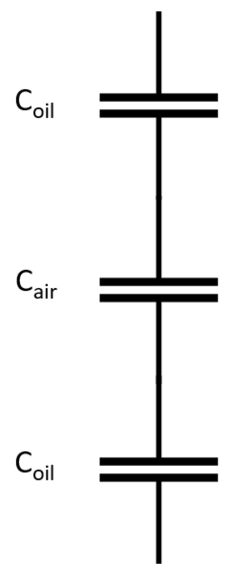
Figure 5.
Electronic network of the outlet region.
After applying the same geometry boundary at the outlet,
and combining (39), (40) and (44),
3.2. Starved
For the starved condition, the boundary of the inlet regime is determined by the inlet meniscus (Figure 6). The starvation model applied here is similar to that reported by Shetty [51]. The starvation condition is described with a dimensionless meniscus distance (, and is the meniscus distance). is the critical location of , which is a function of central film thickness [94]:
where is the dimensionless, fully flooded Hamrock and Dowson film thickness.
Figure 6.
Front view (a) and top view (b) of the starved contact region.
If the inlet distance m is less than , starvation occurs; otherwise, it is fully flooded. The starved dimensionless central film thickness can be expressed as
The analytical results and the experimental results were also found to be in good agreement for the film thickness reduction parameter [95].
Similarly, the inlet capacitance can be expressed as
The calculation of and are the same as in the fully flooded condition.
3.3. Mixed
The mixed model is inspired by Maruyama [23]. There are additional assumptions for the mixed regime:
- It is assumed there will be sufficient lubricant supply in the mixed regime; otherwise, it may cause premature bearing damage;
- It is assumed that there is no tribofilm formation on the surface. Tribofilms significantly increase contact resistance.
Surface asperity contact frequently occurs in the mixed mode regime, as illustrated in Figure 7a. The contact area is modeled as a resistor, and the separated area is modeled as a capacitor, as shown in Figure 7b. Resistors and capacitors are connected in parallel. The breakdown ratio [23] is defined as
Figure 7.
Illustration (a) and electronic network (b) of the mixed mode.
A simplified geometry model is shown in Figure 8. The inlet and outlet are the same in the fully flooded conditions. Only the Hertzian region needs to be modified.
In this regime, the admittance (inverse of impedance ) needs to be measured since the capacitors connect in parallel with the resistor.
The contact resistance and capacitance are calculated as a function of admittance and phase angle.
The model for fully flooded, starved, and mixed lubrication conditions is a proposal in the current research. Its accuracy relies on the precise dielectric constant of lubricants under high pressure and elevated temperature. The model evaluation and comparison will be included in the future work.

Figure 8.
Front view (a) and top view (b) of the mixed mode.
3.4. Program Flow Chart of Film Thickness Measurement
The procedures of film thickness measurement are illustrated in Figure 9.
- (1)
- Measure the background impedance and admittance using a hybrid bearing under the same contact pressure;
- (2)
- Measure both the static and dynamic impedance and admittance using the testing bearing;
- (3)
- If the electrical contact resistance is finite, the bearing is in the mixed mode. The and are calculated with admittance. Then, the breakdown ratio and the central film thickness are calculated. The program ends;
- (4)
- If the electrical contact resistance approaches infinity, the bearing is in either fully flooded or starved mode. and are calculated to determine the starvation degree. If < , calculate the film thickness with the starved model. Otherwise, use the fully flooded model.

Figure 9.
Program flow chart of film thickness measurement.
4. Dielectric Constant of Lubricants
Models and measurements of dielectric constants of lubricants are summarized in Table 4. For non-polar base oils, the classic Clausius–Mossotti (CM) relationship was suggested by many authors [56,58,69,72,76,91,96,97]. Paraffinic-based mineral oil and PAO can be considered a non-polar group. The CM equation describes the dielectric constant as a function of density. A widely applied relationship between density and pressure was described by Dowson and Higginson [98]. However, its validity under high pressure is doubtful. Bair [99] claimed that the Tait equation [100] resulted in higher accuracy than Dowson and Higginson’s equation for EHL calculations in the absence of compressibility data.
Table 4.
Summary of dielectric constant models of lubricants.
However, the dielectric constant of polar lubricants does not change linearly with density. Polarity may be introduced by the aromatic/naphthenic content and additives, which leads to an increase in the dielectric constant [103]. In this case, the CM equation is no longer valid, while Onsager or Kirkwood relationships should be applied [58,77]. The dielectric constant of a grease differs from its base oil. Wilson found that the dielectric constant difference between grease and its base oil is around 10% [20]. It may be attributed to the polar constituents and the presence of soap fiber fragments.
There are some efforts to correlate both the rheological and dielectric behaviors of lubricants. For dielectric loss, the surrounding liquid medium offers a resistance to these motions that is roughly proportional to its viscosity [97]. Khanmamedov et al. found that there was a linear relationship between the oil viscosity and the temperature, corresponding to the maximum dielectric loss tangent with a fixed frequency of measurement [104]. Once the constant of proportionality has been determined, measurements of viscosity can be obtained from a measurement of the dynamic permittivity under pressure [99].
Dielectric relaxation time can be correlated with fluid viscosity. The average motion of these neighboring molecules might be described by replacing them with a continuous medium with the properties of a macroscopic viscous fluid. This possibility leads to the model developed by Debye [105], in which a dipolar molecule is considered to be a sphere moving in a continuous, viscous fluid and obeying the macroscopic equation of flow.
4.1. Revisiting Classic Dielectric Models
When deciding the approximate model for a given material, one has to judge (a) whether the basic model represents the actual material and (b) whether the mathematization holds for the given range of concern [106]. Here, different dielectric models are revisited. Classical theories calculate the relative permittivity with a continuum approach: the molecule is placed in a cavity surrounded by the material treated as a continuum. For a spherical-shaped sample, the general equation of relative permittivity is
where is the polarizability of the molecule; is the number density, and is the dimensionless dipole strength function.
When , the equation reduces to the Clausius–Mossotti (CM) equation. It is valid for non-polar molecules.
When , it equates to the Debye equation [105], where is the permanent dipole moment; is the Boltzmann constant, and is the temperature. It holds approximately for gases and dilute solutions of molecules carrying a permanent dipole. But, it is not applicable for polar liquids because of neglecting the inner field.
When , the resulting equation is the Onsager equation [107]. It accounts for the orientation polarization of a molecule influenced by the surrounding dielectric due to long-range interactions at high densities. The high-frequency relative permittivity is commonly calculated from the Maxwell relationship , where is the inner refractive index. It can also be calculated based on the CM equation. The Onsager equation works quite well for liquids when the dipole moment is not too high.
The Kirkwood–Fröhlich equation [108] accounts for short-range correlation by introducing the effect of angular correlations between dipolar molecules. The original model is too complicated to be applied to a real material. Valisko et al. [109] developed an empirical extension based on the Kirkwood–Fröhlich equation to calculate the relative permittivity of dipolar liquids and mixtures in terms of the molecular dipole moment, the refractive index, density, and temperature.
4.2. Evaluation of Dielectric Models
The density and permittivity of 57 non-polar and dipolar molecular liquids at different temperatures (143 sets, up to 100 °C) and pressures (555 sets, up to 500 MPa) were collected and analyzed [110]. However, no equation was found that could accurately predict the liquid permittivity in the range of the pressures and temperatures tested. Molecular liquids exhibit significantly larger pressure and temperature dependence on permittivity compared to density. This indicates the strong influence of these external factors on the molecular structure. While density remains relatively unaffected, permittivity can be dramatically altered by several factors, including volume change, molecular deformation, shifts in dipole–dipole interactions, conformational equilibrium changes, and even modifications to the structure of OH complexes.
4.3. Summary
The results of the evaluation and analysis herein suggest modifying the CM and Onsager models with measured data. An engineering model with better accuracy can then be developed. Direct measurements of the dielectric constant under elevated temperature and high contact pressure are recommended for model validation.
5. Grease Starvation Factor
Table 5 summarizes different starvation models. These models collectively account for the factors perceived to influence the starvation of oil and grease-lubricated contacts. Starvation models have been proposed by many authors, based on either benchmark or full-bearing test results (both experimental and simulation results). Wedeven [111], Hamrock, and Dowson [94] proposed starvation models as a function of inlet meniscus distance. Some models have been discussed in the previous section. Cann [8] conducted the experiments on an oil-lubricated optical EHL rig and developed a starvation criterion as a function of lubricant volume, contact width, surface tension, critical speed, and velocity. Cen [50] measured the grease film thickness in a deep-groove ball bearing using capacitance methods. It was found that the ratio between grease film and fully flooded film depended on speed, load, temperature, and grease properties.
Table 5.
Summary of different starvation models of both oil and grease.
Damiens and Van Zoelen [112,113] proposed that the film thickness decayed with time and revolutions. However, in the author’s opinion, it is the grease degradation or change in the permeability that leads to film thickness decay. Chiu [114] proposed a starvation model that claims that the decay is a function of surface tension. Wandel [116,117] concluded that the starvation and relubrication mechanisms in grease-lubricated oscillating bearings were highly dependent on the operating conditions and lubricant rheology. Masjedi [118] simulated the starvation effect in mixed EHL numerically. The starvation degree was strongly correlated with the lubricant mass flow rate for both point and line contacts. Zhang et al. studied the factors affecting grease film formation on an EHD optical rig [119]. The proposed film thickness model considered the factors of working conditions, grease type, and consistency.
Based on the discussion above, the following five parameters are chosen to develop a new dimensionless grease starvation model:
where is oil surface tension; is the permeability; is entrainment velocity; is the dynamic viscosity of the base oil, and is the semi-minor. After the unit and dimension analysis of each parameter as shown in Table 6, the following dimensionless model was proposed:
where and are fitting parameters.
Table 6.
Units and dimensions of parameters.
There are few papers mentioning the capacitive grease film measurements within a bearing. Most works focus on the oil film thickness measurement. The available capacitive film thickness data of grease-lubricated bearings were extracted from the literature [17,20,50,51,120]. These data originated from various types of bearings (ball bearing, SRB, CRB), running conditions, grease formulations, testing rigs, and capacitive film thickness models.
Entrainment velocity and the contact semi-minor are calculated from bearing geometry and working conditions. The Kinematic Walther equation and the 40° and 100 °C spec sheet viscosities were used to calculate the test temperature-dependent base-oil viscosity.
Data were collected at the start of the bleeding phase, at which time, the film thickness was relatively stable. The bearings ran for 20~100 h. It is assumed that no grease degradation occurred at this point.
The permeability of a lubricant varies with working conditions (pressure, temperature, and shear) as well as irrecoverable degradation (breakdown of the thickener structure and concentration gradient). Akchurin et al. [121] have captured these influences in terms of the “adjusted friction energy density” and a master curve. This curve relates permeability to adjusted friction energy density. These data are included in the analysis. Grease permeability captures the porous thickener structure and base-oil duality. It also influences the decay of a grease film and is indicative of mechanical degradation.
The surface tension of lubricants is a function of temperature. The data on grease base oil at room temperature can be found in the literature. The surface tensions of mineral oil, semi-synthetic oil, PAO, and ester are reported as 32.3, 32.3, 31.2, 28.9, and 31.8 mN/m, respectively [122]. Empirical results of Ross [123] show that surface tension varies linearly within the temperature range 20~160 °C. The average slope of 24 groups was found to be −0.081. Here, an engineering model to calculate the surface tension of grease base oil is proposed:
For mineral oil and PAO,
For ester,
The mineral oil model is assumed to be sufficient when the lubricant-specific surface tension is unknown.
The developed regression model is shown in Figure 10. A total of 113 data points were extracted from different authors. The R-squared value is 0.71, which is reasonably good. Interestingly, is also reported by Chen et al. [124] as a dimensionless capillary number through numerical analysis. It describes the competition between viscous and capillary forces, which affects the shape of the inlet meniscus. The model needs to be further polished with more accurate film thickness data, which could be included in future work.
Figure 10.
Developed regression model based on capacitive film thickness data [17,20,50,51,121].
6. Conclusions
This review focuses on the measurement of capacitive film thickness in grease-lubricated bearings. The current developments in capacitance measurements and models are evaluated. Key challenges are identified, and potential solutions are proposed. It is expected that this work will bring a deeper understanding of grease-lubrication mechanisms in rolling element bearings.
The main conclusions can be drawn as follows:
- (1)
- The mechanisms of mainstream electronic components in capacitance measurement were reviewed. For analyzing complex electrical behavior, the LCR meter and impedance analyzer seem to be more suitable. It enables more accurate capacitance measurement;
- (2)
- Current capacitive models and programs can only measure one or two lubrication regimes. A new capacitive model, electric network, and program flow chart to measure lubricant film thickness in fully flooded, starved, and mixed regimes was developed. It is more comprehensive compared to the literature models;
- (3)
- Current dielectric constant models were reviewed, and suitable ones for lubricants were proposed. Modifying the CM and Onsager models with measured data to develop an engineering model is suggested. It facilitates a more precise film thickness measurement;
- (4)
- A new dimensionless grease starvation model was developed based on the 113 literature capacitive film thickness data points from five different authors. It is a function of surface tension, entrainment velocity, contact geometry, dynamic viscosity, and permeability. The R-squared value of 0.71 indicated a strong correlation, considering the variability in bearing types, operating conditions, grease formulations, testing rigs, and capacitive film thickness models.
Funding
This research received no external funding.
Acknowledgments
The author would like to thank Ryan Evans for the support and permission to publish this work. The author is grateful for the discussions with William Hannon at The Timken Company.
Conflicts of Interest
The author was employed by The Timken Company. He declares that the research was conducted in the absence of any commercial or financial relationships that could be construed as a potential conflict of interest.
Nomenclature
| Contact ellipse semi-major: m | |
| Contact ellipse semi-minor: m | |
| Capacitance: F | |
| Total bearing capacitance: F | |
| Bearing capacitance: F | |
| Background capacitance: F | |
| Inner race capacitance: F | |
| Outer race capacitance: F | |
| Inlet region capacitance: F | |
| Hertzian contact region capacitance: F | |
| Outlet region capacitance: F | |
| Frequency: Hz | |
| Central film thickness: m | |
| Outer race central film thickness: m | |
| Inner race central film thickness: m | |
| Grease film thickness: m | |
| Fully flooded film thickness: m | |
| Dimensionless fully flooded film thickness | |
| Starved dimensionless central film thickness | |
| Current: Ampere | |
| Imaginary unit | |
| Permeability: m2 | |
| Inductance: H | |
| Dimensionless inlet distance | |
| Dimensionless inlet distance at boundary between fully flooded and starved conditions | |
| Refractive index | |
| Charge: C | |
| Effective radius of roller pair = : m | |
| Radii of cylinders or rollers in contact: m | |
| Effective radius in x direction: m | |
| Contact resistance: ohm | |
| Outer-race radius (rolling): m | |
| Inner-race radius (rolling): m | |
| Ball radius: m | |
| Entrainment velocity: m/s | |
| Voltage: Volt | |
| Reactance: ohm | |
| Admittance: S | |
| Impedance of each electric component: ohm | |
| Number of balls in the bearing | |
| Vacuum permittivity: F/m | |
| Dielectric constant of oil at ambient pressure | |
| Dielectric constant of oil at Hertzian contact pressure | |
| Dielectric constant of oil at outlet pressure | |
| Dielectric constant of air | |
| Breakdown ratio | |
| Density of lubricants: kg/m³ | |
| Surface Tension: N/m | |
| Dynamic viscosity: Pa·s | |
| Lubricant dynamic viscosity at outer race: Pa·s | |
| Lubricant dynamic viscosity at inner race: Pa·s | |
| Angular frequency: rad/s | |
| Phase angle: rad | |
| Starvation factor |
References
- Hamrock, B.; Dowson, D. Ball Bearing Lubrication: The Elastohydrodynamics of Elliptical Contacts; John Wiley & Sons: Hoboken, NJ, USA, 1981. [Google Scholar]
- Lugt, P. Grease Lubrication in Rolling Bearings; John Wiley & Sons: Hoboken, NJ, USA, 2012. [Google Scholar]
- Poll, G.; Li, X.; Bader, N.; Guo, F. Starved lubrication in rolling contacts—A review. Bear. World J. 2019, 4, 69–81. [Google Scholar]
- Albahrani, S.; Philippon, D.; Vergne, P.; Bluet, J. A review of in situ methodologies for studying elastohydrodynamic lubrication. Proc. Inst. Mech. Eng. Part J J. Eng. Tribol. 2016, 230, 86–110. [Google Scholar] [CrossRef]
- Liu, Y.; Zhang, Y.; Zhu, D.; Wang, Q. EHL Experimental Techniques and Experimental-Numerical Result Comparisons. In Proceedings of the STLE/ASME 2006 International Joint Tribology Conference, San Antonio, TX, USA, 23–25 October 2006; ASME: New York, NY, USA, 2006; Volume 2006, pp. 235–251. [Google Scholar] [CrossRef]
- Åström, H.; Isaksson, O.; Höglund, E. Video recordings of an EHD point contact lubricated with grease. Tribol. Int. 1991, 24, 179–184. [Google Scholar] [CrossRef]
- Cameron, A.; Gohar, R. Theoretical and experimental studies of the oil film in lubricated point contact. Proc. R. Soc. Lond. Ser. Math. Phys. Sci. 1966, 291, 520–536. [Google Scholar]
- Cann, P.; Damiens, B.; Lubrecht, A. The transition between fully flooded and starved regimes in EHL. Tribol. Int. 2004, 37, 859–864. [Google Scholar] [CrossRef]
- Cen, H.; Lugt, P.; Morales-Espejel, G. Film Thickness of Mechanically Worked Lubricating Grease at Very Low Speeds. Tribol. Trans. 2014, 57, 1066–1071. [Google Scholar] [CrossRef]
- Noda, T.; Shibasaki, K.; Miyata, S.; Taniguchi, M. X-ray CT Imaging of Grease Behavior in Ball Bearing and Numerical Validation of Multi-Phase Flows Simulation. Tribol. Online 2020, 15, 36–44. [Google Scholar] [CrossRef]
- Gray, W.; Dwyer-Joyce, R. In-situ measurement of the meniscus at the entry and exit of grease and oil lubricated rolling bearing contacts. Front. Mech. Eng. 2022, 8, 1056950. [Google Scholar] [CrossRef]
- Courtney-Pratt, J.; Tudor, G. An Analysis of the Lubrication between the Piston Rings and Cylinder Wall of a Running Engine. Proc. Inst. Mech. Eng. 1946, 155, 293–299. [Google Scholar] [CrossRef]
- Crook, A. Simulated gear-tooth contacts: Some experiments upon their lubrication and subsurface deformations. Proc. Inst. Mech. Eng. 1957, 171, 187–214. [Google Scholar] [CrossRef]
- Lord, J.; Larsson, R. Film-forming capability in rough surface EHL investigated using contact resistance. Tribol. Int. 2008, 41, 831–838. [Google Scholar] [CrossRef]
- Lane, T.; Hughes, J. A study of the oil-film formation in gears by electrical resistance measurements. Br. J. Appl. Phys. 1952, 3, 315–318. [Google Scholar] [CrossRef]
- Bader, N.; Furtmann, A.; Tischmacher, H.; Poll, G. Capacitances and lubricant film thicknesses of grease and oil lubricated bearings. In Proceedings of the STLE Annual Meeting & Exhibition, Atlanta, GA, USA, 21–25 May 2017. [Google Scholar]
- Zhang, X.; Glovnea, R. Grease film thickness measurement in rolling bearing contacts. Proc. Inst. Mech. Eng. Part J J. Eng. Tribol. 2021, 235, 1430–1439. [Google Scholar] [CrossRef]
- Cen, H.; Lugt, P.; Morales-Espejel, G. On the Film Thickness of Grease-Lubricated Contacts at Low Speeds. Tribol. Trans. 2014, 57, 668–678. [Google Scholar] [CrossRef]
- Wittek, E.; Kriese, M.; Tischmacher, H.; Gattermann, S.; Ponick, B.; Poll, G. Capacitances and lubricant film thicknesses of motor bearings under different operating conditions. In Proceedings of the The XIX International Conference on Electrical Machines—ICEM 2010, Rome, Italy, 6–8 September 2010; IEEE: Piscataway, NJ, USA, 2010; pp. 1–6. [Google Scholar] [CrossRef]
- Wilson, A. The Relative Thickness of Grease and Oil Films in Rolling Bearings. Proc. Inst. Mech. Eng. 1979, 193, 185–192. [Google Scholar] [CrossRef]
- Morales-Espejel, G.; Lugt, P.; Pasaribu, H.; Cen, H. Film thickness in grease lubricated slow rotating rolling bearings. Tribol. Int. 2014, 74, 7–19. [Google Scholar] [CrossRef]
- Leenders, P.; Houpert, L. Paper XXI(i) study of the lubricant film in rolling bearings; effects of roughness. In Fluid Film Lubrication–Osborne Reynolds Centenary; Tribology Series; Elsevier: Amsterdam, The Netherlands, 1987; Volume 11, pp. 629–638. [Google Scholar]
- Maruyama, T.; Maeda, M.; Nakano, K. Lubrication Condition Monitoring of Practical Ball Bearings by Electrical Impedance Method. Tribol. Online 2019, 14, 327–338. [Google Scholar] [CrossRef]
- Crook, A. The lubrication of rollers. Philos. Trans. R. Soc. Lond. Ser. Math. Phys. Sci. 1958, 250, 387–409. [Google Scholar]
- Cen, H.; Bai, D.; Chao, Y.; Li, Y.; Li, R. EHL film thickness in rolling element bearings evaluated by electrical capacitance method: A review. Tribol.-Mater. Surf. Interfaces 2021, 15, 55–77. [Google Scholar] [CrossRef]
- Glovnea, R.; Furtuna, M.; Nagata, Y.; Sugimura, J. Electrical Methods for the Evaluation of Lubrication in Elastohydrodynamic Contacts. Tribol. Online 2012, 7, 46–53. [Google Scholar] [CrossRef][Green Version]
- Appleby, M.; Choy, F.; Du, L.; Zhe, J. Oil debris and viscosity monitoring using ultrasonic and capacitance/inductance measurements. Lubr. Sci. 2013, 25, 507–524. [Google Scholar] [CrossRef]
- Prashad, H.; Rao, K. Analysis of Capacitive Effect and Life Estimation of Hydrodynamic Journal Bearings on Repeated Starts and Stops of a Machine Operating under the Influence of Shaft Voltages. Tribol. Trans. 1994, 37, 641–645. [Google Scholar] [CrossRef]
- Murali, S.; Choy, F.; Zhe, J.; Carletta, J.; Xia, X. Oil Debris Detection Using Static and Dynamic Capacitance Measurements. In Proceedings of the STLE/ASME 2008 International Joint Tribology Conference, Miami, FL, USA, 20–22 October 2008; ASMEDC: Houston, TX, USA, 2008; pp. 241–243. [Google Scholar] [CrossRef]
- Potyrailo, R.; Tokarev, I.; Go, S.; Ottikkutti, P.; Kuzhiyil, N.; Mihok, J.; Anzini, C.; Shartzer, S. Multivariable Electrical Resonant Sensors for Independent Quantitation of Aging and External Contaminants in Lubricating Oils. IEEE Sens. J. 2019, 19, 1542–1553. [Google Scholar] [CrossRef]
- Shi, H.; Yu, S.; Xie, Y.; Li, W.; Zhang, H.; Zheng, Y.; Zhang, S.; Li, G.; Sun, Y.; Chen, H. Comprehensive detection method for multi-contaminants in hydraulic oil based on inductance-resistance-capacitance analysis. Tribol. Int. 2022, 173, 107609. [Google Scholar] [CrossRef]
- Qian, M.; Ren, Y.; Feng, Z. Interference reducing by low-voltage excitation for a debris sensor with triple-coil structure. Meas. Sci. Technol. 2020, 31, 025103. [Google Scholar] [CrossRef]
- Qian, M.; Zhao, G.; Ren, Y.; Diao, W.; Feng, Z.; Li, M. Triple-Coil Inductive Debris Sensor with Special Shielded Coils for Depressing Interference of Dielectric Components. Procedia Manuf. 2019, 39, 1279–1288. [Google Scholar] [CrossRef]
- Wu, Y.; Zhang, H. Solid particles, water drops and air bubbles detection in lubricating oil using microfluidic inductance and capacitance measurements. J. Micromechanics Microengineering 2019, 29, 025011. [Google Scholar] [CrossRef]
- Yang, D.; Hu, Z.; Xiao, J. Research on capacitive sensor for online oil monitoring. In Proceedings of the 2011 Prognostics and System Health Managment Conference, Shenzhen, China, 24–25 May 2011; IEEE: Piscataway, NJ, USA, 2011; pp. 1–4. [Google Scholar] [CrossRef]
- Yang, D.; Zhang, X.; Hu, Z.; Yang, Y. Oil Contamination Monitoring Based on Dielectric Constant Measurement. In Proceedings of the 2009 International Conference on Measuring Technology and Mechatronics Automation, Zhangjiajie, China, 11–12 April 2009; IEEE: Piscataway, NJ, USA, 2009; pp. 249–252. [Google Scholar] [CrossRef]
- Xue, Q.; Ma, M.; Fan, W.; Sun, B.; Cui, Z.; Wang, H. Level set based image segmentation for oil film monitoring using ECT. In Proceedings of the 2016 IEEE International Instrumentation and Measurement Technology Conference Proceedings, Taipei, Taiwan, 23–26 May 2016; IEEE: Piscataway, NJ, USA, 2016; pp. 1–5. [Google Scholar] [CrossRef]
- Murali, S.; Xia, X.; Jagtiani, A.; Carletta, J.; Zhe, J. A Microfluidic Device for Wear Detection in Lubricants. In Proceedings of the ASME 2008 International Mechanical Engineering Congress and Exposition, Boston, MA, USA, 31 October–6 November 2008; ASMEDC: Houston, TX, USA, 2008; pp. 859–863. [Google Scholar] [CrossRef]
- Nihira, T.; Manabe, K.; Tadokoro, C.; Ozaki, S.; Nakano, K. Complex Impedance Measurement Applied to Short-Time Contact Between Colliding Steel Surfaces. Tribol. Lett. 2015, 57, 29. [Google Scholar] [CrossRef]
- Manabe, K.; Nakano, K. Breakdown of oil films and formation of residual films. Tribol. Int. 2008, 41, 1103–1113. [Google Scholar] [CrossRef]
- Maruyama, T.; Nakano, K. In Situ Quantification of Oil Film Formation and Breakdown in EHD Contacts. Tribol. Trans. 2018, 61, 1057–1066. [Google Scholar] [CrossRef]
- Nakano, K.; Akiyama, Y. Simultaneous measurement of film thickness and coverage of loaded boundary films with complex impedance analysis. Tribol. Lett. 2006, 22, 127–134. [Google Scholar] [CrossRef]
- Schirra, T.; Martin, G.; Vogel, S.; Kirchner, E. Ball Bearings as Sensors for Systematical Combination of Load and Failure Monitoring. In Proceedings of the DESIGN 2018 15th International Design Conference, Dubrovnik, Croatia, 21–24 May 2018; The Design Society: Glasgow, UK, 2018; pp. 3011–3022. [Google Scholar] [CrossRef]
- Schnabel, S.; Marklund, P.; Minami, I.; Larsson, R. Monitoring of Running-in of an EHL Contact Using Contact Impedance. Tribol. Lett. 2016, 63, 35. [Google Scholar] [CrossRef]
- Xie, K.; Liu, L.; Li, X.; Zhang, H. Non-contact resistance and capacitance on-line measurement of lubrication oil film in rolling element bearing employing an electric field coupling method. Measurement 2016, 91, 606–612. [Google Scholar] [CrossRef]
- Schritz, B.; Jones Jr, W.; Prahl, J.; Jansen, R. Parched elastohydrodynamic lubrication: Instrumentation and procedure. In Proceedings of the Annual Meeting of the Society of Tribologists and Lubrication Engineers, Ptuqadeiphia, PA, USA, 4–7 May 1991. [Google Scholar]
- Kingsbury, E.; Schritz, B.; Prahl, J. Parched Elasto Hydrodynamic Lubrication Film Thickness Measurement in an Instrument Ball Bearing. Tribol. Trans. 1990, 33, 11–14. [Google Scholar] [CrossRef]
- Franke, E.; Poll, G. Service life and lubrication conditions of different grease types in high-speed rolling bearings. In Lubrication at the Frontier: The Role of the Interface and Surface Layers in the Thin Film and Boundary Regime; Tribology Series; Elsevier: Amsterdam, The Netherlands, 1999; Volume 36, pp. 601–609. [Google Scholar] [CrossRef]
- Heemskerk, R.; Vermeiren, K.; Dolfsma, H. Measurement of Lubrication Condition in Rolling Element Bearings. ASLE Trans. 1982, 25, 519–527. [Google Scholar] [CrossRef]
- Cen, H.; Lugt, P. Film thickness in a grease lubricated ball bearing. Tribol. Int. 2019, 134, 26–35. [Google Scholar] [CrossRef]
- Shetty, P.; Meijer, R.; Osara, J.; Lugt, P. Measuring Film Thickness in Starved Grease-Lubricated Ball Bearings: An Improved Electrical Capacitance Method. Tribol. Trans. 2022, 65, 869–879. [Google Scholar] [CrossRef]
- Adabi, J.; Zare, F.; Ledwich, G.; Ghosh, A.; Lorenz, R. Bearing damage analysis by calculation of capacitive coupling between inner and outer races of a ball bearing. In Proceedings of the 2008 13th International Power Electronics and Motion Control Conference, Poznan, Poland, 1–3 September 2008; IEEE: Piscataway, NJ, USA, 2008; pp. 903–907. [Google Scholar] [CrossRef]
- Attia, A.; El-Bahloul, A. Lubrication Capacity of Gears of Circular-Arc Tooth-Profile. J. Tribol. 1988, 110, 699–703. [Google Scholar] [CrossRef]
- Bates, T.; Benwell, S. Effect of Oil Rheology on Journal Bearing Performance Part 3—Newtonian Oils in the Connecting-Rod Bearing of an Operating Engine. SAE Trans. 1988, 97, 308–320. [Google Scholar]
- Cen, H.; Lugt, P. Replenishment of the EHL contacts in a grease lubricated ball bearing. Tribol. Int. 2020, 146, 106064. [Google Scholar] [CrossRef]
- Chittenden, R.; Dowson, D.; Taylor, C. Elastohydrodynamic Film Thickness in Concentrated Contacts: Part 1: Experimental Investigation for Lubricant Entrainment Aligned with the Major Axis of the Contact Ellipse. Proc. Inst. Mech. Eng. Part C J. Mech. Eng. Sci. 1986, 200, 207–217. [Google Scholar] [CrossRef]
- Cho, M.-R.; Han, D.-C.; Choi, J.-K. Oil Film Thickness in Engine Connecting-Rod Bearing with Consideration of Thermal Effects: Comparison between Theory and Experiment. J. Tribol. 1999, 121, 901–907. [Google Scholar] [CrossRef]
- Chua, W.; Stachowiak, G. The Study of the Dynamic Thickness of Organic Boundary Films Under Metallic Sliding Contact. Tribol. Lett. 2010, 39, 151–161. [Google Scholar] [CrossRef]
- Cui, Z.; Wang, H.; Yang, C.; Xu, Y. Estimation of in-tube oil film thickness using electrical capacitance tomography. In Proceedings of the 2013 IEEE International Instrumentation and Measurement Technology Conference (I2MTC), Minneapolis, MN, USA, 6–9 May 2013; IEEE: Piscataway, NJ, USA, 2013; pp. 1–4. [Google Scholar] [CrossRef]
- Dhar, A.; Agarwal, A.; Saxena, V. Measurement of Lubricating Oil Film Thickness between Piston Ring-liner Interface in an Engine Simulator; SAE Technical Paper 2008-28-0071; SAE International: Warrendale, PA, USA, 2008. [Google Scholar] [CrossRef]
- Dhar, A.; Agarwal, A.; Saxena, V. Measurement of dynamic lubricating oil film thickness between piston ring and liner in a motored engine. Sens. Actuators Phys. 2009, 149, 7–15. [Google Scholar] [CrossRef]
- Garcia-Atance Fatjo, G.; Smith, E.; Sherrington, I. Mapping lubricating film thickness, film extent and ring twist for the compression-ring in a firing internal combustion engine. Tribol. Int. 2014, 70, 112–118. [Google Scholar] [CrossRef]
- Gatzen, M.; Pape, F.; Bruening, C.; Gatzen, H.; Arlinghaus, H.; Poll, G. Correlation between performance and boundary layers in high speed bearings lubricated with polymer-enhanced greases. Tribol. Int. 2010, 43, 981–989. [Google Scholar] [CrossRef]
- Gouda, B.; Tandon, N.; Pandey, R.; Babu, C. Design and development of a test rig for performance evaluation of ball bearings. In Proceedings of the Advances in Mechanical Engineering, Industrial Informatics and Management (AMEIIM2022), Raipur, India, 25–26 February 2022; p. 020006. [Google Scholar] [CrossRef]
- Gouda, B.; Tandon, N.; Pandey, R.; Babu, C. Performance improvement of a radial ball bearing using a micro-groove on stationary outer race. Proc. Inst. Mech. Eng. Part C J. Mech. Eng. Sci. 2022, 236, 11521–11536. [Google Scholar] [CrossRef]
- Grice, N.; Sherrington, I. An Experimental Investigation into the Lubrication of Piston Rings in an Internal Combustion Engine-Oil Film Thickness Trends, Film Stability and Cavitation; SAE Technical Paper 930688; SAE International: Warrendale, PA, USA, 1993. [Google Scholar] [CrossRef]
- Gui, C.; Liu, K. Effect of surface roughness on the lubrication properties of the piston ring and cylinder of an engine, and calculation of lubrication and power loss analysis of piston-ring pack of a S195 diesel engine. Lubr. Sci. 1992, 4, 263–275. [Google Scholar] [CrossRef]
- Guo, L.; Mol, H.; Nijdam, T.; de Vries, L.; Bongaerts, J. Study on the electric discharge behaviour of a single contact in EV motor bearings. Tribol. Int. 2023, 187, 108743. [Google Scholar] [CrossRef]
- Hamilton, G.; Moore, S. Deformation and pressure in an elastohydrodynamic contact. Proc. R. Soc. Lond. Math. Phys. Sci. 1971, 322, 313–330. [Google Scholar] [CrossRef]
- Hamilton, G.; Moore, S. First Paper: Measurement of the Oil-Film Thickness between the Piston Rings and Liner of a Small Diesel Engine. Proc. Inst. Mech. Eng. 1974, 188, 253–261. [Google Scholar] [CrossRef]
- Hamilton, G.; Moore, S. Second Paper: Comparison between Measured and Calculated Thicknesses of the Oil-Film Lubricating Piston Rings. Proc. Inst. Mech. Eng. 1974, 188, 262–268. [Google Scholar] [CrossRef]
- Hegedus, P. Evaluation and Prediction of Elastohydrodynamic Lubrication Film Thickness under Conditions of Severe Sliding and Zero Entrainment. Ph.D. Thesis, Case Western Reserve University, Cleveland, OH, USA, 2018. [Google Scholar]
- Hemingway, E. The Measurement of Film Thickness in Thrust Bearings and the Deflected Shape of ‘Parallel’ Surface Thrust Pads. Proc. Inst. Mech. Eng. 1965, 180, 1025–1034. [Google Scholar] [CrossRef]
- Hoehn, B.; Michaelis, K.; Mayer, J.; Weigl, A. Influence of surface velocity directions on lubricant film formation in EHL point contacts. Tribol. Int. 2012, 47, 9–15. [Google Scholar] [CrossRef]
- Irani, K.; Pekkari, M.; Ångström, H. Oil film thickness measurement in the middle main bearing of a six-cylinder supercharged 9 litre diesel engine using capacitive transducers. Wear 1997, 207, 29–33. [Google Scholar] [CrossRef]
- Jablonka, K.; Glovnea, R.; Bongaerts, J. Evaluation of EHD films by electrical capacitance. J. Phys. D Appl. Phys. 2012, 45, 385301. [Google Scholar] [CrossRef]
- Jablonka, K.; Glovnea, R.; Bongaerts, J.; Morales-Espejel, G. The effect of the polarity of the lubricant upon capacitance measurements of EHD contacts. Tribol. Int. 2013, 61, 95–101. [Google Scholar] [CrossRef]
- Horowitz, P.; Hill, W. The Art of Electronics, 3rd ed.; 19th printing; Cambridge University Press: New York, NY, USA, 2022; ISBN 978-0-521-80926-9. [Google Scholar]
- Moore, S. Piston ring lubrication in a two-stroke diesel engine. Wear 1981, 72, 353–369. [Google Scholar] [CrossRef]
- Dyson, A.; Naylor, H.; Wilson, A. Paper 10: The measurement of oil-film thickness in elastohydrodynamic contacts. Proc. Inst. Mech. Eng. Conf. Proc. 1965, 180, 119–134. [Google Scholar] [CrossRef]
- ten Napel, W.; Bosma, R. The Influence of Surface Roughness on the Capacitive Measurement of Film Thickness in Elastohydrodynamic Contacts. Proc. Inst. Mech. Eng. 1970, 185, 635–639. [Google Scholar] [CrossRef]
- Wen, B.; Ren, H.; Dang, P.; Hao, X.; Han, Q. Measurement and calculation of oil film thickness in a ball bearing. Ind. Lubr. Tribol. 2018, 70, 1500–1508. [Google Scholar] [CrossRef]
- Zhang, P.; Zhu, B.; Liu, S. Study of measuring EHL oil-film thickness with electric capacity method. Lubr. Eng. 1982, 7, 16–22. [Google Scholar]
- Schirra, T.; Martin, G.; Puchtler, S.; Kirchner, E. Electric impedance of rolling bearings—Consideration of unloaded rolling elements. Tribol. Int. 2021, 158, 106927. [Google Scholar] [CrossRef]
- Schneider, V.; Bader, N.; Liu, H.; Poll, G. Method for in situ film thickness measurement of ball bearings under combined loading using capacitance measurements. Tribol. Int. 2022, 171, 107524. [Google Scholar] [CrossRef]
- Schneider, V.; Liu, H.; Bader, N.; Furtmann, A.; Poll, G. Empirical formulae for the influence of real film thickness distribution on the capacitance of an EHL point contact and application to rolling bearings. Tribol. Int. 2021, 154, 106714. [Google Scholar] [CrossRef]
- Magdun, O.; Binder, A. Calculation of roller and ball bearing capacitances and prediction of EDM currents. In Proceedings of the 2009 35th Annual Conference of IEEE Industrial Electronics, Porto, Portugal, 3–5 November 2009; IEEE: Piscataway, NJ, USA, 2009; pp. 1051–1056. [Google Scholar] [CrossRef]
- Hunter, S. Oil Film Thickness Measurement and Analysis for an Angular Contact Ball Bearing Operating in Parched Elastohydrodynamic Lubrication. In Proceedings of the Institution of Mechanical Engineers, International Conference, IMechE 1987-5, Cincinnati, OH, USA, 14–17 June 1987; Case Western Reserve University: Cleveland, OH, USA, 1987. [Google Scholar]
- Bartz, M. Lubricant Film Formation in Grease Lubricated High Speed Spindle Bearings. Ph.D. Thesis, University of Hanover, Hanover, Germany, 1996. [Google Scholar]
- Gemeinder, Y.; Schuster, M.; Radnai, B.; Sauer, B.; Binder, A. Calculation and validation of a bearing impedance model for ball bearings and the influence on EDM-currents. In Proceedings of the 2014 International Conference on Electrical Machines (ICEM), Berlin, Germany, 2–5 September 2014; IEEE: Piscataway, NJ, USA, 2014; pp. 1804–1810. [Google Scholar] [CrossRef]
- Gonda, A. Determination of Rolling Bearing Electrical Capacitances with Experimental and Numerical Investigation Methods. Ph.D. Thesis, Rheinland-Pfälzische Technische Universität Kaiserslautern-Landau, Kaiserslautern, Germany, 2024. [Google Scholar]
- Crook, A. The lubrication of rollers II. Film thickness with relation to viscosity and speed. Philos. Trans. R. Soc. Lond. Ser. Math. Phys. Sci. 1961, 254, 223–236. [Google Scholar]
- Dowson, D.; Higginson, G. Elasto-Hydrodynamic Lubrication: International Series on Materials Science and Technology; Elsevier: Amsterdam, The Netherlands, 2014. [Google Scholar]
- Hamrock, B.; Dowson, D. Isothermal Elastohydrodynamic Lubrication of Point Contacts: Part IV—Starvation Results. J. Lubr. Technol. 1977, 99, 15–23. [Google Scholar] [CrossRef]
- Nogi, T. An Analysis of Starved EHL Point Contacts with Reflow. Tribol. Online 2015, 10, 64–75. [Google Scholar] [CrossRef]
- Zhang, X.; Jablonka, K.; Glovnea, R. Experimental Rig for Measuring Lubricant Film Thickness in Rolling Bearings. Appl. Mech. Mater. 2014, 658, 381–386. [Google Scholar] [CrossRef]
- Bondi, A. Physical Chemistry of Lubricating Oils; Reinhold Publishing Corporation: Washington, DC, USA, 1951. [Google Scholar]
- Dowson, D. Elastohydrodynamic lubrication. In The Fundamentals of Roller and Gear Lubrication; Pergamon Press: Oxford, UK, 1966. [Google Scholar]
- Bair, S. High Pressure Rheology for Quantitative Elastohydrodynamics; Elsevier: Amsterdam, The Netherlands, 2019. [Google Scholar]
- Hirschfelder, J.; Curtiss, C.; Bird, R. The Molecular Theory of Gases and Liquids; John Wiley & Sons: Hoboken, NJ, USA, 1964. [Google Scholar]
- Galvin, G.; Naylor, H.; Wilson, A. Paper 14: The Effect of Pressure and Temperature on Some Properties of Fluids of Importance in Elastohydrodynamic Lubrication. Inst. Mech. Eng. Conf. Proc. 1963, 178, 283–290. [Google Scholar] [CrossRef]
- Fuks, I.; Gundyrev, A.; Shekhter, Y.; Perekrestova, V.; Fedorova, T.; Kartinin, B. Chemical composition of dispersion medium and dielectric constant of lithium greases. Chem. Technol. Fuels Oils 1974, 10, 480–483. [Google Scholar] [CrossRef]
- Carey, A. The dielectric constant of lubrication oils. Comput. Syst. Inc. 1998, 835, 675–683. [Google Scholar]
- Khanmamedov, S.; Bardetskii, A. Relation between dielectric and viscosity characteristics of turbine oils. Chem. Technol. Fuels Oils 1988, 24, 209–211. [Google Scholar] [CrossRef]
- Debye, P. Polar Molecules; Dover: New York, NY, USA, 1929. [Google Scholar]
- Fröhlich, H. Theory of Dielectrics: Dielectric Constant and Dielectric Loss; Clarendon Press: Oxford, UK, 1958. [Google Scholar]
- Onsager, L. Electric moments of molecules in liquids. J. Am. Chem. Soc. 1936, 58, 1486–1493. [Google Scholar] [CrossRef]
- Kirkwood, J. The dielectric polarization of polar liquids. J. Chem. Phys. 1939, 7, 911–919. [Google Scholar] [CrossRef]
- Valiskó, M.; Boda, D.; Liszi, J.; Szalai, I. Relative permittivity of dipolar liquids and their mixtures. Comparison of theory and experiment. Phys. Chem. Chem. Phys. 2001, 3, 2995–3000. [Google Scholar] [CrossRef]
- Kiselev, V.; Kornilov, D.; Konovalov, A. Changes in Permittivity and Density of Molecular Liquids under High Pressure. J. Phys. Chem. B 2014, 118, 3702–3709. [Google Scholar] [CrossRef]
- Wedeven, L.; Evans, D.; Cameron, A. Optical analysis of ball bearing starvation. J. Lubr. Technol. 1971, 93, 349–361. [Google Scholar] [CrossRef]
- Damiens, B.; Venner, C.; Cann, P.; Lubrecht, A. Starved Lubrication of Elliptical EHD Contacts. J. Tribol. 2004, 126, 105–111. [Google Scholar] [CrossRef]
- van Zoelen, M.; Venner, C.; Lugt, P. Prediction of film thickness decay in starved elasto-hydrodynamically lubricated contacts using a thin layer flow model. Proc. Inst. Mech. Eng. Part J J. Eng. Tribol. 2009, 223, 541–552. [Google Scholar] [CrossRef]
- Chiu, Y. An Analysis and Prediction of Lubricant Film Starvation in Rolling Contact Systems. ASLE Trans. 1974, 17, 22–35. [Google Scholar] [CrossRef]
- Chevalier, F.; Lubrecht, A.; Cann, P.; Colin, F.; Dalmaz, G. Film thickness in starved EHL point contacts. J. Tribol. 1998, 120, 126–133. [Google Scholar] [CrossRef]
- Wandel, S.; Bader, N.; Schwack, F.; Glodowski, J.; Lehnhardt, B.; Poll, G. Starvation and relubrication mechanisms in grease lubricated oscillating bearings. Tribol. Int. 2022, 165, 107276. [Google Scholar] [CrossRef]
- Wandel, S.; Bader, N.; Glodowski, J.; Lehnhardt, B.; Leckner, J.; Schwack, F.; Poll, G. Starvation and Re-lubrication in Oscillating Bearings: Influence of Grease Parameters. Tribol. Lett. 2022, 70, 114. [Google Scholar] [CrossRef]
- Masjedi, M.; Khonsari, M. A study on the effect of starvation in mixed elastohydrodynamic lubrication. Tribol. Int. 2015, 85, 26–36. [Google Scholar] [CrossRef]
- Zhang, Z.; Wang, Y.; Lin, J.; Wang, D. Study on Factors Influencing Film Formation of Grease and Calculation Model for Grease Film Thickness. Lubricants 2022, 10, 123. [Google Scholar] [CrossRef]
- Zhou, Y.; Bosman, R.; Lugt, P. An Experimental Study on Film Thickness in a Rolling Bearing for Fresh and Mechanically Aged Lubricating Greases. Tribol. Trans. 2019, 62, 557–566. [Google Scholar] [CrossRef]
- Akchurin, A.; Ende, D.; Lugt, P. Modeling impact of grease mechanical ageing on bleed and permeability in rolling bearings. Tribol. Int. 2022, 170, 107507. [Google Scholar] [CrossRef]
- Zhang, Q.; Mugele, F.; Van Den Ende, D.; Lugt, P. A Model Configuration For Studying Stationary Grease Bleed In Rolling Bearings. Tribol. Trans. 2021, 64, 1127–1137. [Google Scholar] [CrossRef]
- Ross, S. Variation with Temperature of Surface Tension of Lubricating Oils; NACA: Washington, DC, USA, 1950. [Google Scholar]
- Chen, H.; Wang, W.; Liang, H.; Zhao, Z. Patterns of interfacial flow around a lubricated rolling point contact region. Phys. Fluids 2021, 33, 102118. [Google Scholar] [CrossRef]
Disclaimer/Publisher’s Note: The statements, opinions and data contained in all publications are solely those of the individual author(s) and contributor(s) and not of MDPI and/or the editor(s). MDPI and/or the editor(s) disclaim responsibility for any injury to people or property resulting from any ideas, methods, instructions or products referred to in the content. |
© 2024 by the author. Licensee MDPI, Basel, Switzerland. This article is an open access article distributed under the terms and conditions of the Creative Commons Attribution (CC BY) license (https://creativecommons.org/licenses/by/4.0/).