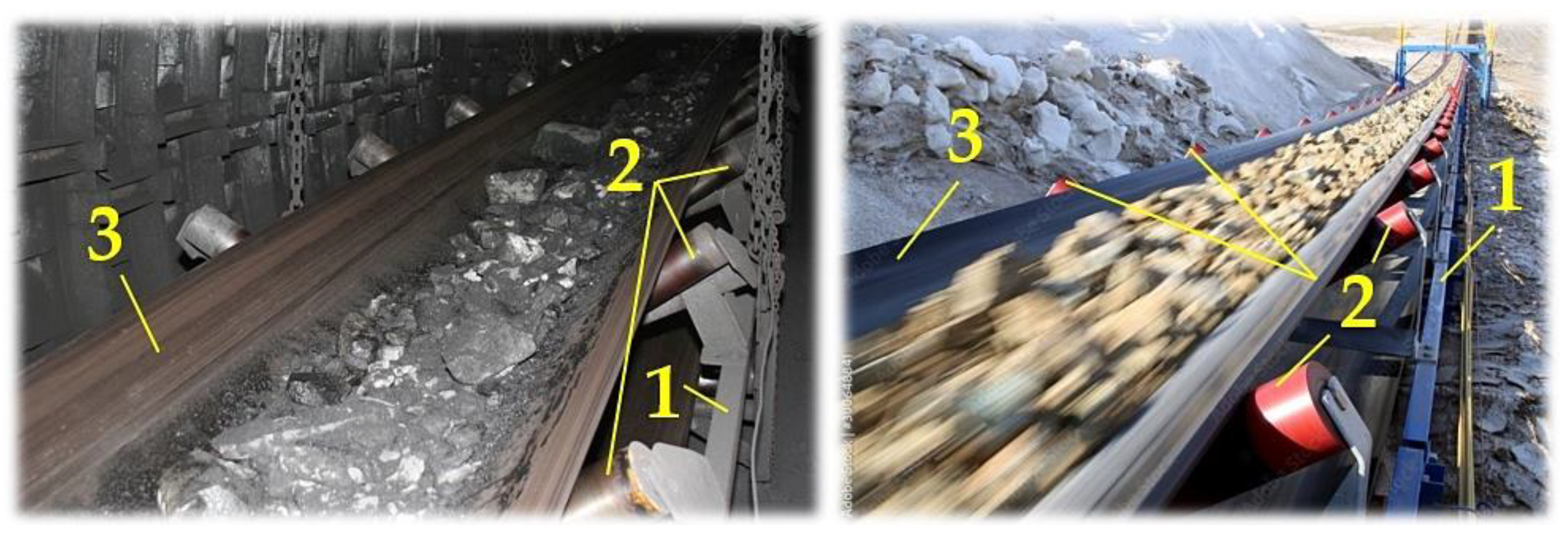
Figure 1.
The endless loop of a conveyor belt supported by conveyor rollers. 1—conveyor line, 2—conveyor rollers, 3—conveyor belt.
Figure 1.
The endless loop of a conveyor belt supported by conveyor rollers. 1—conveyor line, 2—conveyor rollers, 3—conveyor belt.
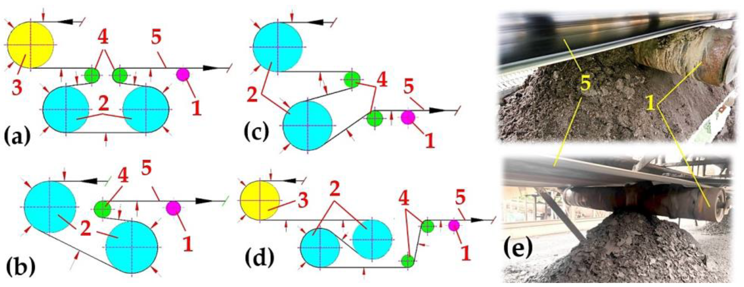
Figure 2.
Two-drum driving station (a) type Ω, (b) type C, (c) without a boom, (d) type S, (e) transported material stuck on the casing of the conveyor roller. 1—conveyor roller, 2—drive drum, 3—dump drum, 4—transmission drum, 5—conveyor belt.
Figure 2.
Two-drum driving station (a) type Ω, (b) type C, (c) without a boom, (d) type S, (e) transported material stuck on the casing of the conveyor roller. 1—conveyor roller, 2—drive drum, 3—dump drum, 4—transmission drum, 5—conveyor belt.
Figure 3.
(a) Structural 3D design of a laboratory machine—front view, (b) conveyor roller placed in the trestle of a fixed conveyor idler, (c) drive frame, (d) laboratory machine—rear view. 1—steel frame, 2—fixed conveyor idler, 3—conveyor roller, 4—driven pulley, 5—V-belt, 6—plastic bracket, 7—drive support frame, 8—electric motor support device, 9—threaded rod.
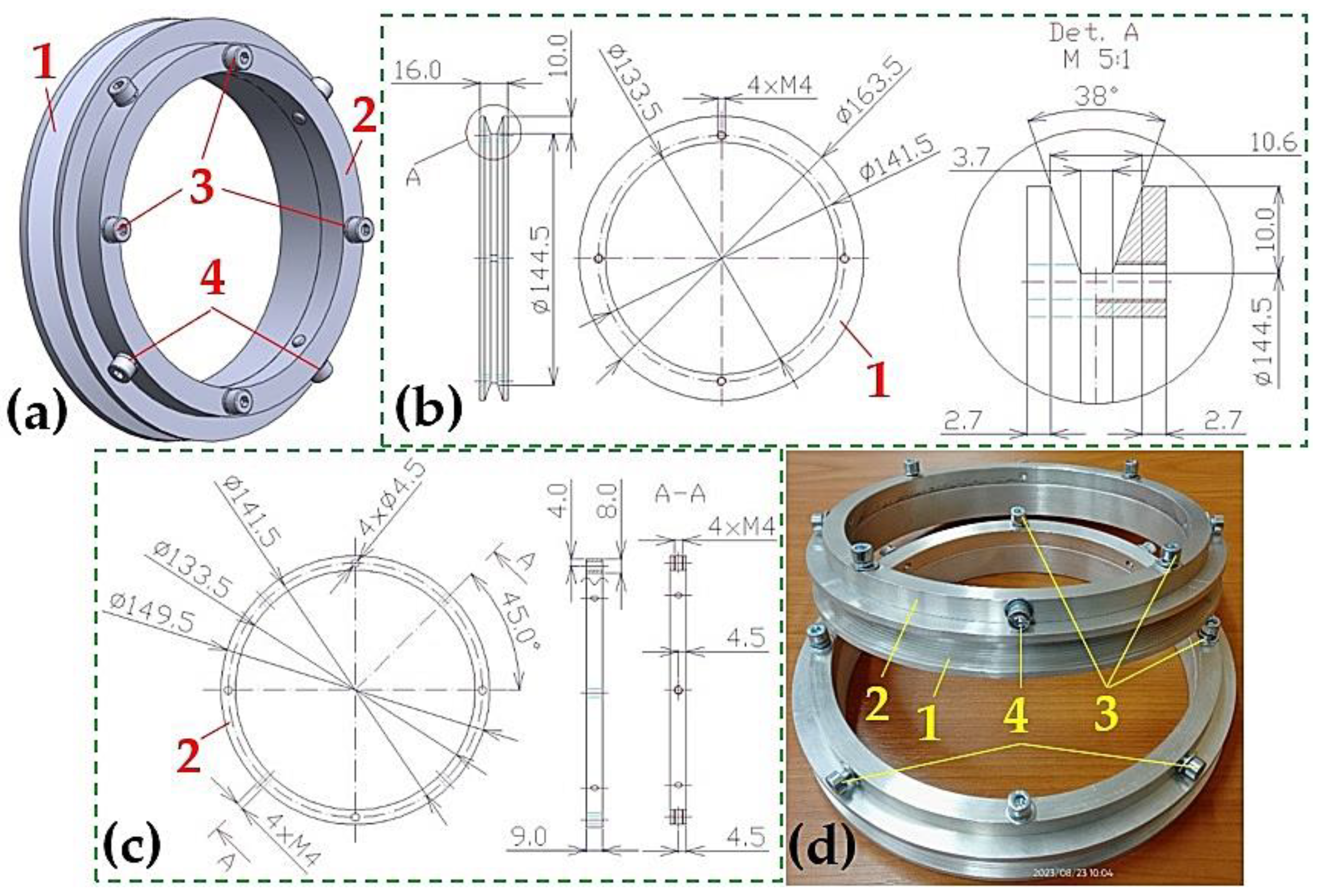
Figure 4.
(a) A 3D model of V-belt pulley assembly, (b) the dimensions of the pulley, (c) the dimensions of the flange for the ϕ133 mm conveyor roller, (d) manufactured V-belt pulley assembly. 1—V-belt pulley, 2—flange, 3—screw M4 × 16 DIN 912, 4—screw M4 × 10 DIN 912.
Figure 4.
(a) A 3D model of V-belt pulley assembly, (b) the dimensions of the pulley, (c) the dimensions of the flange for the ϕ133 mm conveyor roller, (d) manufactured V-belt pulley assembly. 1—V-belt pulley, 2—flange, 3—screw M4 × 16 DIN 912, 4—screw M4 × 10 DIN 912.
Figure 5.
(a) A 3D model of the V-belt pulley assembly, (b) flange dimensions for ϕ108 mm conveyor roller, (c) manufacture V-belt pulley assembly, (d) a 3D model of the V-belt pulley assembly, (e) flange dimensions for ϕ89 mm conveyor roller, (f) manufactured V-belt pulley assembly. 1—V-belt pulley, 2—flange, 3—screw M4 × 16 DIN 912, 4—screw M4 × 25 DIN 912 (screw M4 × 35 DIN 933).
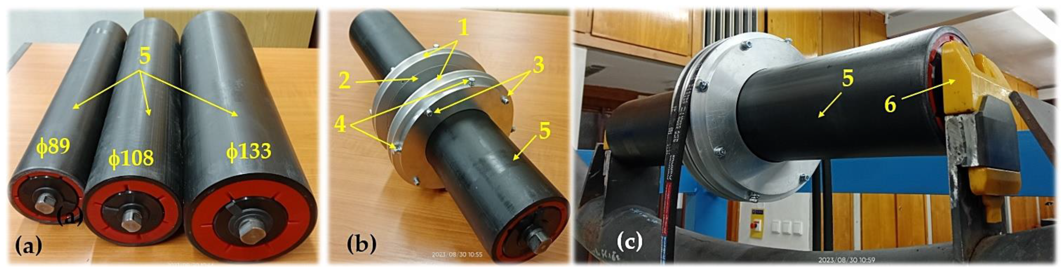
Figure 6.
Conveyor roller (a) steel, (b) rubberized, (c) a 3D model of a conveyor roller fitted with two pieces of the V-belt pulley assembly. 1—V-belt pulley, 2—flange, 3—screw M4 × 16 DIN 912, 4—screw M4 × 10 (25) DIN 912 (M4 × 35 DIN 933), 5—ϕ133 mm conveyor roller (or ϕ108 mm or ϕ89 mm).
Figure 6.
Conveyor roller (a) steel, (b) rubberized, (c) a 3D model of a conveyor roller fitted with two pieces of the V-belt pulley assembly. 1—V-belt pulley, 2—flange, 3—screw M4 × 16 DIN 912, 4—screw M4 × 10 (25) DIN 912 (M4 × 35 DIN 933), 5—ϕ133 mm conveyor roller (or ϕ108 mm or ϕ89 mm).
Figure 7.
(a) Plastic conveyor roller, (b) conveyor roller fitted with two pieces of a V-belt pulley assembly, (c) roller axle placed in a plastic bracket. 1—V-belt pulley, 2—flange, 3—screw M4 × 16 DIN 912, 4—screw M4 × 10 (25) DIN 912 (M4 × 35 DIN 933), 5—ϕ133 mm conveyor roller (or ϕ108 mm, or ϕ89 mm), 6—plastic bracket to hold the roller axles.
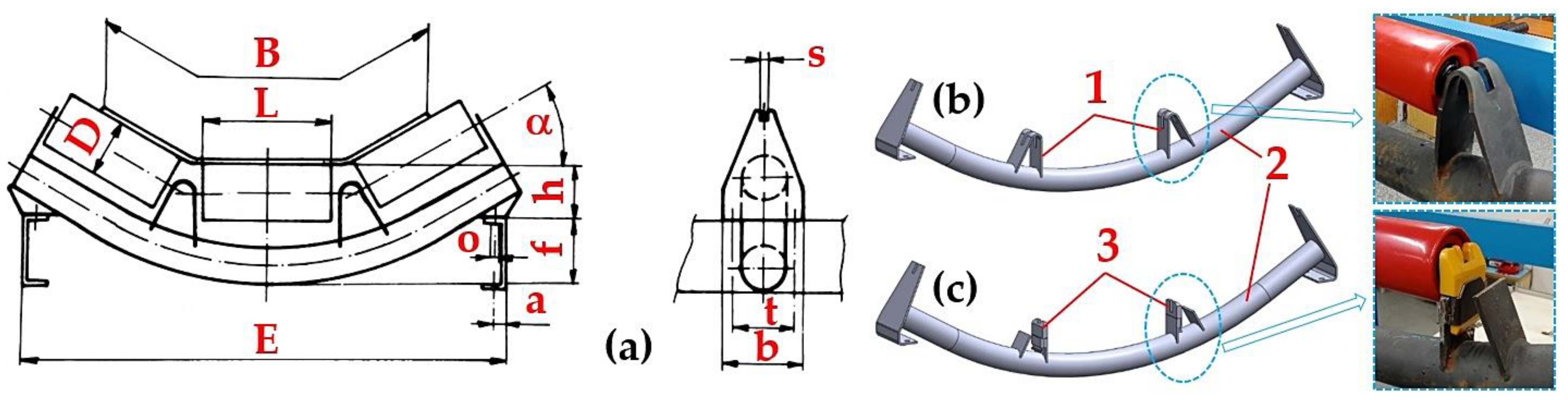
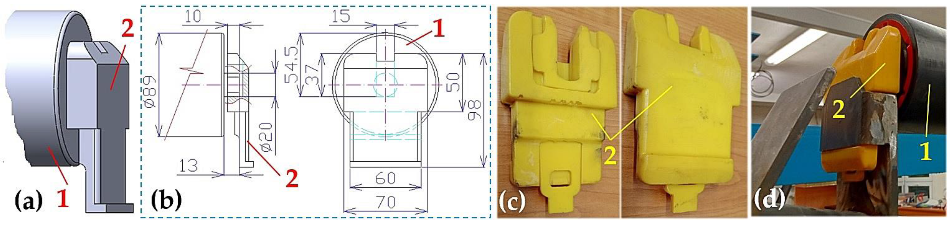
Figure 8.
Plastic bracket for the conveyor roller axle inserted into a modified trestle of a fixed roller idler (a) 3D structural design, (b) 3D structural design, (c) the implemented solution of the plastic bracket, plastic holder, (d) conveyor roller mounted in the trestle of a fixed roller idler. 1—conveyor roller, 2—plastic bracket.
Figure 9.
Measuring chain for detecting and recording the vibrations of rotating rollers on a laboratory machine.
Figure 9.
Measuring chain for detecting and recording the vibrations of rotating rollers on a laboratory machine.
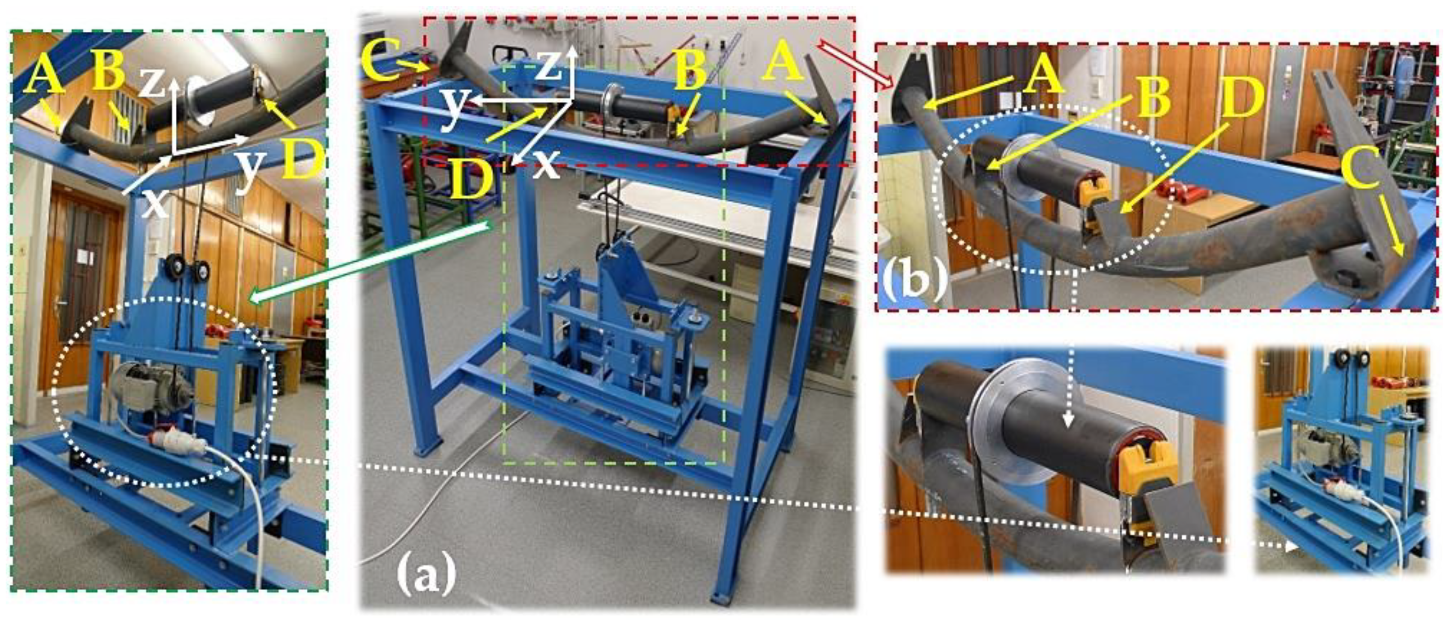
Figure 11.
(a) A laboratory machine used to measure the vibrations of the conveyor rollers; (b) measuring points A, B, C, and D on a fixed conveyor idler where accelerometers are placed.
Figure 11.
(a) A laboratory machine used to measure the vibrations of the conveyor rollers; (b) measuring points A, B, C, and D on a fixed conveyor idler where accelerometers are placed.
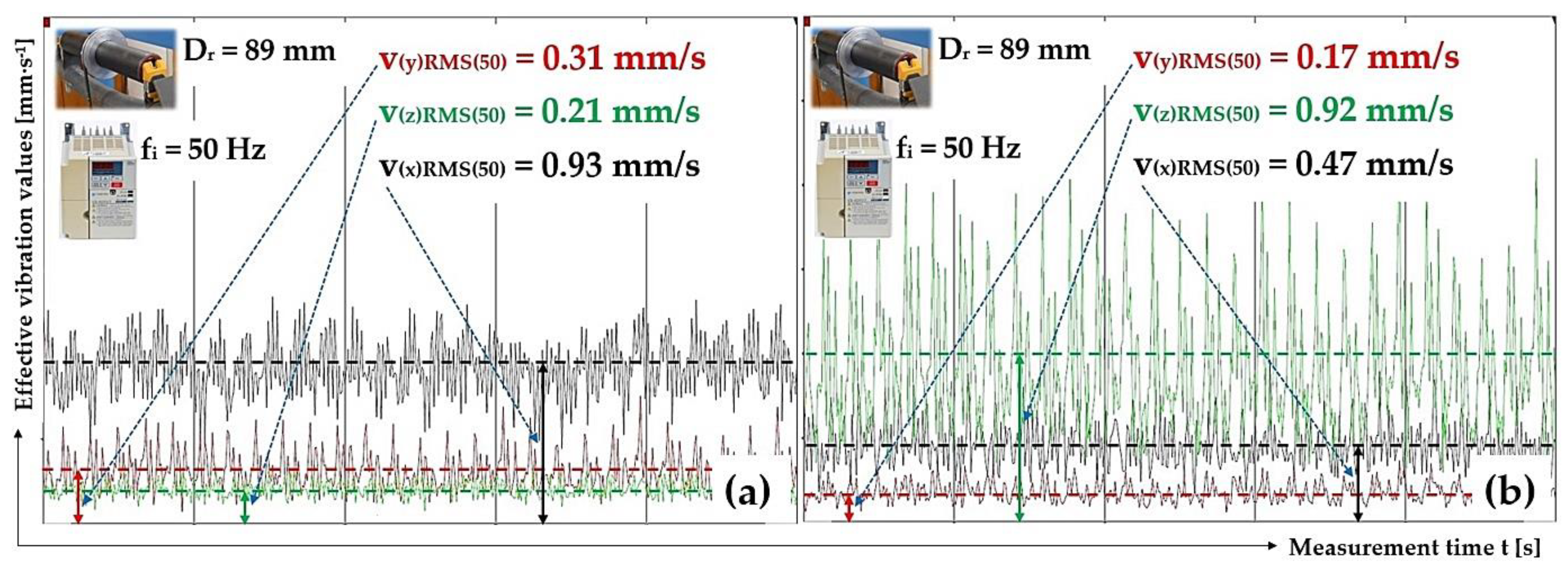
Figure 12.
Effective vibration values v(*)RMS(fi) [mm·s−1], ϕ89 mm plastic roller, the circumferential speed of the roller vr = 3.84 m·s−1, plastic trestle, (a) measuring point A, (b) measuring point B.
Figure 12.
Effective vibration values v(*)RMS(fi) [mm·s−1], ϕ89 mm plastic roller, the circumferential speed of the roller vr = 3.84 m·s−1, plastic trestle, (a) measuring point A, (b) measuring point B.
Figure 13.
Effective vibration values v(*)RMS(fi) [mm·s−1], ϕ89 mm steel roller, the circumferential speed of the roller vr = 3.84 m·s−1, plastic trestle, (a) measuring point A, (b) measuring point B.
Figure 13.
Effective vibration values v(*)RMS(fi) [mm·s−1], ϕ89 mm steel roller, the circumferential speed of the roller vr = 3.84 m·s−1, plastic trestle, (a) measuring point A, (b) measuring point B.
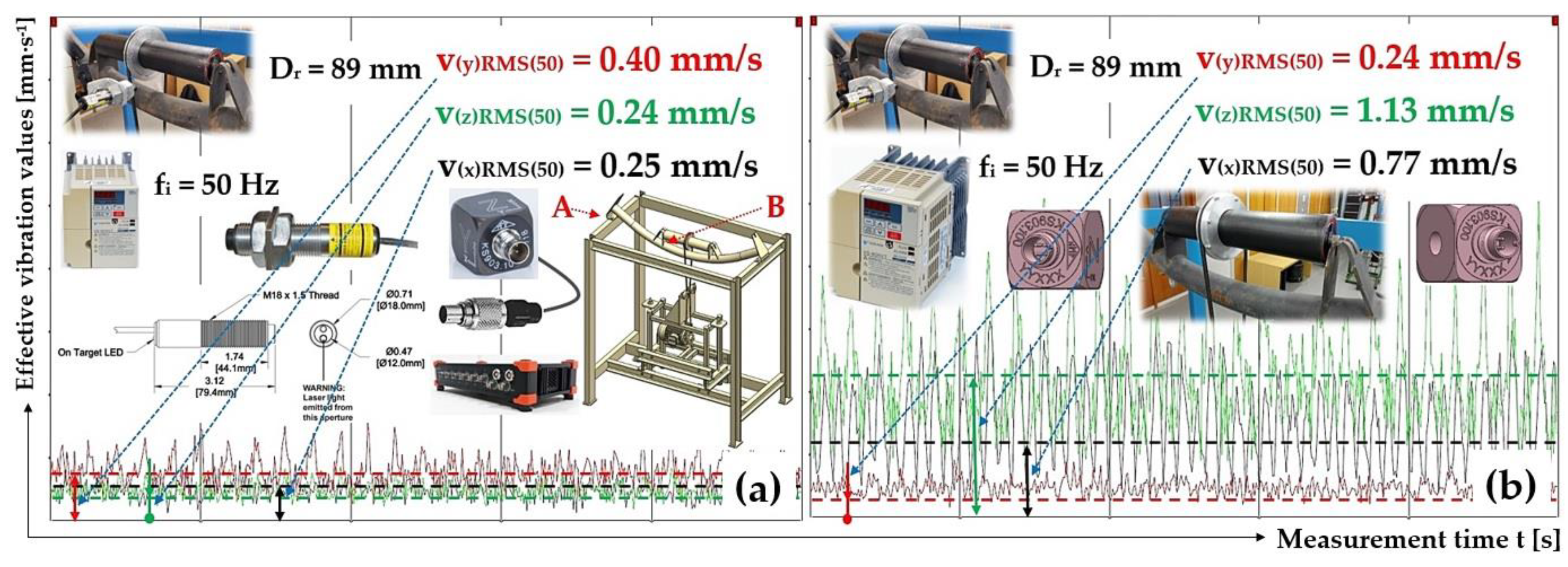
Figure 14.
Effective vibration values v(*)RMS(fi) [mm·s−1], ϕ89 mm plastic roller, the circumferential speed of the roller vr = 3.85 m·s−1, steel trestle, (a) measuring point A, (b) measuring point B.
Figure 14.
Effective vibration values v(*)RMS(fi) [mm·s−1], ϕ89 mm plastic roller, the circumferential speed of the roller vr = 3.85 m·s−1, steel trestle, (a) measuring point A, (b) measuring point B.
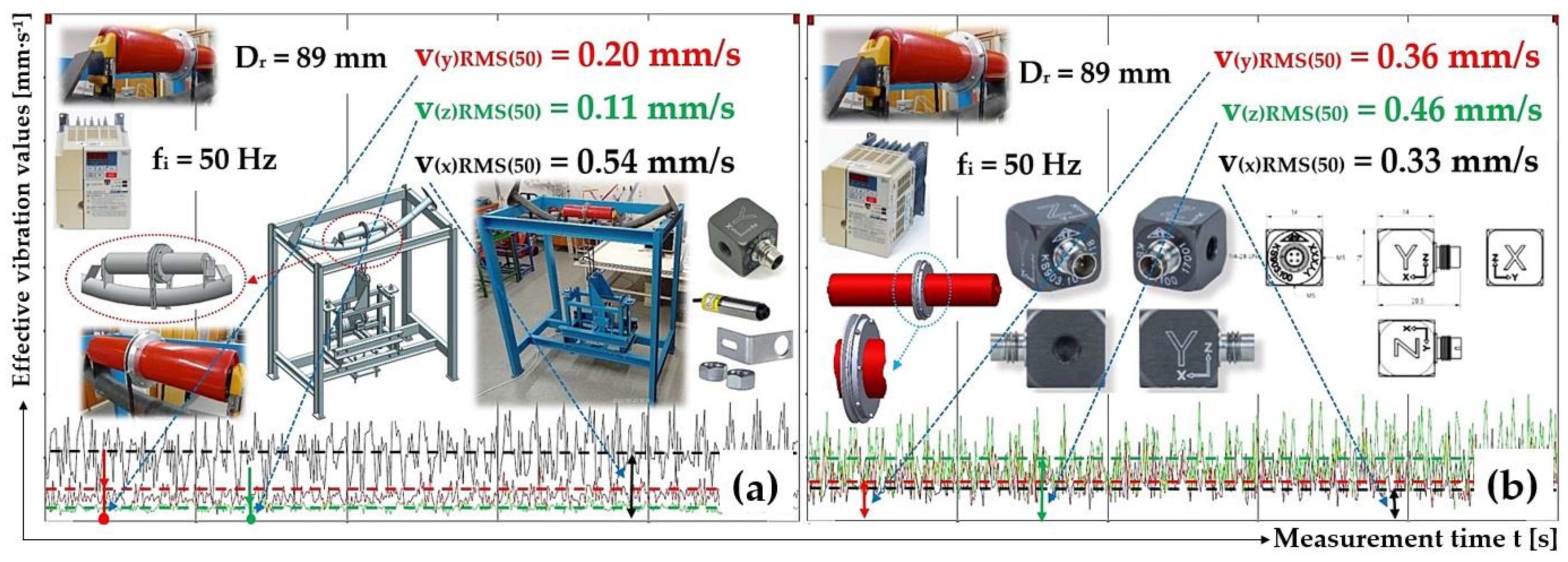
Figure 15.
Effective vibration values v(*)RMS(fi) [mm·s−1], ϕ89 mm steel roller, the circumferential speed of the roller vr = 3.84 m·s−1, steel trestle, (a) measuring point A, (b) measuring point B.
Figure 15.
Effective vibration values v(*)RMS(fi) [mm·s−1], ϕ89 mm steel roller, the circumferential speed of the roller vr = 3.84 m·s−1, steel trestle, (a) measuring point A, (b) measuring point B.
Figure 16.
The effective vibration values v
(*)RMS(fi) [mm·s
−1] of conveyor rollers with an 89 mm diameter, at revolutions of 825 min
−1. Measuring point as in
Figure 11 (
a) A, (
b) C, (
c) B, (
d) D.
Figure 16.
The effective vibration values v
(*)RMS(fi) [mm·s
−1] of conveyor rollers with an 89 mm diameter, at revolutions of 825 min
−1. Measuring point as in
Figure 11 (
a) A, (
b) C, (
c) B, (
d) D.
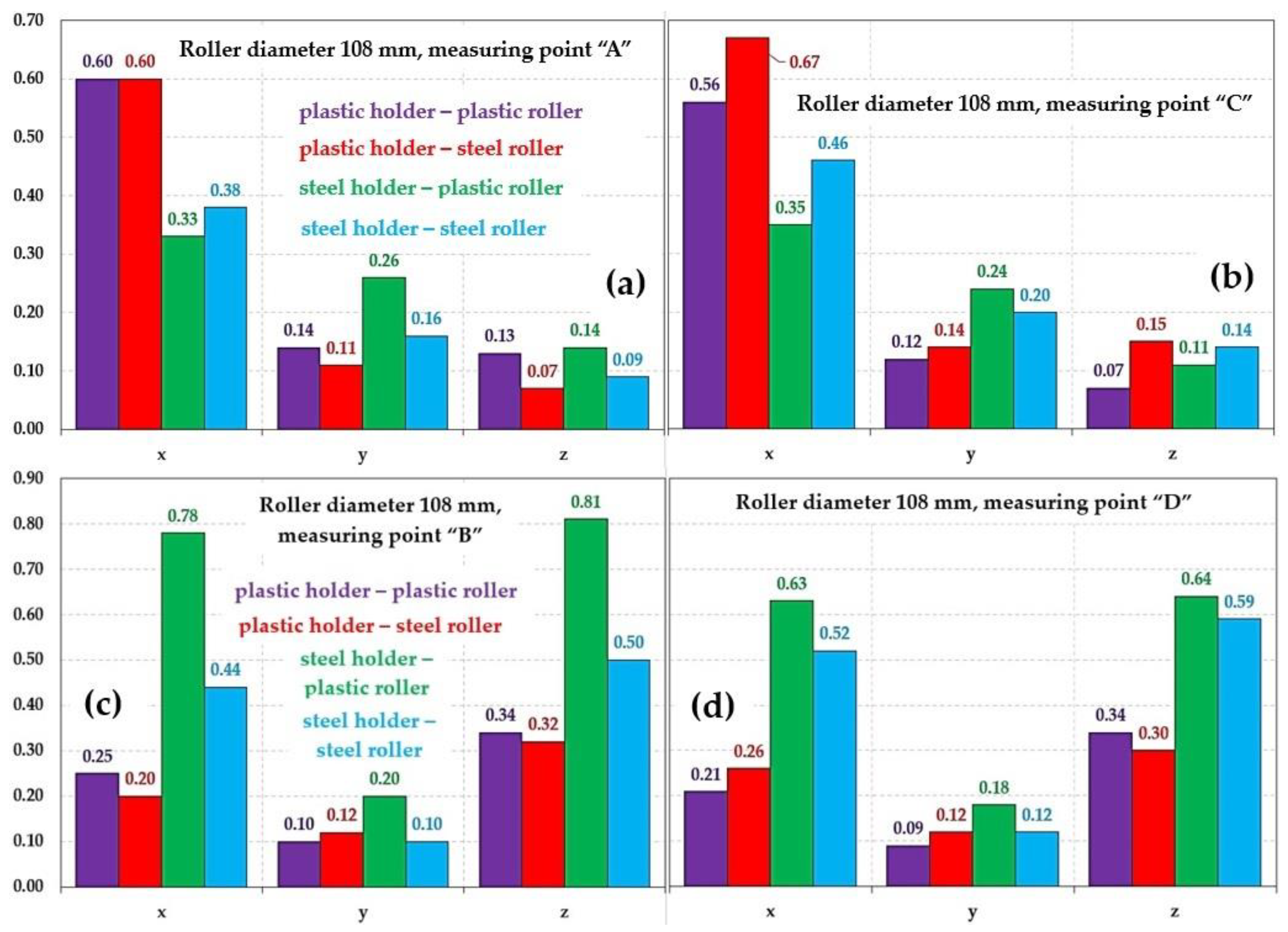
Figure 17.
The effective vibration values v
(*)RMS(fi) [mm·s
−1] of conveyor rollers with a 108 mm diameter, at revolutions of 442 min
−1. Measuring point as in
Figure 11 (
a) A, (
b) C, (
c) B, (
d) D.
Figure 17.
The effective vibration values v
(*)RMS(fi) [mm·s
−1] of conveyor rollers with a 108 mm diameter, at revolutions of 442 min
−1. Measuring point as in
Figure 11 (
a) A, (
b) C, (
c) B, (
d) D.
Figure 18.
The effective vibration values v
(*)RMS(fi) [mm·s
−1] of conveyor rollers with a 133 mm diameter, at revolutions 361 min
−1. Measuring point as in
Figure 11 (
a) A, (
b) C, (
c) B, (
d) D.
Figure 18.
The effective vibration values v
(*)RMS(fi) [mm·s
−1] of conveyor rollers with a 133 mm diameter, at revolutions 361 min
−1. Measuring point as in
Figure 11 (
a) A, (
b) C, (
c) B, (
d) D.
Figure 19.
The effective vibration values v
(*)RMS(fi) [mm·s
−1] of ϕ133 mm conveyor rollers at different revolutions when red line is plastic trestle, roller casing—steel, blue line is steel trestle, roller casing—steel, fialová line is plastic trestle, roller casing—plastic, and green line is steel trestle, roller casing—plastic. Measuring point as in
Figure 11 (
a) B, (
b) D, (
c) A, (
d) C.
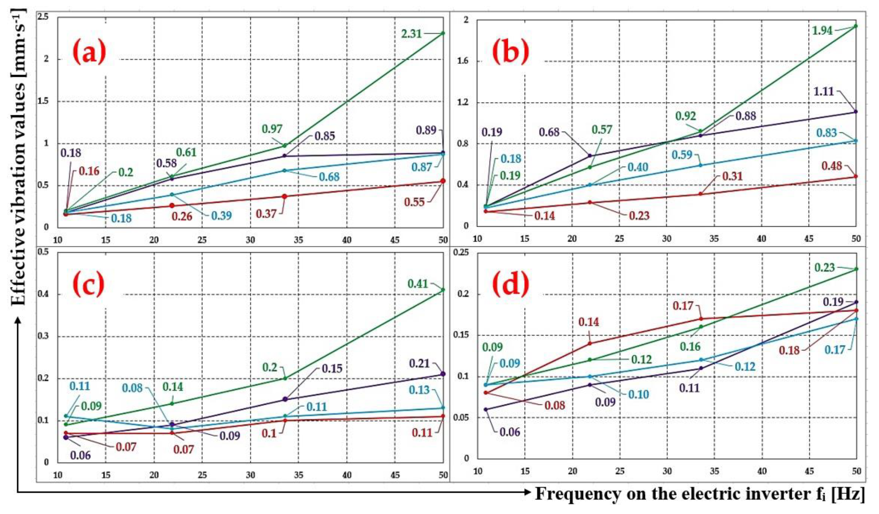
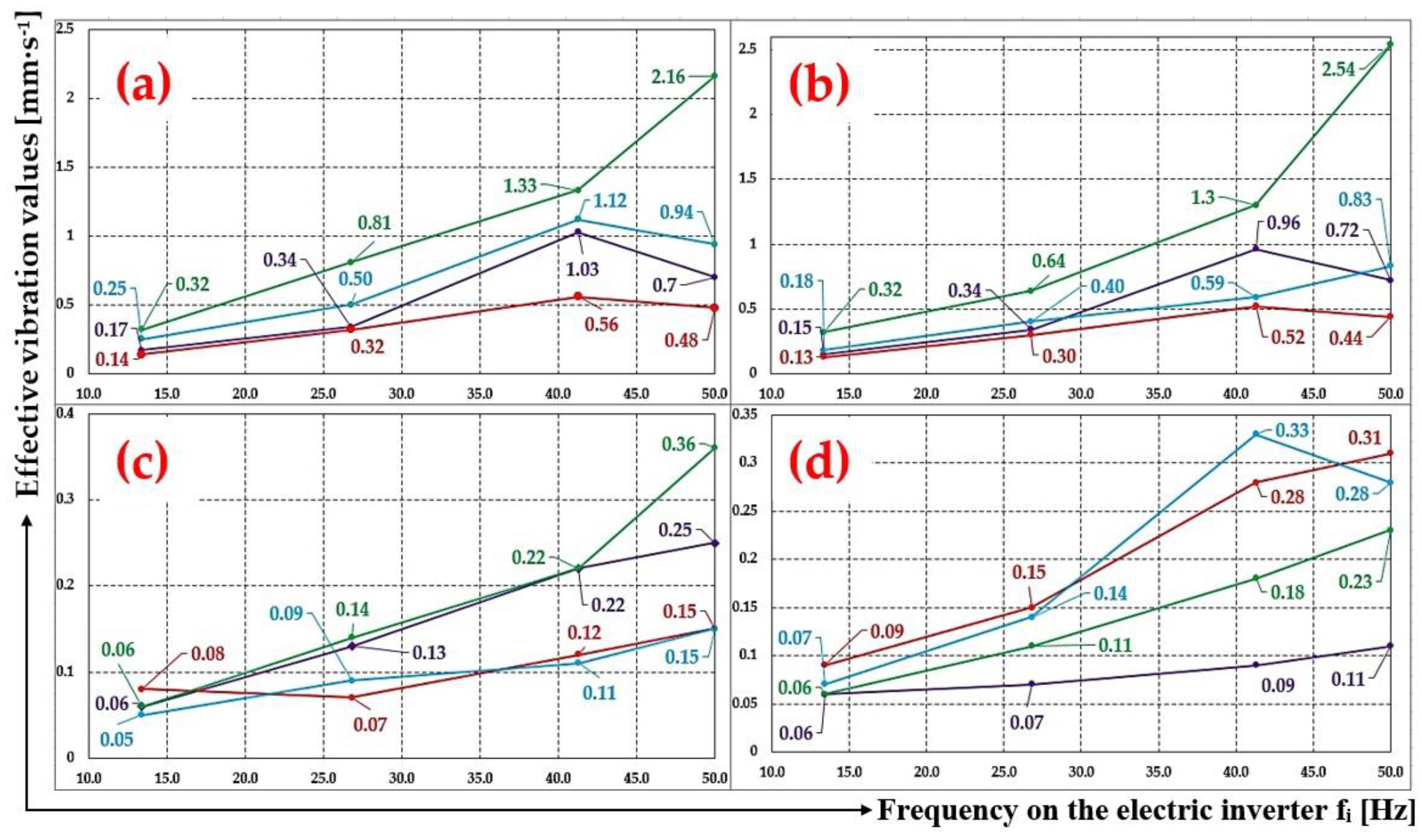
Figure 20.
The effective vibration values v
(*)RMS(fi) [mm·s
−1] of ϕ108 mm conveyor rollers at different revolutions when red line is plastic trestle, roller casing—steel, blue line is steel trestle, roller casing—steel, fialová line is plastic trestle, roller casing—plastic, and green line is steel trestle, roller casing—plastic. Measuring point as in
Figure 11 (
a) B, (
b) D, (
c) A, (
d) C.
Figure 21.
The effective vibration values v
(*)RMS(fi) [mm·s
−1] of ϕ89 mm conveyor rollers at different revolutions when red line is plastic trestle, roller casing—steel, blue line is steel trestle, roller casing—steel, fialová line is plastic trestle, roller casing—plastic, and green line is steel trestle, roller casing—plastic. Measuring point as in
Figure 11 (
a) B, (
b) D, (
c) A, (
d) C.
Table 1.
Calculated values of the rotational speed nr [min−1] of a conveyor roller with a given diameter Dr [m] for circumferential speed vr [m·s−1] of the conveyor roller casings.
Table 1.
Calculated values of the rotational speed nr [min−1] of a conveyor roller with a given diameter Dr [m] for circumferential speed vr [m·s−1] of the conveyor roller casings.
| Dr [mm] | 89 | 108 | 133 |
|---|
fi
[Hz] | vr
[m·s−1] | nr
[s−1] | nr
[min−1] | fi
[Hz] | vr
[m·s−1] | nr
[s−1] | nr
[min−1] | fi
[Hz] | vr
[m·s−1] | nr
[s−1] | nr
[min−1] |
|---|
| 50 | 3.58 | 12.81 | 768.7 | 50 | 4.35 | 12.82 | 769.2 | 50 | 5.35 | 12.80 | 768.3 |
| 34.9 | 2.5 | 8.94 | 536.5 | 41.2 | 3.58 | 10.55 | 633.1 | 33.4 | 3.58 | 10.41 | 624.7 |
| 17.4 | 1.25 | 4.47 | 268.2 | 28.8 | 2.5 | 7.37 | 442.1 | 23.4 | 2.5 | 5.98 | 359.0 |
| | | | | 14.4 | 1.25 | 3.68 | 221.0 | 11.7 | 1.25 | 2.99 | 179.5 |
Table 2.
Basic dimensions of the conveyor idler according to [
52].
Table 2.
Basic dimensions of the conveyor idler according to [
52].
| B | E | D = Dr | L | a | b | t | o | s | h | f | α | Weight |
|---|
| [mm] | [deg] | [kg] |
|---|
| 1200 | 1600 | 89, 108, 133 | 465 | 35 | 140 | 100 | 18 | 14 | 85 | 175 | 20 | 18.5 |
Table 3.
Roller axle placement—plastic trestle, measuring points A and B, roller casing—plastic, Dr = 89 mm.
Table 3.
Roller axle placement—plastic trestle, measuring points A and B, roller casing—plastic, Dr = 89 mm.
| fi | nr | vr | Measuring Point “A” | Measuring Point “B” |
|---|
| v(x)RMS(fi) | v(y)RMS(fi) | v(z)RMS(fi) | v(x)RMS(fi) | v(y)RMS(fi) | v(z)RMS(fi) |
|---|
| [Hz] | [min−1] | [m·s−1] | [mm·s−1] | [mm·s−1] |
|---|
| 50 | 825 | 3.84 | 0.93 1 | 0.31 1 | 0.21 1 | 0.47 2 | 0.17 2 | 0.92 2 |
| 32.5 | 536 | 2.50 | 0.23 | 0.21 | 0.10 | 0.52 | 0.14 | 0.62 |
| 16.2 | 268 | 1.25 | 0.14 | 0.10 | 0.07 | 0.14 | 0.08 | 0.22 |
Table 4.
Roller axle placement—plastic trestle, measuring points C and D, roller casing—plastic, Dr = 89 mm.
Table 4.
Roller axle placement—plastic trestle, measuring points C and D, roller casing—plastic, Dr = 89 mm.
| fi | nr | vr | Measuring Point “C” | Measuring Point “D” |
|---|
| v(x)RMS(fi) | v(y)RMS(fi) | v(z)RMS(fi) | v(x)RMS(fi) | v(y)RMS(fi) | v(z)RMS(fi) |
|---|
| [Hz] | [min−1] | [m·s−1] | [mm·s−1] | [mm·s−1] |
|---|
| 50 | 825 | 3.84 | 0.87 | 0.25 | 0.13 | 0.40 | 0.14 | 0.93 |
| 32.4 | 535 | 2.49 | 1.61 | 0.20 | 0.12 | 1.03 | 0.12 | 0.65 |
| 16.2 | 267 | 1.25 | 0.12 | 0.12 | 0.08 | 0.26 | 0.06 | 0.23 |
Table 5.
Roller axle placement—plastic trestle, measuring points A and B, roller casing—plastic, Dr = 108 mm.
Table 5.
Roller axle placement—plastic trestle, measuring points A and B, roller casing—plastic, Dr = 108 mm.
| fi | nr | vr | Measuring Point “A” | Measuring Point “B” |
|---|
| v(x)RMS(fi) | v(y)RMS(fi) | v(z)RMS(fi) | v(x)RMS(fi) | v(y)RMS(fi) | v(z)RMS(fi) |
|---|
| [Hz] | [min−1] | [m·s−1] | [mm·s−1] |
|---|
| 50 | 824 | 4.66 | 0.92 | 0.26 | 0.25 | 0.46 | 0.22 | 0.70 |
| 41.3 | 681 | 3.85 | 0.88 | 0.36 | 0.22 | 0.53 | 0.29 | 1.03 |
| 26.8 | 442 | 2.5 | 0.60 | 0.14 | 0.13 | 0.25 | 0.10 | 0.34 |
| 13.4 | 220 | 1.24 | 0.09 | 0.08 | 0.06 | 0.08 | 0.05 | 0.17 |
Table 6.
Roller axle placement—plastic trestle, measuring points C and D, roller casing—plastic, Dr = 108 mm.
Table 6.
Roller axle placement—plastic trestle, measuring points C and D, roller casing—plastic, Dr = 108 mm.
| fi | nr | vr | Measuring Point “C” | Measuring Point “D” |
|---|
| v(x)RMS(fi) | v(y)RMS(fi) | v(z)RMS(fi) | v(x)RMS(fi) | v(y)RMS(fi) | v(z)RMS(fi) |
|---|
| [Hz] | [min−1] | [m·s−1] | [mm·s−1] |
|---|
| 50 | 824 | 4.66 | 0.55 | 0.23 | 0.11 | 0.36 | 0.21 | 0.72 |
| 41.3 | 681 | 3.85 | 0.52 | 0.33 | 0.09 | 0.41 | 0.26 | 0.96 |
| 26.8 | 442 | 2.5 | 0.56 | 0.12 | 0.07 | 0.21 | 0.09 | 0.34 |
| 13.4 | 220 | 1.24 | 0.11 | 0.06 | 0.06 | 0.09 | 0.10 | 0.15 |
Table 7.
Roller axle placement—plastic trestle, measuring points A and B, roller casing—plastic, Dr = 133 mm.
Table 7.
Roller axle placement—plastic trestle, measuring points A and B, roller casing—plastic, Dr = 133 mm.
| fi | nr | vr | Measuring Point “A” | Measuring Point “B” |
|---|
| v(x)RMS(fi) | v(y)RMS(fi) | v(z)RMS(fi) | v(x)RMS(fi) | v(y)RMS(fi) | v(z)RMS(fi) |
|---|
| [Hz] | [min−1] | [m·s−1] | [mm·s−1] |
|---|
| 50 | 824 | 5.74 | 0.70 | 0.37 | 0.21 | 0.51 | 0.29 | 0.89 |
| 33.7 | 555 | 3.86 | 0.46 | 0.36 | 0.15 | 0.50 | 0.28 | 0.85 |
| 21.8 | 360 | 2.51 | 0.20 | 0.21 | 0.09 | 0.24 | 0.13 | 0.58 |
| 10.9 | 179 | 1.25 | 0.07 | 0.11 | 0.06 | 0.10 | 0.08 | 0.18 |
Table 8.
Roller axle placement—plastic trestle, measuring points C and D, roller casing—plastic, Dr = 133 mm.
Table 8.
Roller axle placement—plastic trestle, measuring points C and D, roller casing—plastic, Dr = 133 mm.
| fi | nr | vr | Measuring Point “C” | Measuring Point “D” |
|---|
| v(x)RMS(fi) | v(y)RMS(fi) | v(z)RMS(fi) | v(x)RMS(fi) | v(y)RMS(fi) | v(z)RMS(fi) |
|---|
| [Hz] | [min−1] | [m·s−1] | [mm·s−1] |
|---|
| 50 | 825 | 5.75 | 0.46 | 0.46 | 0.19 | 0.66 | 0.43 | 1.11 |
| 33.7 | 555 | 3.86 | 0.73 | 0.35 | 0.11 | 0.55 | 0.34 | 0.88 |
| 21.8 | 360 | 2.50 | 0.18 | 0.20 | 0.09 | 0.27 | 0.13 | 0.68 |
| 10.9 | 179 | 1.25 | 0.08 | 0.09 | 0.06 | 0.10 | 0.08 | 0.19 |
Table 9.
Roller axles placement—plastic trestle, measuring points A and B, roller casing—steel, Dr = 89 mm.
Table 9.
Roller axles placement—plastic trestle, measuring points A and B, roller casing—steel, Dr = 89 mm.
| fi | nr | vr | Measuring Point “A” | Measuring Point “B” |
|---|
| v(x)RMS(fi) | v(y)RMS(fi) | v(z)RMS(fi) | v(x)RMS(fi) | v(y)RMS(fi) | v(z)RMS(fi) |
|---|
| [Hz] | [min−1] | [m·s−1] | [mm·s−1] |
|---|
| 50 | 823 | 3.84 | 0.54 1 | 0.20 1 | 0.11 1 | 0.33 2 | 0.36 2 | 0.46 2 |
| 32.3 | 533 | 2.48 | 1.93 | 0.46 | 0.16 | 1.32 | 0.60 | 0.56 |
| 16.1 | 266 | 1.24 | 0.22 | 0.10 | 0.08 | 0.24 | 0.12 | 0.21 |
Table 10.
Roller axles placement—plastic trestle, measuring points C and D, roller casing—steel, Dr = 89 mm.
Table 10.
Roller axles placement—plastic trestle, measuring points C and D, roller casing—steel, Dr = 89 mm.
| fi | nr | vr | Measuring Point “C” | Measuring Point “D” |
|---|
| v(x)RMS(fi) | v(y)RMS(fi) | v(z)RMS(fi) | v(x)RMS(fi) | v(y)RMS(fi) | v(z)RMS(fi) |
|---|
| [Hz] | [min−1] | [m·s−1] | [mm·s−1] |
|---|
| 50 | 823 | 3.84 | 1.09 | 0.18 | 0.26 | 0.43 | 0.28 | 0.46 |
| 32.3 | 533 | 2.48 | 0.81 | 0.51 | 0.22 | 0.70 | 0.52 | 0.52 |
| 16.12 | 266 | 1.24 | 0.17 | 0.10 | 0.09 | 0.11 | 0.07 | 0.18 |
Table 11.
Roller axles placement—plastic trestle, measuring points A and B, roller casing—steel, Dr = 108 mm.
Table 11.
Roller axles placement—plastic trestle, measuring points A and B, roller casing—steel, Dr = 108 mm.
| fi | nr | vr | Measuring Point “A” | Measuring Point “B” |
|---|
| v(x)RMS(fi) | v(y)RMS(fi) | v(z)RMS(fi) | v(x)RMS(fi) | v(y)RMS(fi) | v(z)RMS(fi) |
|---|
| [Hz] | [min−1] | [m·s−1] | [mm·s−1] |
|---|
| 50 | 826 | 4.67 | 0.75 | 0.24 | 0.15 | 0.39 | 0.19 | 0.48 |
| 41.4 | 682 | 3.86 | 0.36 | 0.31 | 0.12 | 0.32 | 0.18 | 0.56 |
| 26.84 | 442 | 2.5 | 0.60 | 0.11 | 0.07 | 0.20 | 0.12 | 0.32 |
| 13.36 | 220 | 1.25 | 0.12 | 0.08 | 0.08 | 0.10 | 0.08 | 0.14 |
Table 12.
Roller axles placement—plastic trestle, measuring points C and D, roller casing—steel, Dr = 108 mm.
Table 12.
Roller axles placement—plastic trestle, measuring points C and D, roller casing—steel, Dr = 108 mm.
| fi | nr | vr | Measuring Point “C” | Measuring Point “D” |
|---|
| v(x)RMS(fi) | v(y)RMS(fi) | v(z)RMS(fi) | v(x)RMS(fi) | v(y)RMS(fi) | v(z)RMS(fi) |
|---|
| [Hz] | [min−1] | [m·s−1] | [mm·s−1] |
|---|
| 50 | 826 | 4.67 | 1.40 | 0.20 | 0.31 | 0.38 | 0.19 | 0.44 |
| 41.34 | 681 | 3.85 | 1.27 | 0.25 | 0.28 | 0.61 | 0.19 | 0.52 |
| 26.85 | 443 | 2.5 | 0.67 | 0.14 | 0.15 | 0.26 | 0.12 | 0.30 |
| 13.37 | 220 | 1.25 | 0.11 | 0.12 | 0.09 | 0.08 | 0.07 | 0.13 |
Table 13.
Roller axles placement—plastic trestle, measuring points A and B, roller casing—steel, Dr = 133 mm.
Table 13.
Roller axles placement—plastic trestle, measuring points A and B, roller casing—steel, Dr = 133 mm.
| fi | nr | vr | Measuring Point “A” | Measuring Point “B” |
|---|
| v(x)RMS(fi) | v(y)RMS(fi) | v(z)RMS(fi) | v(x)RMS(fi) | v(y)RMS(fi) | v(z)RMS(fi) |
|---|
| [Hz] | [min−1] | [m·s−1] | [mm·s−1] |
|---|
| 50 | 825 | 5.75 | 0.47 | 0.24 | 0.11 | 0.35 | 0.24 | 0.55 |
| 33.64 | 554 | 3.86 | 0.64 | 0.17 | 0.10 | 0.48 | 0.18 | 0.37 |
| 21.92 | 361 | 2.52 | 0.23 | 0.12 | 0.07 | 0.21 | 0.13 | 0.26 |
| 10.89 | 179 | 1.25 | 0.19 | 0.09 | 0.07 | 0.14 | 0.09 | 0.16 |
Table 14.
Roller axles placement—plastic trestle, measuring points C and D, roller casing—steel, Dr = 133 mm.
Table 14.
Roller axles placement—plastic trestle, measuring points C and D, roller casing—steel, Dr = 133 mm.
| fi | nr | vr | Measuring Point “C” | Measuring Point “D” |
|---|
| v(x)RMS(fi) | v(y)RMS(fi) | v(z)RMS(fi) | v(x)RMS(fi) | v(y)RMS(fi) | v(z)RMS(fi) |
|---|
| [Hz] | [min−1] | [m·s−1] | [mm·s−1] |
|---|
| 50 | 825 | 5.75 | 0.49 | 0.24 | 0.18 | 0.27 | 0.19 | 0.48 |
| 33.67 | 555 | 3.87 | 0.32 | 0.18 | 0.17 | 0.30 | 0.14 | 0.31 |
| 21.87 | 361 | 2.51 | 0.21 | 0.11 | 0.14 | 0.13 | 0.09 | 0.23 |
| 10.89 | 179 | 1.25 | 0.11 | 0.07 | 0.08 | 0.08 | 0.06 | 0.14 |
Table 15.
Roller axles placement—steel trestle, measuring points A and B, roller casing—plastic, Dr = 89 mm.
Table 15.
Roller axles placement—steel trestle, measuring points A and B, roller casing—plastic, Dr = 89 mm.
| fi | nr | vr | Measuring Point “A” | Measuring Point “B” |
|---|
| v(x)RMS(fi) | v(y)RMS(fi) | v(z)RMS(fi) | v(x)RMS(fi) | v(y)RMS(fi) | v(z)RMS(fi) |
|---|
| [Hz] | [min−1] | [m·s−1] | [mm·s−1] | [mm·s−1] |
|---|
| 50 | 824 | 3.84 | 0.25 1 | 0.40 1 | 0.24 1 | 0.77 2 | 0.24 2 | 1.13 2 |
| 32.33 | 533 | 2.48 | 0.92 | 0.25 | 0.17 | 1.02 | 0.14 | 0.81 |
| 16.14 | 266 | 1.24 | 0.09 | 0.14 | 0.15 | 0.28 | 0.13 | 0.32 |
Table 16.
Roller axles placement—steel trestle, measuring points C and D roller casing—plastic, Dr = 89 mm.
Table 16.
Roller axles placement—steel trestle, measuring points C and D roller casing—plastic, Dr = 89 mm.
| fi | nr | vr | Measuring Point “C” | Measuring Point “D” |
|---|
| v(x)RMS(fi) | v(y)RMS(fi) | v(z)RMS(fi) | v(x)RMS(fi) | v(y)RMS(fi) | v(z)RMS(fi) |
|---|
| [Hz] | [min−1] | [m·s−1] | [mm·s−1] |
|---|
| 50 | 826 | 3.85 | 0.28 | 0.37 | 0.15 | 0.77 | 0.27 | 1.04 |
| 32.35 | 533 | 2.48 | 0.26 | 0.28 | 0.12 | 0.89 | 0.17 | 0.79 |
| 16.15 | 266 | 1.24 | 0.11 | 0.17 | 0.13 | 0.31 | 0.14 | 0.33 |
Table 17.
Roller axles placement—steel trestle, measuring points A and B roller casing—plastic, Dr = 108 mm.
Table 17.
Roller axles placement—steel trestle, measuring points A and B roller casing—plastic, Dr = 108 mm.
| fi | nr | vr | Measuring Point “A” | Measuring Point “B” |
|---|
| v(x)RMS(fi) | v(y)RMS(fi) | v(z)RMS(fi) | v(x)RMS(fi) | v(y)RMS(fi) | v(z)RMS(fi) |
|---|
| [Hz] | [min−1] | [m·s−1] | [mm·s−1] |
|---|
| 50 | 825 | 4.66 | 0.44 | 0.53 | 0.36 | 0.66 | 0.32 | 2.16 |
| 41.24 | 680 | 3.84 | 0.28 | 0.41 | 0.22 | 0.76 | 0.32 | 1.33 |
| 26.73 | 441 | 2.50 | 0.33 | 0.26 | 0.14 | 0.78 | 0.20 | 0.81 |
| 13.34 | 220 | 1.24 | 0.08 | 0.13 | 0.06 | 0.17 | 0.10 | 0.32 |
Table 18.
Roller axles placement—steel trestle, measuring points C and D roller casing—plastic, Dr = 108 mm.
Table 18.
Roller axles placement—steel trestle, measuring points C and D roller casing—plastic, Dr = 108 mm.
| fi | nr | vr | Measuring Point “C” | Measuring Point “D” |
|---|
| v(x)RMS(fi) | v(y)RMS(fi) | v(z)RMS(fi) | v(x)RMS(fi) | v(y)RMS(fi) | v(z)RMS(fi) |
|---|
| [Hz] | [min−1] | [m·s−1] | [mm·s−1] |
|---|
| 50 | 823 | 4.65 | 0.58 | 0.86 | 0.23 | 0.61 | 0.45 | 2.54 |
| 41.29 | 681 | 3.85 | 0.66 | 0.48 | 0.18 | 0.76 | 0.40 | 1.30 |
| 26.68 | 440 | 2.49 | 0.35 | 0.24 | 0.11 | 0.63 | 0.18 | 0.64 |
| 13.35 | 220 | 1.24 | 0.08 | 0.13 | 0.06 | 0.14 | 0.09 | 0.32 |
Table 19.
Roller axles placement—steel trestle, measuring points A and B roller casing—plastic, Dr = 133 mm.
Table 19.
Roller axles placement—steel trestle, measuring points A and B roller casing—plastic, Dr = 133 mm.
| fi | nr | vr | Measuring Point “A” | Measuring Point “B” |
|---|
| v(x)RMS(fi) | v(y)RMS(fi) | v(z)RMS(fi) | v(x)RMS(fi) | v(y)RMS(fi) | v(z)RMS(fi) |
|---|
| [Hz] | [min−1] | [m·s−1] | [mm·s−1] |
|---|
| 50 | 825 | 5.75 | 0.44 | 0.66 | 0.41 | 0.76 | 0.41 | 2.31 |
| 33.48 | 552 | 3.84 | 0.46 | 0.43 | 0.20 | 0.57 | 0.38 | 0.97 |
| 21.83 | 360 | 2.51 | 0.13 | 0.25 | 0.14 | 0.35 | 0.21 | 0.61 |
| 10.84 | 179 | 1.24 | 0.08 | 0.12 | 0.09 | 0.16 | 0.09 | 0.20 |
Table 20.
Roller axles placement—steel trestle, measuring points C and D roller casing—plastic, Dr = 133 mm.
Table 20.
Roller axles placement—steel trestle, measuring points C and D roller casing—plastic, Dr = 133 mm.
| fi | nr | vr | Measuring Point “C” | Measuring Point “D” |
|---|
| v(x)RMS(fi) | v(y)RMS(fi) | v(z)RMS(fi) | v(x)RMS(fi) | v(y)RMS(fi) | v(z)RMS(fi) |
|---|
| [Hz] | [min−1] | [m·s−1] | [mm·s−1] |
|---|
| 50 | 824 | 5.74 | 0.69 | 0.68 | 0.23 | 0.95 | 0.39 | 1.94 |
| 33.56 | 553 | 3.85 | 0.49 | 0.38 | 0.16 | 0.63 | 0.27 | 0.92 |
| 21.84 | 360 | 2.51 | 0.18 | 0.23 | 0.12 | 0.38 | 0.18 | 0.57 |
| 10.84 | 179 | 1.24 | 0.11 | 0.15 | 0.09 | 0.21 | 0.10 | 0.19 |
Table 21.
Roller axles placement—steel trestle, measuring points A and B roller casing—steel, Dr = 89 mm.
Table 21.
Roller axles placement—steel trestle, measuring points A and B roller casing—steel, Dr = 89 mm.
| fi | nr | vr | Measuring Point “A” | Measuring Point “B” |
|---|
| v(x)RMS(fi) | v(y)RMS(fi) | v(z)RMS(fi) | v(x)RMS(fi) | v(y)RMS(fi) | v(z)RMS(fi) |
|---|
| [Hz] | [min−1] | [m·s−1] | [mm·s−1] | [mm·s−1] |
|---|
| 50 | 825 | 3.84 | 0.46 1 | 0.38 1 | 0.17 1 | 0.82 2 | 0.20 2 | 1.23 2 |
| 32.4 | 534 | 2.49 | 0.92 | 0.57 | 0.13 | 0.96 | 0.57 | 0.80 |
| 16.17 | 267 | 1.24 | 0.09 | 0.11 | 0.07 | 0.21 | 0.07 | 0.24 |
Table 22.
Roller axles placement—steel trestle, measuring points C and D roller casing—steel, Dr = 89 mm.
Table 22.
Roller axles placement—steel trestle, measuring points C and D roller casing—steel, Dr = 89 mm.
| fi | nr | vr | Measuring Point “C” | Measuring Point “D” |
|---|
| v(x)RMS(fi) | v(y)RMS(fi) | v(z)RMS(fi) | v(x)RMS(fi) | v(y)RMS(fi) | v(z)RMS(fi) |
|---|
| [Hz] | [min−1] | [m·s−1] | [mm·s−1] |
|---|
| 50 | 826 | 3.85 | 0.92 | 0.36 | 0.26 | 0.79 | 0.18 | 1.15 |
| 32.4 | 534 | 2.49 | 0.92 | 0.57 | 0.13 | 0.96 | 0.57 | 0.80 |
| 16.17 | 267 | 1.24 | 0.09 | 0.11 | 0.07 | 0.21 | 0.07 | 0.24 |
Table 23.
Roller axles placement—steel trestle, measuring points A and B roller casing—steel, Dr = 108 mm.
Table 23.
Roller axles placement—steel trestle, measuring points A and B roller casing—steel, Dr = 108 mm.
| fi | nr | vr | Measuring Point “A” | Measuring Point “B” |
|---|
| v(x)RMS(fi) | v(y)RMS(fi) | v(z)RMS(fi) | v(x)RMS(fi) | v(y)RMS(fi) | v(z)RMS(fi) |
|---|
| [Hz] | [min−1] | [m·s−1] | [mm·s−1] |
|---|
| 50 | 823 | 4.65 | 0.61 | 0.35 | 0.15 | 0.83 | 0.24 | 0.94 |
| 41.25 | 680 | 3.85 | 0.35 | 0.36 | 0.11 | 0.90 | 0.24 | 1.12 |
| 26.73 | 441 | 2.49 | 0.38 | 0.16 | 0.09 | 0.44 | 0.10 | 0.50 |
| 13.30 | 219 | 1.24 | 0.06 | 0.10 | 0.05 | 0.14 | 0.08 | 0.25 |
Table 24.
Roller axles placement—steel trestle, measuring points C and D roller casing—steel, Dr = 108 mm.
Table 24.
Roller axles placement—steel trestle, measuring points C and D roller casing—steel, Dr = 108 mm.
| fi | nr | vr | Measuring Point “C” | Measuring Point “D” |
|---|
| v(x)RMS(fi) | v(y)RMS(fi) | v(z)RMS(fi) | v(x)RMS(fi) | v(y)RMS(fi) | v(z)RMS(fi) |
|---|
| [Hz] | [min−1] | [m·s−1] | [mm·s−1] |
|---|
| 50 | 823 | 4.66 | 1.14 | 0.30 | 0.28 | 0.99 | 0.24 | 0.84 |
| 41.20 | 679 | 3.84 | 1.19 | 0.40 | 0.33 | 1.03 | 0.33 | 1.10 |
| 26.73 | 441 | 2.49 | 0.46 | 0.20 | 0.14 | 0.52 | 0.12 | 0.59 |
| 13.32 | 220 | 1.24 | 0.07 | 0.10 | 0.07 | 0.13 | 0.07 | 0.21 |
Table 25.
Roller axles placement—steel trestle, measuring points A and B roller casing—steel, Dr = 133 mm.
Table 25.
Roller axles placement—steel trestle, measuring points A and B roller casing—steel, Dr = 133 mm.
| fi | nr | vr | Measuring Point “A” | Measuring Point “B” |
|---|
| v(x)RMS(fi) | v(y)RMS(fi) | v(z)RMS(fi) | v(x)RMS(fi) | v(y)RMS(fi) | v(z)RMS(fi) |
|---|
| [Hz] | [min−1] | [m·s−1] | [mm·s−1] |
|---|
| 50 | 826 | 5.75 | 0.29 | 0.29 | 0.13 | 0.46 | 0.18 | 0.87 |
| 33.66 | 555 | 3.86 | 0.43 | 0.21 | 0.11 | 0.49 | 0.14 | 0.68 |
| 21.89 | 361 | 2.51 | 0.14 | 0.13 | 0.08 | 0.26 | 0.09 | 0.39 |
| 10.87 | 179 | 1.25 | 0.10 | 0.06 | 0.11 | 0.14 | 0.09 | 0.18 |
Table 26.
Roller axles placement—steel trestle, measuring points C and D roller casing—steel, Dr = 133 mm.
Table 26.
Roller axles placement—steel trestle, measuring points C and D roller casing—steel, Dr = 133 mm.
| fi | nr | vr | Measuring Point “C” | Measuring Point “D” |
|---|
| v(x)RMS(fi) | v(y)RMS(fi) | v(z)RMS(fi) | v(x)RMS(fi) | v(y)RMS(fi) | v(z)RMS(fi) |
|---|
| [Hz] | [min−1] | [m·s−1] | [mm·s−1] |
|---|
| 50 | 824 | 5.74 | 0.33 | 0.30 | 0.17 | 0.42 | 0.20 | 0.83 |
| 33.59 | 554 | 3.86 | 0.26 | 0.21 | 0.12 | 0.33 | 0.14 | 0.59 |
| 21.87 | 361 | 2.51 | 0.23 | 0.15 | 0.10 | 0.23 | 0.10 | 0.40 |
| 10.87 | 179 | 1.25 | 0.10 | 0.14 | 0.09 | 0.11 | 0.09 | 0.18 |


