Article

Natural Field Airborne Electromagnetics—History of Development and Current Exploration Capabilities

Expert Geophysics Limited, Aurora, ON L4G 1G2, Canada
*
Author to whom correspondence should be addressed.
Minerals 2022, 12(5), 583; https://doi.org/10.3390/min12050583
Submission received: 7 April 2022 / Revised: 28 April 2022 / Accepted: 30 April 2022 / Published: 5 May 2022
(This article belongs to the Special Issue Electromagnetic Exploration: Theory, Methods and Applications)

Abstract

:
The mineral resources exploration industry continuously expands the efficiency requirements for geophysical technologies. Due to their relatively inexpensive nature, coupled with the ability to rapidly acquire data over large areas, airborne electromagnetic technologies have been used for decades in subsurface exploration. Limitations on the depth of investigation of airborne platforms with controlled primary field sources is the main obstacle for using these systems in many geoelectrical conditions and geographical terrains. In addition, systems based on the time-domain principle are limited in applications requiring differentiations in a high resistivity range of the mapping parameter and suffer from parasitic electromagnetic non inductive natural effects in specific near surface conditions. Methods exploiting natural electromagnetic fields in the audio frequency range significantly increase depth of investigation and sensitivity to a wide range of resistivity contrasts including in the range of thousands of ohm-ms. A brief history of the development of the natural field airborne technology is provided accompanied by a comparison of the systems technical specifications. Field examples from the latest development in the airborne electromagnetic natural fields’ domain, MobileMT, demonstrate its exploration capabilities in both conductive and resistive environments, sensitivity to any direction of geoelectrical boundary, and detectability of near-surface discrete targets along with deeper structures.

1. Introduction

Historically, airborne electromagnetic induction methods (AEM) with controlled primary field sources have been given attention by many specialists. Frequency-domain systems (FDEM), which make use of a harmonic magnetic field source, were under constant development and in active use during the last century [1]. After many decades of use, the frequency-domain method, despite being sensitive over a wide range of resistivities, is limited in depth of investigation. Time-domain systems (TDEM) excited by a step pulse have replaced frequency-domain systems for the majority of exploration applications due to a greater depth of investigation, in general [2,3,4]. Many improvements to airborne time-domain systems were achieved during the last 20 years. However, several limitations persist which restrict the use of the time-domain AEM principle, including:
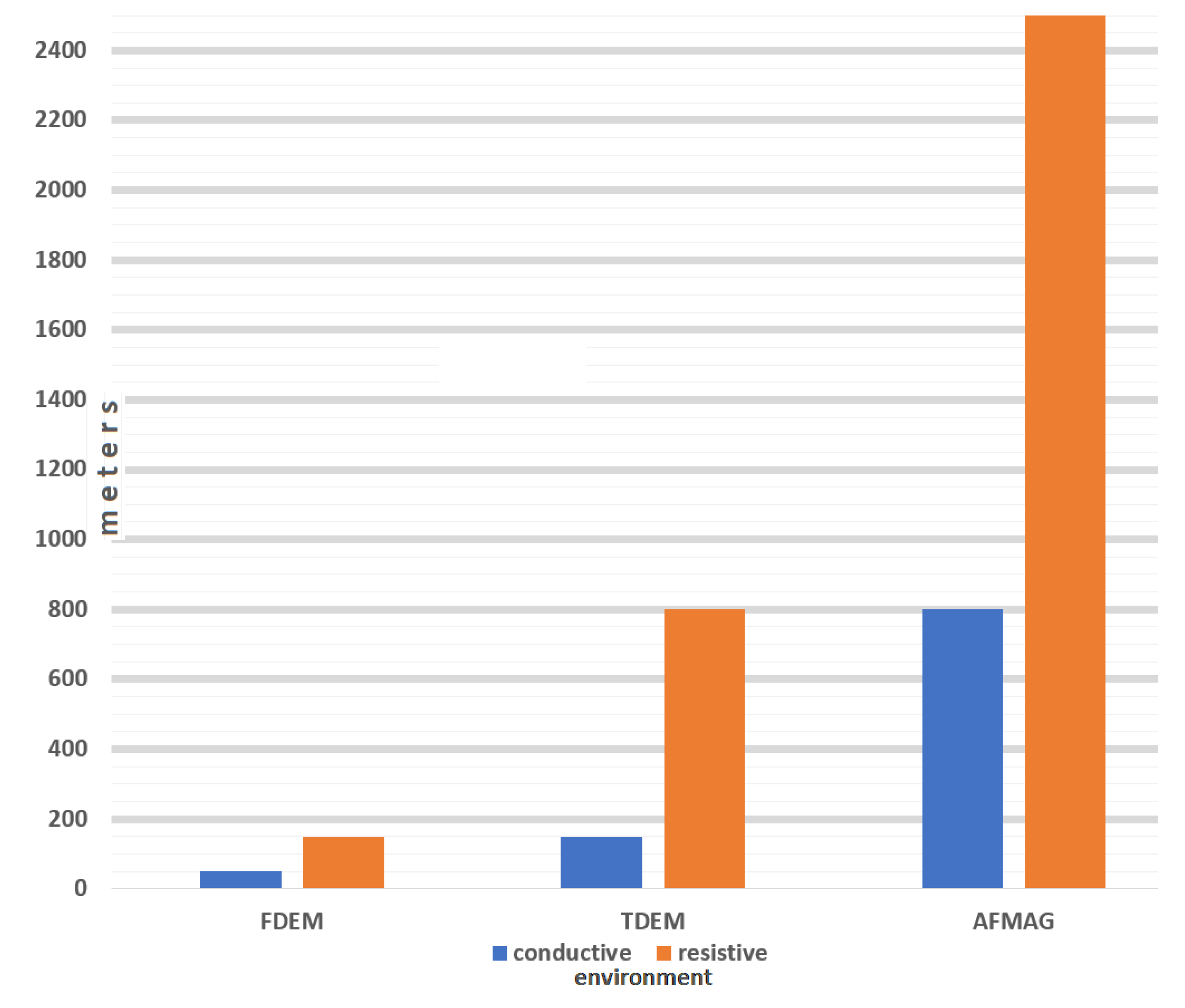
  • the depth of investigation does not always meet exploration requirements, especially in conductive environments;
  • the measured signal and depth of investigation are highly dependent on the transmitter height, tilt, and geometry. The dependance creates difficulties and restrictions for surveys in rugged terrain;
  • there are challenges in getting a measurable response in resistive terrain and with subtle resistivity contrasts; and there are parasitic IP and SPM effects on measured induction under specific near surface conditions [5].
Methods which exploit natural electromagnetic fields (magnetotelluric and magnetovariational, AFMAG) are capable of overcoming the limitations of airborne systems with controlled primary field sources. Comparative estimation of depth of investigation of different airborne electromagnetic principles is presented in Figure 1.
In this paper, we describe a brief history of the development of airborne natural field methods, specifically discussing the main technical solutions that have become commercially available, with a focus on the MobileMT airborne system, the latest development in the field of passive source methods. MobileMT field examples from different geoelectrical conditions and for different exploration objectives are presented in this paper.

2. Review of the Development of the Airborne Natural Electromagnetic Fields Method and the MobileMT Technology

The initial Tikhonov-Cagniard method described in 1950-53 [6,7] and known as MT (magnetotelluric) sounding, determines the electrical conductivity of the subsurface through simultaneous measurements of the horizontal components of the natural electric and magnetic fields at a single point at the surface as expressed by the impedance operator Z [8]. Cagniard [7], in particular, defines the magnetotelluric method as a method which “involves the comparison, preferably at one and the same place, of the horizontal components of the magnetic and electric fields associated with the flow of telluric currents.” Another approach in the field of modern magnetotellurics is called MV (magnetovariational) sounding and is restricted to measurements of the magnetic field components [9,10]. The traditional scheme of the MV sounding is based on the linear relationship between the vertical and horizontal magnetic field components and is expressed by the tipper operator, Wz [11]. One of the main differences between the interrelated approaches is in output characteristics:
-
the MT sounding characteristics are the impedance tensor described by the relationships between magnetic and electric field components, and apparent resistivities, derived from the impedance tensor, corresponding to different frequencies;
-
whereas the MV sounding characteristic is the ‘tipper’, which describes the relationship between the vertical and horizontal components of the magnetic field.
One of the significant problems with the “impedance MT” method is the strong distorting influence of near-surface (which are out of the depth range of investigation) galvanic effects resulting in systematic (static) shift of the apparent resistivity curves for each sounding station. The MV tipper operator (Wz) is free of the effect of galvanic distortions [9].
Further development of the MT and MV approaches is related to the combined analysis of synchronous transfer operators, telluric, T and magnetovariational, M. The T-M operators connect the horizontal components of electric and magnetic fields simultaneously measured in two different places—moving ‘field’ and stationary ‘reference’ [11]. The MV method based on the horizontal M operator has a very important advantage over the tipper Wz operator: local MV(M) anomalies over targets with comparatively low resistivity are clear and distinct whereas tipper MV(Wz) amplitudes are small especially over the targets’ central parts [11].
The MT, MV ground electromagnetic sounding schemes, and their combination, serve as a basis for the development of airborne electromagnetic methods.

2.1. Original AFMAG Method

The first period of theoretical development and practical usage of AFMAG (audio-frequency magnetic technique), as an inductive electromagnetic method exploited audio frequency natural magnetic fields and is described in a series of publications from the period of 1958–1968 [12,13,14,15]. One of the main reasons of the development was the potential to provide significant depth information without exploiting technically limited primary field, controlled sources. The airborne AFMAG system was commercially used by McPhar Geophysics Limited in the 1960s and early 1970s [16], but the company shifted their commercial focus to radiometry, and thus the electromagnetic methods development was terminated [17]. The basic technical parameters of the system are provided in Table 1.
The AFMAG method is aimed at measuring the electromagnetic induction of currents in the geological environment caused by naturally occurring alternating magnetic fields. In the natural field electromagnetic methods domain, only AFMAG became mobile, with continuous measurements in motion [18].
Separation of the time-variance from the space-variance (correlated with the time-varying natural component and geologic features) of the fields is the critical problem of the method. A comparator measuring technique became, at that time, a solution for the initial AFMAG under the fundamental idea that “the time variations affect two detectors identically, yet space variations affect them differently” [14]. The most important advantages of the method include: the depth of investigation exceeds that of any other airborne electromagnetic method; its capability for deep structural mapping; greater resolution of resistive targets than conventional controlled-source AEM methods, and variations in survey height have little impact on the measured secondary field response [14,19].
AFMAG prototypes were used without base stations and worked on a comparison of different field components registered at one spatial point. A serious problem was the noise from the helicopter - mechanical and electromagnetic, which could not be separated from natural signals, because the noise was also correlated in the magnetic components, as for natural fields, but with different ratios, and introduced a high level of unstable error. Controlling the attitude of the sensor was also challenging. All these problems including analogue type of data and technological and computational limitations during this time period likely hampered adoption of the method and its development for several decades.

2.2. Experimental Versions of AFMAG

The Dicon/Q-Trac airborne EM system introduced in 1997 by Barringer Geosystems Inc (USA) based on natural source AMT/MT was listed under the testing/R&D status [20]. The Dicon system, in its test configuration, measured orthogonal components of the E and H fields [21].
High-Sense Geophysics (Canada) started further development of an AFMAG system in 1998 with Petr Kuzmin. The first field test, in 1999, was successful and promising. The development was terminated after consolidation with Fugro.
Other airborne AFMAG prototypes of 2001 and 2002 [22] developed by Geotech Ltd. played the role of transitional and non-commercial designs. The AirMt system with three orthogonal inductive receiver coils [23] announced being at an R&D stage and was not commercially available [24]. The AirMt system directly measured the rotational invariant part of the in-phase and quadrature transfer functions (in the frequency domain as described in Labson et al. [25]) for three magnetic geometrical components from the airborne receiver and three magnetic geometrical components at a stationary reference base station [26].

2.3. Tipper AFMAG-ZTEM

Further theory of the magnetotelluric method and experimental techniques were developed and are documented by Vozoff [27] and Labson et al. [25] and became the basis for subsequent technical developments of the AFMAG method. Labson et al. [25] resolved many critical limitations by adapting tensor analysis and computation of the tipper, a coefficient which relates the vertical to the horizontal magnetic fields. Based on the theory, the authors designed magnetic field sensors and built a digital acquisition/processing system for measuring the audio-frequency tippers on the ground. It was suggested to use cross-spectral estimates of the tipper components Tx and Ty, free of the auto-spectral noise component. This method requires measurement of the reference magnetic fields by sensors some distance away (often referred to as a base-station). The tipper type, magnetovariational airborne platform ZTEM [28] became the next generation of AFMAG technology and the first commercial airborne ‘AFMAG’ system, in more than 40 years after the original AFMAG [29].
The ZTEM system is based on measurement of the vertical magnetic component of the induced signal which is primarily caused by lateral resistivity variations in the subsurface geology. ZTEM outputs are the tipper components as the transfer function of a vertical magnetic field, measured from an airborne receiver to the horizontal magnetic components at a ground reference receiver [30]. Tipper measurements (Hz/Hx or Hz/Hy) are dimensionless, cannot resolve layered geology, and tipper responses are considerably diminished for compact 3D bodies in comparison with 2D geological strikes [31]. Since the tilt of the flying coil is unstable during a survey, ZTEM uses attitude sensors to correct the source of the error [28] but the quality of the error correction is affected by unknown differences in the horizontal components between the audio-magnetic field magnitudes at the reference and in-flight positions [32]. The basic technical parameters of the ZTEM system are included in Table 2.

2.4. MobileMT Technology

All the systems, from the AFMAG family, suffered from bias effects of the recorded data, arising from weak natural signals. These distortions cannot be corrected by signal filtering, and, as a result, large systematic errors and false anomalies arise. This technical problem was solved in the MobileMT technology.
The MobileMT system, introduced in 2018, was developed by Expert Geophysics Limited to continue the evolution of the airborne electromagnetic natural fields technology [35], 12 years after the introduction of ZTEM, and 60 years after the first commercial AFMAG system. One year before the system introduction, Jansen and Cristall [31] predicted that: “Improved three-component receiver systems will most likely be developed, which if oriented would provide vector data, or if not would provide a total-field measurement…”.
MobileMT employs an airborne receiver which comprises three orthogonal induction coils to take measurements of alternating magnetic fields, and a ground electric base station, which measures reference and signal electric fields in two perpendicular directions with four pairs of electrodes (Figure 2). The E-field base station includes the ‘reference’ orthogonal pair of grounded lines which is utilized to eliminate local noise and correct for data bias distortions, as suggested by Labson et al. [25]. The E-field data, in the MobileMT technology, are used as a reference of the primary natural electromagnetic field variations to facilitate separation of the time-variance from the space-variance of the measured fields.
Basic technical parameters of the MobileMT system are shown in Table 3.
Signal-to-noise ratio for the electrical field measurements is considered much higher than the signal-to-noise ratio for the magnetic field [25] which is one of the advantages of the MobileMT system. The electric component of MobileMT is one of the features that distinguishes it from its predecessors.
The magnetic and electric field data are measured in the frequency range from 19 Hz to 26,000 Hz and divided into 30 frequency windows, but the final choice of informative frequencies is governed by the signal intensity of the measured natural fields. Figure 3 shows an example of the recorded natural magnetic and electric field spectra in the full frequency range.
The MobileMT system measures three orthogonal magnetic field components in the air, to get the total field value, while a ground electric base station consists of two horizontal electric components and measures variations of the electric field. The ratio of magnetic to electric field magnitudes provides analytic parameters in selected frequency bands. Advanced noise processing at both the system electronics and signal processing levels ensures non-biased and high-quality data even in the case of low natural EM fields signal. The data are of the admittance-type, and the ultimate output data are provided in units of mS/m for each extracted frequency. Since the total magnetic field is calculated from three orthogonal components, no attitude correction is required, and the system is free of errors related to imperfect attitude corrections.
The MobileMT data processing goal is to determine a magnetotelluric admittance tensor response from merged and synchronized time series data ExEyHxHyHz [36]. The Fast Fourier Transform (FFT) is applied to the recordings to convert the time series data into the frequency domain. The next step is calculating the matrices of the relations between the combined electric and magnetic signals (six admittances) for different time bases and in different frequency bands.
The admittances (Y) are represented as the horizontal vectors of the electric field projected into the space of the three components of the magnetic field. It is assumed that the vertical component of the electric field is negligible, Ez = 0, which determines the linear relationship between the horizontal components of the electric field [37]. Generalizing the Weiss-Parkinson relationship [10], such that the measured three orthogonal magnetic field components (Hxyz) are linearly related to the horizontal electric fields measured on the ground (Exy, reference), and adopting it to the admittance domain (Y) yields equation 1,
H x H y H z = Y x x Y x y Y y x Y y y Y z x Y z y E x E y .
The complex data spectra (field examples in Figure 3) are expressed as apparent conductivity (σ), as the final output MobileMT parameter for each frequency window,
σ = μ ω | Y 2 | ,
where Y is the determinant of the corresponding matrix in (1); Y2 = im(Y2)/re(Y2); µ is the magnetic permeability of free air and ω is the angular frequency.
Solutions of Equation (1) are obtained by averaging over a number (up to 30) of closely spaced frequencies.

3. MobileMT Data Inversions

MobileMT data can be inverted with software codes implementing 1D, 2D or 3D initial models depending on the stage of data interpretation, computational resources and expected exploration tasks and models.

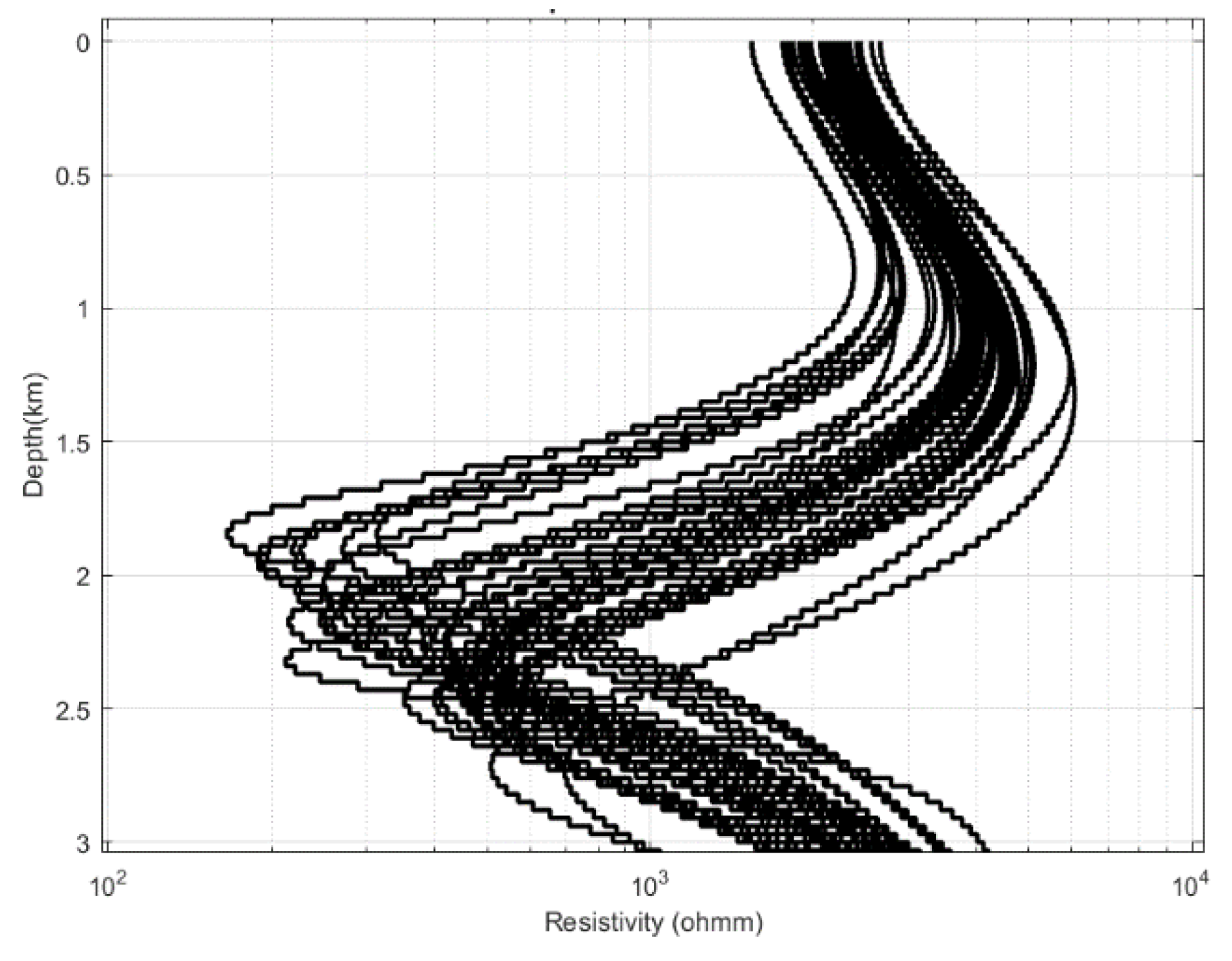
3.1. Conjugate Gradient Adaptive Unconstrained 1D Inversion

The nonlinear least-squares iterative 1D inversion algorithm is based on the conjugate gradient method with adaptive regularization [38]. The algorithm uses weighting of the inverted parameters, and in this way provides equal model discretization in shallow and deep parts of an inverting section. The data inversion software was developed by Golubev [39], specifically for MobileMT data in 2019, for rapid data analysis and predictive targeting at the initial stage of data interpretation.
The algorithm uses regularization to get stable and geologically meaningful solutions. We minimize parametric functional P which consists of data misfit, φ and stabilizer, S (L2 norm of difference between initial and fitted model) multiplied by a regularization parameter α.
P(m) = φ(m) + αS(m)
where,
φ (m) = ‖dobs − dmod2
is data misfit and,
S(m) = ‖m − mini2
is a stabilization term.
An example of the modelled resistivity curve (1D model) for measurement stations along a survey line is shown in Figure 4. The inverted data for each observation station are combined to create resistivity-depth cross-sections along a line (Figures 6a and 8).

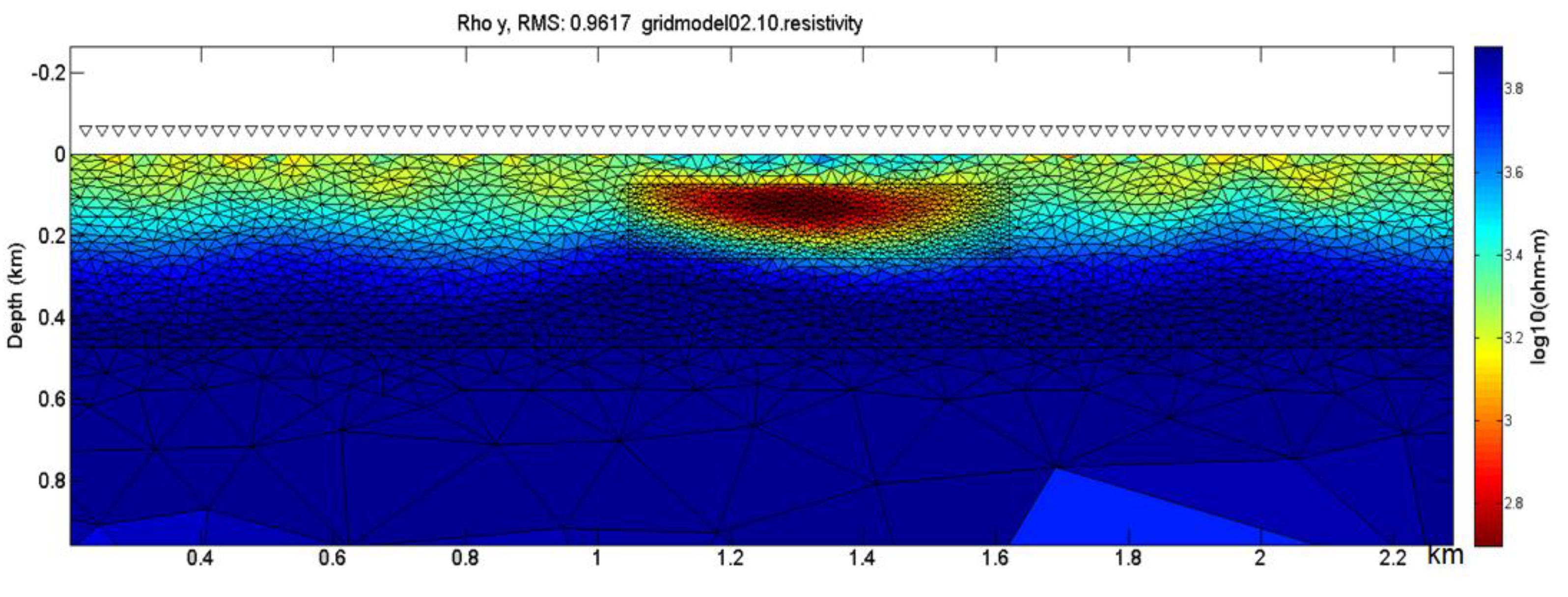
3.2. Detail and Goal-Oriented 2D Data Inversion

The 2D inversion of MobileMT EM data is performed for surveyed lines using the adaptive finite element and regularized non-linear MARE2DEM program code [40,41].
The main features of the MARE2DEM code include:
  • It is the first goal-oriented adaptive finite element code for MT;
  • Uses structured and unstructured model grids (mesh);
  • 2.5D EM problem statement (i.e., 3D EM source field in a 2D conductive environment);
  • Parallel calculations implementation.
The use of unstructured grids by MARE2DEM is very effective for representing complex structures and discrete targets (Figure 5).
Other examples of applying 2D inversion to MobileMT data are shown in Figures 7b and 10.

3.3. 3D Data Inversion

Several approaches and algorithms exist to implement 3D inversion of MobileMT data. One of them is realized by Geotexera Inc. and Dr. Colin Farquharson’s research group at Memorial University of Newfoundland using a 3D minimum-structure method with an iterative model space, Gauss–Newton algorithm based on an unstructured tetrahedral mesh [42]. An example of 3D inversion results is presented in Figure 9.

4. Natural AEM Field Examples: Capabilities and Advantages of MobileMT

The technical solutions realized in the airborne MobileMT technology provided exploration capabilities which overcome limitations of other AEM systems based on different principles including those making use of controlled primary field sources.
The specific technical advancements that enable exploration advantages include:
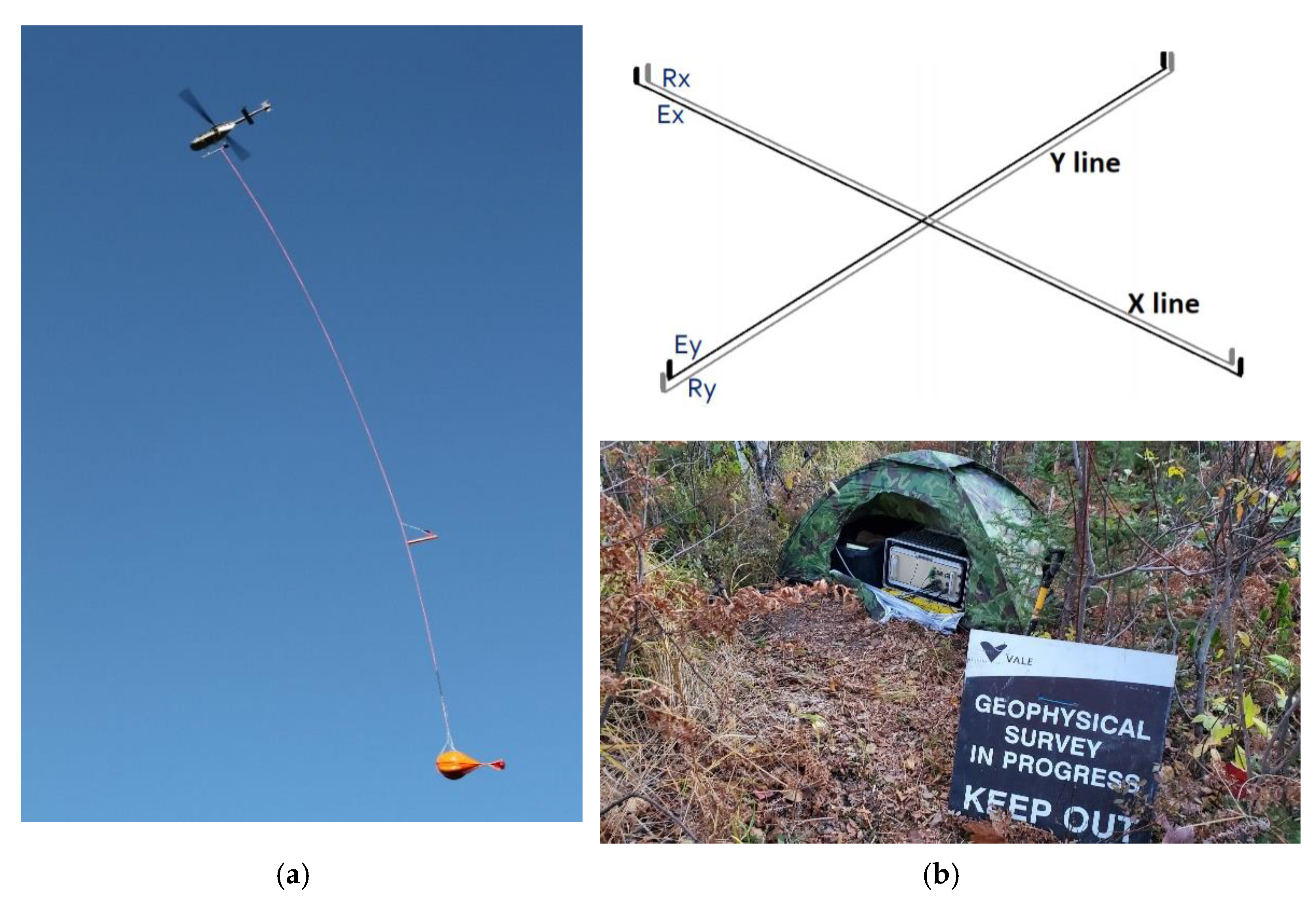
  • Measurement of magnetic field variations with three orthogonal coils (total field). This provides sensitivity to any direction of geoelectrical boundary, from horizontal to vertical;
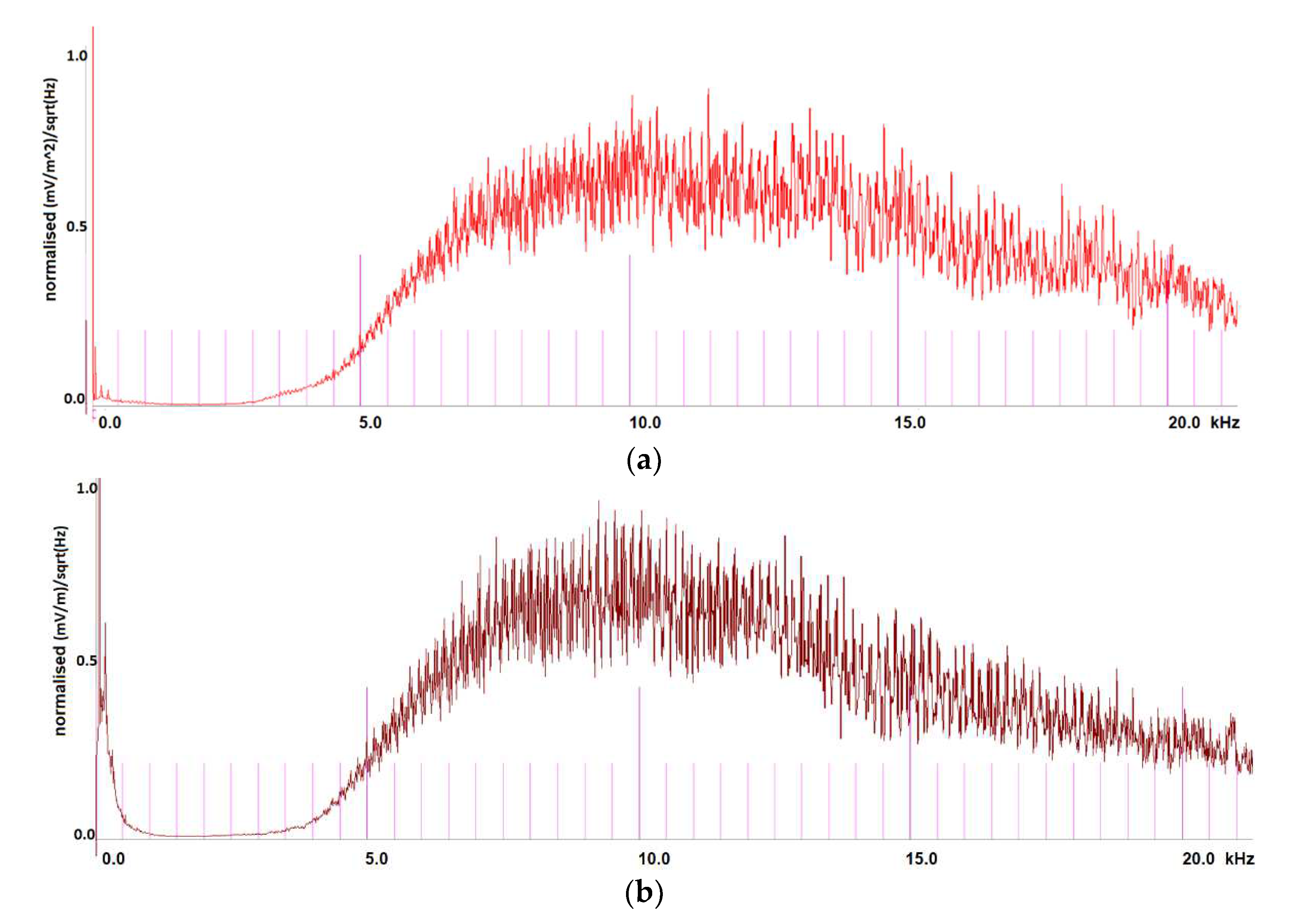
  • Measurements are obtained over 3 decades of frequency, from 19 Hz to 26 kHz. This allows imaging near surface structures as well as those at > 1 km depth, depending on the conductance of the geologic environment;
  • The frequency range is divided into 30 windows that provide high in-depth resolution and a good opportunity for data selection, depending on cultural noise sources, natural EM field signal, and exploration goals;
  • The high sampling rate of the airborne data as well as the base station data result in bias free and denoised data.
  • The main advantages of the natural field method, in general, include:
  • The depth of investigation always exceeds the capabilities of systems with controlled sources;
  • The method is sensitive not only to conductors, but to resistivity differences in the range of thousands and tens of thousands of ohm-m; which is specifically a challenge for existing time domain systems. At the other end, for time-domain systems, response from superconductors (hundreds and thousands of Siemens) is not visible in the off-time channels of the dB/dt stream. For the natural field EM principle, it is not a limitation;
  • There is no critical dependence on the terrain clearance of the system. This allows for less aggressive flying in rugged terrain conditions, improving the overall safety of data acquisition;
  • Inherent to impulse time-domain systems are IP and SPM parasitic effects that badly influence the inductive response. These effects are not formed, and do not distort the secondary electromagnetic field data for methods using natural fields.
The following field examples and case studies demonstrate the capabilities and advantages using real data.

4.1. Aylmer IOCG Mineralization Exploration

The Aylmer Property, which is prospective for IOCG (iron oxide copper gold)-style mineralization, is located in the Sudbury-Wanapitei Lake area (Northern Ontario, ON, Canada) where airborne time-domain systems are not effective since the environment is quite resistive, and the variations in resistivity that are of interest are in the range of thousands of ohm-ms. A historical airborne EM time-domain survey over the property did not detect noteworthy anomalies [43].
A helicopter borne MobileMT survey was conducted over the property to highlight evidence of a buried mineralization controlling system at depth. Deep, weakly conductive structures and structural resistivity contrasts were revealed along with magnetic features (Figure 6). The deep-seated and subvertical downward-conductive zones could be two components of the controlling mineralization system—the source and feeding zones for hydrothermal fluids.
The results of the MobileMT survey in Northern Ontario demonstrate the superior performance of this airborne natural field EM technology in its ability to detect comparatively weakly conductive features in resistive terrain. A direct comparison with airborne time-domain data along a line shows the resistivity detection limitations of time-domain methods compared to the capabilities of MobileMT [44]. In addition, the example demonstrates sensitivity of the system to complex geoelectric boundaries and contacts, from horizontal to vertical.

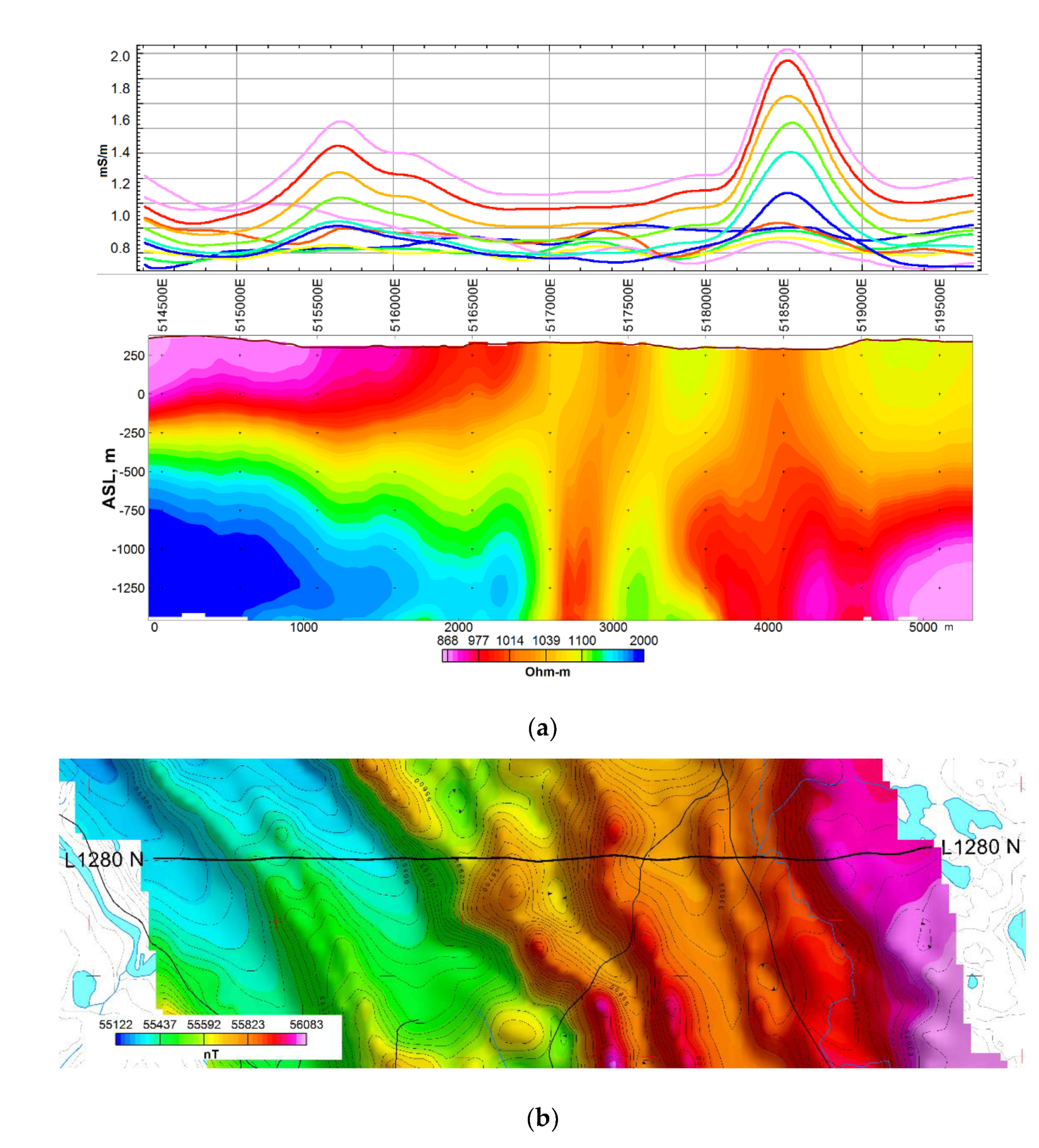
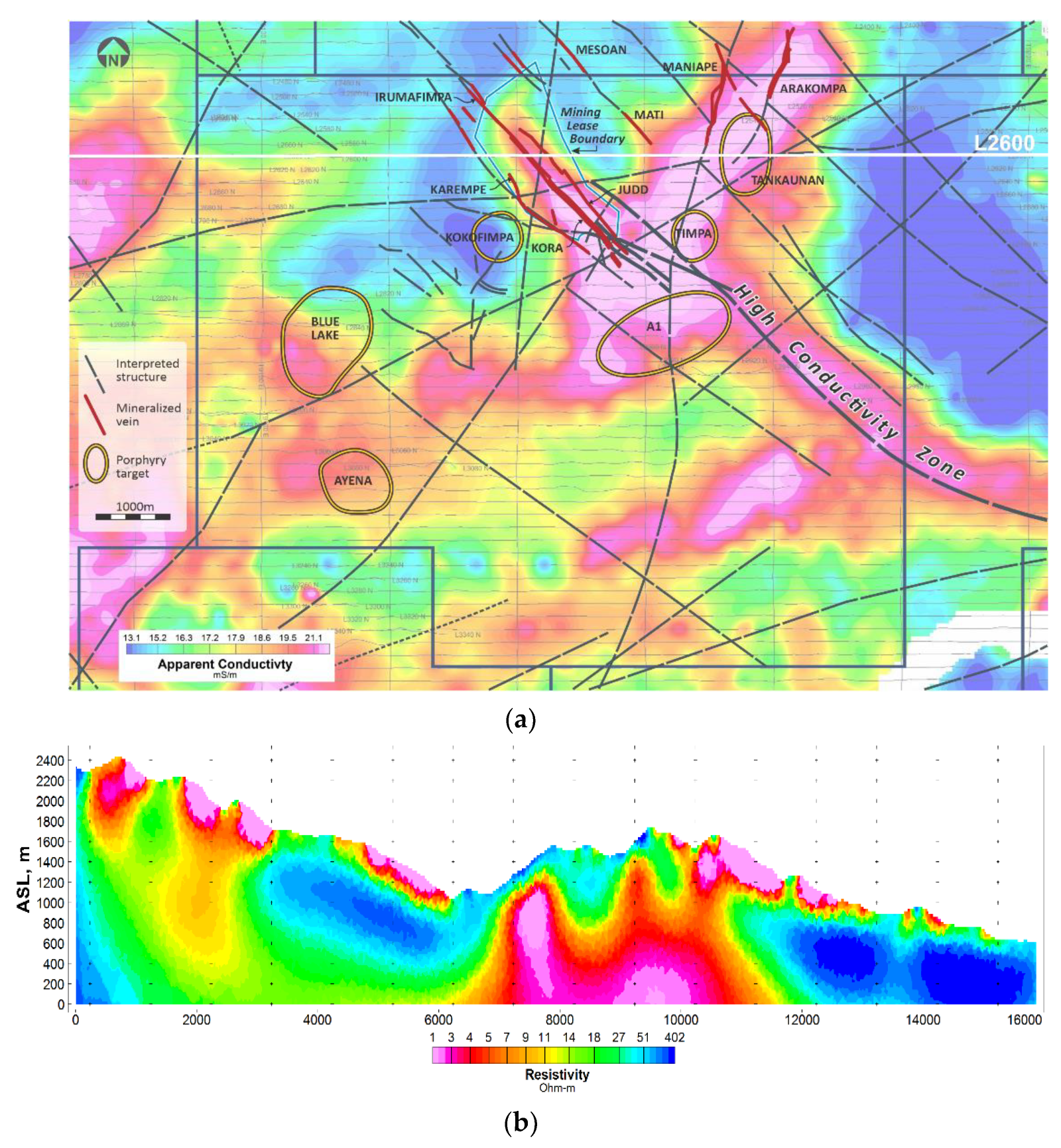
4.2. Kainantu Exploration

The Kainantu property is located within the New Guinea Thrust Belt, close to its northern contact with the Finisterre Terrane [45]. The contact is marked by the northwest trending Ramu-Markham Fault, a major suture zone that marks the northern margin of the Australian Craton. The belt is characterized by several north-northeast trending fault zones that commonly host major ore deposits. Mineralization on the property includes Au, Ag and Cu occurring in low sulphidation epithermal Au-telluride veins, Au-Cu-Ag sulphide veins of Intrusion Related Gold Copper (“IRGC”) affinity, less explored porphyry Cu-Au systems and alluvial gold. The property encompasses an epithermal vein field consisting of multiple known and highly prospective vein systems: Kora, Irumafimpa, Karempe, Judd, Kora South, Mati, Maniape, and Arakompa.
The survey area is typified by rugged mountainous terrain with conductive overburden, which makes it very challenging for AEM surveys with controlled primary field sources. The MobileMT survey results show excellent correlation between a known sulphidic Cu-Au vein field (Figure 7a) and conductive structures and identify deep dome similar structures, demonstrating potential for porphyry systems (Figure 7b).

4.3. Kimberlite Pipe

A MobileMT test survey was flown over known kimberlites, in the Lake Timiskaming Kimberlite field in north-eastern Ontario. The kimberlites in this field are hosted by Proterozoic sediments, including thinly bedded siltstone, which are highly resistive. The KL-22 kimberlite pipe was discovered in 2004 by Contact Diamond Corp. [46]. The kimberlite pipe is covered by 10 to 20 m of glacial sediments, and is almost unweathered at its subcropping surface [47]. However, there is evident alteration, and the rock is considered to be a vocalniclastic kimberlite breccia [48].
The results of the MobileMT survey over the KL-22 kimberlite are provided in Figure 8 and Figure 9. The location of the kimberlite is delinated through an increase in the apparent conductivity data for all frequencies, but particularly at higher frequencies, demonstrating the ability of the MobileMT technology to resolve near surface conductive features along with deep structures.

4.4. Olympic Dam Copper Province

The copper-cobalt-silver mineralization at Elizabeth Creek (South Australia, ~100 km south of the Olympic Dam deposit), are hosted by flat-lying undeformed shales of the Tapley Hill Formation of Late Proterozoic Age [49]. The mineral deposits are composed of sediment-hosted fine-grained sulphides. Copper is primarily hosted in chalcopyrite, with accessory chalcocite and bornite. The Emmie Bluff prospect in the north of the Elizabeth Creek project area is an underground target, with the top of mineralization sitting at approximately 400m [50].
Ground magnetotelluric data were acquired between 0.001 and 250 Hz with a site spacing of approximately 500 m. Twelve frequencies were involved in the MobileMT data inversion between 27 and 445 Hz. The depth range of the sections is limited by the MobileMT depth of investigation estimated for the survey area. The results of inverting the ground magnetotelluric data vs the MobileMT data are provided in Figure 10.
This field example demonstrates exploration capabilities of the airborne MobileMT technology in a highly conductive environment with decent depth of investigation. Direct comparison of the airborne EM with ground MT resistivity shows a good match between the two resistivity-depth images.

5. Discussion

Electromagnetic surveys are now routinely performed from airborne platforms. MobileMT airborne EM technology was developed to overcome limitations faced by currently available commercial active and passive source AEM systems. In comparison with active source methods, passive primary field source methods are less limited in depth of investigation in any geoelectrical conditions and less dependent on survey terrain clearance. In addition, while active-source time-domain AEM data are mainly sensitive to conductive structures, passive source methods are sensitive to conductive and resistive structures with good resolution in comparatively narrow resistivity ranges.
The 5-component natural field method, as employed by MobileMT, is a combination of two magnetotelluric approaches: namely audiomagnetotellurics and magnetovariational prospecting. By combining the two methods, which are sensitive to the behavior of sub-horizontal layers and sub-vertical layers, respectively, one can achieve omnidirectional sensitivity.
MobileMT can be used for diverse exploration models with wide and narrow ranges of resistivity differentiations. The field examples presented in this paper emphasize the strengths of MobileMT, first showing the ability of the technology to resolve weakly conductive targets in a relatively resistive environment for the Aylmer property.
AEM systems have faced challenges when conductive ore bodies are located in host rocks of very low resistivity, for example, in Australia. Additionally, in the presence of conductive overburden, the energy limitations of active source AEM systems coupled with the limiting impact of near-surface conductive material on the skin depth, significantly compromise the depth of investigation. The ability of MobileMT to resolve the subsurface geoelectric environment even in the presence of conductive overburden and in a conductive environment was demonstrated with excellent correlation between known structures and the acquired AEM data over the Kainantu property in PNG as well as in the Olympic Dam Copper province of the South Australia. In the Kainantu area case not only was the conductive geologic environment challenging, but the survey block had significant topographic relief. The system clearance varied considerably through the survey area (ranging from 10s of m’s to 400 m, with an average of approximately 80 m), but there is virtually no dependence of the output apparent conductivity data on the flying height.
Up until now, passive source methods have been stereotyped as only capable of resolving deep and large structures. However, the results from the test survey flown in the Lake Timiskaming Kimberlite field in north-eastern Ontario show that the MobileMT technology is capable of resolving discrete, near-surface targets, such as kimberlites, as well, making it an attractive tool for diamond exploration and other comparatively near-surface, discrete exploration targets.
As technological advancements continue, and improvements are made to both the hardware and software involved in the MobileMT technology, it is anticipated to become an increasingly reliable and versatile tool for the mining and resource industry. Advancements to the 1D modelling used to invert the apparent conductivity data and retrieve the resistivity depth distribution are on-going to improve the agreement between the theory and the real-world implementation. In addition, 2D inversion codes, such as MARE2DEM [41], and 3D inversions [42], are compatible with MobileMT data and can provide more accurate resistivity models in specific circumstances.

Author Contributions

Conceptualization, A.P. and A.B.; methodology, P.K.; data processing software, P.K.; data inversions: A.P. and A.S.; data processing, validation and curation, A.B. and A.P.; formal analysis, A.S.; investigation, A.P.; resources, A.P. and A.S.; writing—original draft preparation, A.P.; writing—review and editing, A.S., A.B. and P.K.; visualization, A.P.; supervision, A.P.; project administration, A.B. and A.P. All authors have read and agreed to the published version of the manuscript.

Funding

This research received no external funding.

Data Availability Statement

Applicable at the personal request addressed to Expert Geophysics Limited.

Acknowledgments

the authors wish to thank K92 Mining, CODA Minerals, Transition Metals Corp., VALE Canada Limited (Exploration) for permissions to use related pictures and data in the paper.

Conflicts of Interest

The authors declare no conflict of interest.

References

  1. Nabighian, M.N. Application, Parts A and B. In Electromagnetic Methods in Applied Geophysics; Investigations in Geophysics; Society of Exploration Geophysicists: Tulsa, OK, USA, 1991; Volume 2, ISBN 978-1-56080-022-4. [Google Scholar]
  2. Eaton, P.A.; Anderson, R.G.; Queen, S.V.; Nilsson, B.Y.; Lauritsen, E.; Barnett, C.T.; Olm, M.; Mitchell, S. Helicopter Time-Domain Electromagnetics—Newmont and the NEWTEM Experience. Geophysics 2013, 78, W45–W56. [Google Scholar] [CrossRef]
  3. Fountain, D. 60 Years of Airborne EM—Focus on the Last Decade. In Proceedings of the AEM2008—International Conference on Airborne Electromagnetics, Haikko Manor, Finland, 28–30 May 2008; pp. 1–5. [Google Scholar]
  4. Allard, M.; Milkereit, B. On the Origin of the HTEM Species. In Proceedings of the Exploration 07: Fifth Decennial International Conference on Mineral Exploration, Toronto, ON, Canada, 9–12 September 2007; pp. 355–374. [Google Scholar]
  5. Macnae, J. Advances in Electromagnetic Data Processing: Noise, Signal, SPM and AIP. In Proceedings of the Exploration 17: Sixth Decennial International Conference on Mineral Exploration, Toronto, ON, Canada, 21–25 October 2017; pp. 191–208. [Google Scholar]
  6. Tikhonov, A.N. On Determining Electrical Characteristics of the Deep Layers of the Earth’s Crust. Dokl. Akad. Nauk. SSSR 1950, 73, 295–297. [Google Scholar]
  7. Cagniard, L. Basic Theory of the Magneto-Telluric Method of Geophysical Prospecting. Geophysics 1953, 18, 605–635. [Google Scholar] [CrossRef]
  8. Dmitriev, V.I.; Berdichevsky, M.N. The Fundamental Model of Magnetotelluric Sounding. Proc. IEEE 1979, 67, 1034–1044. [Google Scholar] [CrossRef]
  9. Berdichevsky, M.N.; Dmitriev, V.I.; Golubtsova, N.S.; Mershchikova, N.A.; Pushkarev, P.Y. Magnetovariational Sounding: New Possibilities. Izv. Phys. Solid Earth 2003, 39, 701–727. [Google Scholar]
  10. Berdichevsky, M.N.; Zhdanov, M.S.; Pyankova, T. Advanced Theory of Deep Geomagnetic Sounding. Methods Geochem. Geophys. 1984, 19, 480. [Google Scholar]
  11. Varentsov, I.M.; Kulikov, V.A.; Yakovlev, A.G.; Yakovlev, D.V. Possibilities of Magnetotelluric Methods in Geophysical Exploration for Ore Minerals. Izv. Phys. Solid Earth 2013, 49, 309–328. [Google Scholar] [CrossRef]
  12. Ward, S.H.; Cartier, W.O.; Harvey, M.A.; McLaughlin, G.H.; Robinson, W.A. Prospecting by Use of Natural Alternating Magnetic Fields of Audio and Sub-Audio Frequencies. Trans. Can. Inst. Min. Met. 1958, 61, 261. [Google Scholar]
  13. Ward, S.H. AFMAG—Airborne and Ground. Geophysics 1959, 24, 761–787. [Google Scholar] [CrossRef]
  14. Ward, S.H.; O’Donnell, J.; Rivera, R.; Ware, G.H.; Fraser, D.C. AFMAG—Applications and Limitations. Geophysics 1966, 31, 576–605. [Google Scholar] [CrossRef]
  15. Ward, S.H.; O’Brien, D.P.; Parry, J.R.; McKnight, B.K. AFMAG—Interpretation. Geophysics 1968, 33, 621–644. [Google Scholar] [CrossRef]
  16. Thomson, S.; Fountain, D.; Watts, T. Airborne Geophysics–Evolution and Revolution. In Proceedings of the Exploration 07: Fifth Decennial International Conference on Mineral Exploration, Toronto, ON, Canada, 9–12 September 2007; Volume 7, pp. 19–37. [Google Scholar]
  17. Morrison, E.; (Geotech Ltd., Toronto, ON, Canada). Personal Communcation, 2005.
  18. Ward, S.H. Part C: The Electromagnetic Method. In Mining Geophysics Volume II, Theory; Society of Exploration Geophysics: Tulsa, OK, USA, 1967; pp. 224–372. [Google Scholar]
  19. Dentith, M.; Mudge, S.T. Geophysics for the Mineral Exploration Geoscientist; Cambridge University Press: Cambridge, UK, 2014. [Google Scholar] [CrossRef] [Green Version]
  20. Nabighian, M.N.; Asten, M.W. Metalliferous Mining Geophysics—State of the Art in the Last Decade of the 20th Century and the Beginning of the New Millennium. Geophysics 2002, 67, 964–978. [Google Scholar] [CrossRef]
  21. Christopherson, K.R. EM in the 21st Century–Looking for Oil, Gas and Water. In Proceedings of the 16th Workshop on Electromagnetic Induction in the Earth, Santa Fe, NM, USA, 16–22 June 2002; pp. 16–22. [Google Scholar]
  22. Lo, B.; Kuzmin, P.; Morrison, E. Field Tests of Geotech’s Airborne AFMAG EM System. In Proceedings of the Australian Earth Sciences Convention 2006—18th ASEG Conference, Melbourne, Australia, 2–7 July 2006; pp. 1–5. [Google Scholar]
  23. Kaminski, V.F.; Kuzmin, P.; Legault, J.M. AirMt–Passive Airborne EM System. In Proceedings of the 3rd CMOS-CGU Congress, Ottawa, ON, Canada, 31 May–4 June 2010. [Google Scholar]
  24. Legault, J.M. Ten Years of Passive Airborne AFMAG EM Development for Mineral Exploration. In Proceedings of the 82nd Society of Exploration Geophysicists International Exposition and Annual Meeting, Las Vegas, NV, USA, 4–9 November 2012. [Google Scholar]
  25. Labson, V.F.; Becker, A.; Morrison, H.F.; Conti, U. Geophysical Exploration with Audiofrequency Natural Magnetic Fields. Geophysics 1985, 50, 656–664. [Google Scholar] [CrossRef]
  26. Gribenko, A.V.; Zhdanov, M.S.; Cox, L.H.; Wilson, G.A.; Legault, J.; Zhao, S.; Fisk, K. 3D Inversion of AirMt AFMAG Data. In Proceedings of the 82nd Society of Exploration Geophysicists International Exposition and Annual Meeting, Las Vegas, NV, USA, 4–9 November 2012. [Google Scholar]
  27. Vozoff, K. The Magnetotelluric Method in the Exploration of Sedimentary Basins. Geophysics 1972, 37, 98–141. [Google Scholar] [CrossRef]
  28. Morrison, E.B.; Kuzmin, P.V. System, Method and Computer Product Geological Surveying Utilizing Natural Electromagnetic Fields. U.S. Patent No. 6,876,202, 5 April 2005. [Google Scholar]
  29. Legault, J.M.; Prikhodko, A.; Tishin, P.; Dodds, J. New Airborne EM Systems Development for 2013. In Proceedings of the CAMESE Innovations Forum, Toronto, ON, Canada, 3 March 2013. [Google Scholar]
  30. Lo, B.; Zang, M. Numerical Modeling of Z-TEM (Airborne AFMAG) Responses to Guide Exploration Strategies. In Proceedings of the 78th Society of Exploration Geophysicists International Exposition and Annual Meeting, Las Vegas, NV, USA, 9–14 November 2008; pp. 1098–1102. [Google Scholar]
  31. Jansen, J.C.; Cristall, J.A. Mineral Exploration Using Natural EM Fields. In Proceedings of the Exploration 17: Sixth Decennial International Conference on Mineral Exploration, Toronto, ON, Canada, 21–25 October 2017. [Google Scholar]
  32. Kuzmin, P.V.; Borel, G.; Morrison, E.; Dodds, J. Geophysical Prospecting Using Rotationally Invariant Parameters of Natural Electromagnetic Fields. U.S. Patent No. 8,289,023, 16 October 2012. [Google Scholar]
  33. Legault, J.M.; Kumar, H.; Milicevic, B.; Hulbert, L. ZTEM Airborne Tipper AFMAG Test Survey over a Magmatic Copper-Nickel Target at Axis Lake in Northern Saskatchewan. In Proceedings of the 79th Society of Exploration Geophysicists International Exposition and Annual Meeting, Houston, TX, USA, 25–30 October 2009; pp. 1272–1276. [Google Scholar]
  34. Lo, B.; Legault, J.; Kuzmin, P.; Combrinck, M. Z-TEM (Airborne AFMAG) Tests over Unconformity Uranium Deposits. In Proceedings of the Australian Earth Sciences Convention 2009—20th ASEG Conference, Adelaide, Australia, 22–26 February 2009; pp. 1–6. [Google Scholar]
  35. Sattel, D.; Witherly, K.; Kaminski, V. A Brief Analysis of MobileMT Data. In Proceedings of the 82nd Society of Exploration Geophysicists International Exposition and Annual Meeting, San Antonio, TX, USA, 15–20 September 2019; pp. 2138–2142. [Google Scholar]
  36. Bagrianski, A.; Kuzmin, P.; Prikhodko, A. AFMAG Evolution–Expanding Limits. In Proceedings of the SAGA 2019—16th Bienniel Conference and Exhibition, Durban, South Africa, 6–9 October 2019; pp. 1–4. [Google Scholar]
  37. Zhdanov, M.S. Geophysical Electromagnetic Theory and Methods; Elsevier: Amsterdam, The Netherlands, 2009. [Google Scholar]
  38. Zhdanov, M.S. Geophysical Inverse Theory and Regularization Problems; Elsevier: Amsterdam, The Netherlands, 2002; Volume 36. [Google Scholar]
  39. Golubev, N.G.; Varentsov, I.M. MT-Data Inversion: Stable Optimization Methods and Interactive Graphics. In Proceedings of the XII Workshop on EM-Induction in the Earth, Brest, France, 8–13 August 1994. [Google Scholar]
  40. Key, K.; Ovall, J. A Parallel Goal-Oriented Adaptive Finite Element Method for 2.5-D Electromagnetic Modelling. Geophys. J. Int. 2011, 186, 137–154. [Google Scholar] [CrossRef]
  41. Key, K. MARE2DEM: A 2-D Inversion Code for Controlled-Source Electromagnetic and Magnetotelluric Data. Geophys. J. Int. 2016, 207, 571–588. [Google Scholar] [CrossRef]
  42. Jahandari, H.; Farquharson, C.G. 3-D Minimum-Structure Inversion of Magnetotelluric Data Using the Finite-Element Method and Tetrahedral Grids. Geophys. J. Int. 2017, 211, 1189–1205. [Google Scholar] [CrossRef]
  43. Fiset, N. Report on a Helicopter-Borne Versatile Time Domain Electromagnetic (VTEM Plus) and Horizontal Magnetic Gradiometer Geophysical Survey; Geotech Ltd.: Aurora, ON, Canada, 2011. [Google Scholar]
  44. MobileMT Survey over the IOCG-AYLMER Property (a Greenfield Case Study)—Expert Geophysics Limited. Available online: https://www.expertgeophysics.com/wp-content/uploads/2020/12/MobileMT-survey-over-the-Aylmer-IOCG.pdf (accessed on 4 April 2022).
  45. Kainantu Mine. Available online: https://k92mining.com/kainantu-mine/ (accessed on 4 April 2022).
  46. Sobie, P. Report on 2003–2004 Exploration on the Klock Property Larder Lake Mining Division; Northeastern Ontario of Sudbury Contact Mines Limited: Toronto, ON, Canada, 2007. [Google Scholar]
  47. Sobie, P.; Lang, G. Technical Report on the Timiskaming Diamond Project; NE Ontario and NW Quebec of Contact Diamond Corp: Toronto, ON, Canada, 2006. [Google Scholar]
  48. McClenaghan, M.B.; Kjarsgaard, I.M.; Kjarsgaard, B.A. Indicator Mineralogy of the KL-01 and KL-22 Kimberlites, Lake Timiskaming Kimberlite Field, Ontario; Geological Survey of Canada Open File 5800; Natural Resources Canada: Ottawa, QC, Canada, 2008. [Google Scholar]
  49. Cowan, D.; Dentith, M. Unconformity-Related Copper Mineralisation on the Stuart Shelf, South Australia: Geophysical Responses of Mineralisation and the Mineralised Environment. In Proceedings of the Australian Earth Sciences Convention 2003—16th ASEG Conference, Adelaide, Australia, 16–19 February 2003; pp. 197–212. [Google Scholar]
  50. Elizabeth Creek—CODA Minerals. Available online: https://www.codaminerals.com/projects/ (accessed on 4 April 2022).
Figure 1. Approximate depth of investigation estimation of different airborne electromagnetic principles.
Minerals 12 00583 g001
Figure 2. MobileMT system: (a) H-field airborne bird with three orthogonal induction coils located inside a fiberglass shell, towed by a helicopter; (b) E-field base station consists of four independent grounded electrical lines measuring the horizontal components of the electrical field and the data acquisition system.
Minerals 12 00583 g002
Figure 3. Airborne magnetic X-coil spectrum up to 20,000 Hz range (a) with the corresponded electric X-line spectrum recorded on the ground (b).
Minerals 12 00583 g003
Figure 4. Combined resistivity modelled curves along a survey line.
Minerals 12 00583 g004
Figure 5. Resistivity-depth sections with the unstructured grid model.
Minerals 12 00583 g005
Figure 6. MobileMT apparent conductivity profiles ranging from 42 Hz to 13,619 Hz (a) top; resistivity-depth section (a) bottom; magnetic field map with the survey line position (b).
Minerals 12 00583 g006
Figure 7. (a) MobileMT apparent conductivity color grid (86 Hz) with overlapped mineralized veins, structures, and porphyry targets; (b) Resistivity-depth section along 2600 survey line (2D inversion).
Minerals 12 00583 g007
Figure 8. MobileMT apparent conductivity profiles (top) along the line that transects KL−22 kimberlite pipe. The frequency range from 80 Hz (blue) to 13,571 Hz (pink); resistivity-depth inverted section (bottom).
Minerals 12 00583 g008
Figure 9. Conductive volumes of resistivity-depth model derived from 3D inversion (Geotexera Inc.). KL−22 kimberlite pipe.
Minerals 12 00583 g009
Figure 10. Resistivity sections over the same line derived and inverted from MobileMT and from ground MT data provided by CODA Minerals. Emmie Bluff block.
Minerals 12 00583 g010
Table 1. Technical specifications of AFMAG system [14].
Detector typeTwo inductive coils in the air at 450 to the horizontal and to each other in the direction of flight. The components are compared electronically (H-field).
Output dataTilt component of the magnetic field along the line direction. Deflections are proportional to the tilt of the plane of polarization.
Frequency bands (Hz) Typical 150; 510.
Data Sampling RateNo digital recording.
Bird tilting motion compensationYes.
Signal biasYes.
Sensitivity to subsurface
geoelectrical differentiations
It is difficult or impossible to recover conductors with parallel axes to the direction of the inducing field.
Table 2. Technical specifications of the ZTEM system.
Detector typeOne vertical field inductive coil in the air (H-field);
Two horizontal field inductive coils on the ground (H-field).
Output dataX and Y in-phase and quadrature tipper data.
Frequency bandsTypical 32, 45, 90, 180, 360, 720 Hz [33,34].
Data Sampling Rate2000 Hz [30].
Bird tilting motion compensationYes.
Signal biasYes.
Sensitivity to subsurface
geoelectrical differentiations
Lack of ability to image layered geology; Sensitivity “to current density variations caused by conductivity contrasts, but not to the absolute conductivities themselves” [31].
Table 3. Technical specifications of the MobileMT system.
Detector typeThree orthogonal inductive coils in the air (H-field); two pairs perpendicular grounded electric lines (E-field).
Output dataAdmittance data (apparent conductivity).
Frequency bandsUp to 30 frequency windows in the 19-26,000 Hz range.
Data Sampling Rate73,728 Hz.
Bird tilting motion compensationNot required.
Signal biasNo.
Sensitivity to subsurface
geoelectrical differentiations
Sensitive to the absolute conductivities and to geoelectrical boundaries of any direction.
Publisher’s Note: MDPI stays neutral with regard to jurisdictional claims in published maps and institutional affiliations.

