Abstract
The tailing paste thickening technology was investigated to achieve goaf reduction treatment and tailing resource utilization of metal mines and reach the effect of controlling two hazards with one waste. However, superfine tailing particles could easily form suspended water-locking flocs in the thickening process, which seriously affected the increase in the underflow concentration in the thickener. Undisturbed compression-stage bed samples were extracted using an in situ sampling method through a continuous dynamic thickening experiment. Then, the morphologies and geometrical structures of micropores were analyzed through high-precision computed tomography scanning. Subsequently, the influences of the shear evolution of pore structure and seepage channel on the dewaterability of underflow slurry were explored by combining Avizo software and 3D reconstruction technology. The thickening and dewatering mechanism of underflow slurry was also revealed. Results showed that under the shear action, the flocs were deformed and compacted, forming a high-concentration underflow. On this basis, the original micropores were extruded, deformed and segmented. Moreover, many loose micropores were formed, the connectivity became poor and the total porosity declined. The diameter of the water-conducting channel in the sample was enlarged because of the shear force and the seepage effect improved. The maximum flow velocity inside the pores was 1.537 μm/s, which was 5.49% higher than that under the non-shear state.
1. Introduction
The mining industry is vital for national security and economic development [1,2,3,4]. In the global economy, more than 90%, 80% and 75% of energy resources, industrial raw materials and agricultural production materials, respectively, are derived from mineral resources. The continuous development and utilization of metal mineral resources have made the massive goaf and tailing reservoir formations two major dangerous sources, which seriously threaten the ecological environment and human security [5,6,7].
Unclassified tailing paste pumping filling is a green disposal technology. In particular, the preparation of unclassified surface tailings into paste materials is not prone to dewatering, segregation and precipitation caused by underground paste filling and surface paste stockpiling. This technology utilizes surface wastes to eliminate tailing reservoirs gradually; it can also govern underground goaves and control the collapse of mines, reach goaf reduction and tailing resource utilization of metal mines and contribute to the sufficient recycling of water resources. This technology has the advantages of safety, environmental friendliness, low cost and high efficiency [8,9]. However, the ultrafine tailing particles with water can easily form a flocculent net-like solid–liquid colloidal sol. Consequently, a large quantity of moisture cannot be drained, leading to the low concentration of underflow slurry; this scenario has become a bottleneck in the development of the paste filling method [10,11,12,13].
Some scholars have systematically investigated the flocculation, sedimentation and solidification characteristics of flocculants for tailing slurry to mitigate the dewatering of tailing slurry and thickened beds [14,15,16,17,18,19]. Although the new types of flocculants can form a compact floc structure and possess high strength by changing the bridging and flocculating environment between particles to improve the solidification efficiency of tailing beds, the tailing flocs exhibit strong porosity and contain a large quantity of water after flocculation; thus, the retained moisture can be released only through further compaction [20,21,22]. Xu et al. [23] studied the influences of solid content, adhesive proportion and cement reagent type of tailings on microstructural evolution. Deng et al. [24,25] analyzed the relationships of compressive strength with the proportion of pores with different radiuses and fractal dimensions according to the nuclear magnetic resonance porosity tests and the fractal characteristics of pore structure. They also explored the microporous characteristics of cement tailing backfilling and determined that the floc net structure is an underlying cause that influences the dewatering effect and rheological parameters. The evolution of pore structure in the shear process has been rarely studied. Moreover, shear action is a key factor influencing the concentration of underflow slurry.
Researchers studying flocculation evolution found that appropriate shearing can improve collision efficiency, facilitate hydrophobic flocculation, reshape tailing floc arrangement and improve the dewatering process [26,27]. Therefore, shear solidification characteristics have gradually gained attention; the research contents involve turbulent shear, stirring shear, high-speed pump blade shear and torque of rake rack [28,29,30]. Moreover, the flocs are almost spherical because the shear rate is elevated and their size and structure change after the shear [31]. Many small flocs are formed in the net structure of tailing beds because of the shear action [32]. Researchers combined computed tomography (CT) scanning and simulation to explore the micropore structural changes of tailings before and after the shear through thickening experiments and revealed the shear strengthening mechanism in the bed thickening process [33]. The research findings indicated that the net structure of flocs can be destructed by the shear action and natural fine particles can fill micropores under gravitational force and shear conditions [34]. On the basis of a continuous thickening experiment, Chen et al. [35] studied the dewaterability of tailings under shear action, explored the pore distribution in the thickening process via CT scanning and discovered that the pore structures become complex with the bed height. The connectivity between pores was also enhanced and water-conducting channels were formed, facilitating the drainage of sealing water inside flocs. Jiao et al. [36] identified the evolution of pore structure and pore throat before and after the shear using the pore network model (PNM) method. They also introduced pore evolution into thickening theory by considering the influence of shear action on the thickening process.
Under the shear action, floc particles are rearranged, water-conducting channels are formed through the connectivity between pores and the slurry is mainly dewatered in such water-conducting channels. However, the moisture release and seepage processes and mechanisms under the sealed state of flocs have been rarely studied thus far. Moreover, no further explanation has been given to the spatial-temporal characteristics of the distribution, formation, disappearance and connection of water seepage channels. In the present study, in situ sampling was performed in the tailing compaction zone of the ore bed, followed by an industrial CT scanning experiment and image processing, to observe the paste dewatering and concentration mechanisms from a mesoscopic angle. The processed images were placed under 3D reconstruction. Subsequently, a 3D Representative Elementary Volume model was constructed to reflect the morphological and geometrical structures of the micropores in the slurry, probe the influence of the shear evolution of pore structure and seepage channel on the dewaterability of underflow slurry and reveal its thickening and dewatering mechanisms.
2. Materials and Methods
2.1. Materials
The tailing particle gradation was detected using an LT-1064 laser particle analyzer, as shown in Figure 1. The unclassified tailing particle size distribution is displayed in Figure 2.
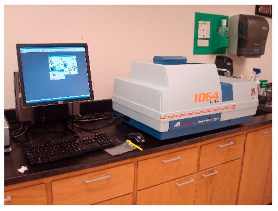
Figure 1.
Particle size analyzer.
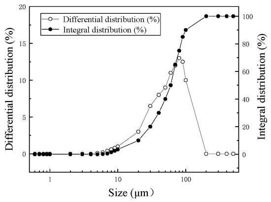
Figure 2.
Grain size distribution curve of the whole tailing sand.
The physical properties of the tailings are listed in Table 1. The average particle size was smaller than 0.03 mm. The particles smaller than 0.019, larger than 0.074 and larger than 0.037 mm accounted for more than 50%, less than 10% and less than 30%, respectively.

Table 1.
Basic physical parameters of tailings.
2.2. Methods
An intelligent small-scale continuous thickening experimental apparatus with a continuous feeding function was designed based on the industrial thickener in practice. The apparatus in this study could simulate the practical operation of a thickener to make the study results reasonable. Its structure and material object are as shown in Figure 3. The continuous thickening experimental platform is mainly composed of settling column, peristaltic pump, mixing pipe, rake frame and motor. Under the action of the peristaltic pump, the slurry and flocculant are mixed in the three-way pipe and transported to the settlement column through the feeding well. The rake frame starts to rotate under the action of the motor to provide shear force for the experiment and exert shear effect on the slurry in the settlement column. When the water at the upper part of the settlement column reaches the overflow hole, it will enter the overflow bucket through the overflow hole. The layout of the experimental equipment is shown in the figure below.
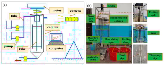
Figure 3.
Thickener experiment platform (a) effect drawing of experimental device (b) layout of laboratory equipment.
The basic parameters (e.g., feeding concentration, flocculent type and unit consumption) of the thickening experiment could be determined according to the intermittent experimental results. However, some parameters, such as solid flux, still needed further calculation. The solid flux of gravitational thickeners is generally 0.1–0.3 th−1 m−2.
Four factors were chosen in this experiment: solid flux, stirring rate of rake rack, feeding concentration and bed height. Three levels were set for each factor. The orthogonal experimental layout is seen in Table 2.
Table 2.
Experimental factors and level selection.
According to the continuous orthogonal experimental results, the feeding concentration was finally determined as 15%. The materials were diluted to 5% before they were mixed with the flocculant and the unit consumption of flocculant was 20 g/t. The feeding solid flux, bed height, residence time and rake rotation rate were 0.2 th−1 m−2, 20 cm, 3 h and 0.2 rpm, respectively.
The sample preparation of the solid–liquid mixture was the key to the CT scanning experiment [37,38,39,40]. The undisturbed compression-stage bed samples were extracted using the in situ sampling method. No shear force was exerted initially. After the target slurry was mixed with the flocculant, flocculating settling was performed through the gravity inside the settling column. When the bed height reached 20 cm, the mixture was kept for 0.5 h. Then, a sample was taken and marked as S1. The above process was repeated. Under the action of adding shear, when the bed height reaches 20 cm, the stirring time is 10 min, 30 min and 60 min, respectively, and the samples are marked as S2, S3 and S4, respectively. CT scan the four samples and the samples S1, S2, S3 and S4 represent stage 1 to stage 4 of the experimental process, respectively. The sampling process is depicted in Figure 4.
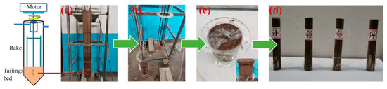
Figure 4.
Sampling process: (a) Flocculation and sedimentation process; (b) Disassembly of settlement column; (c) Select target bed; (d) Conduct sampling.
The scanning device used in the experiment was Phoenix v|tome|xs high-precision industrial microscopic CT scanning system shown in Figure 5. It is mainly composed of X-ray and gamma ray, detector system, data acquisition and transmission system and mechanical scanning, with design features of low maintenance rate and production orientation [41,42]. This system has become a high-speed and effective tool for quality detection through a simple and convenient loading tool, barcode scanning and a new one-button automatic CT function. The voltage and current of ray tube as 180 kV and 30 μA, respectively, which enables the ray to penetrate the sample and adjusts the CT imaging quality control parameters on this basis. After debugging, it is determined that the magnification is 1000 times, the scanning time of each slice is 2 s, the scanning rate of each projection (rotation angle of sample table) is 0.9° and the resolution of the scanning unit is 5 μm. The layer spacing is 5 μm (a pixel) and the scanning length is about 100 mm.
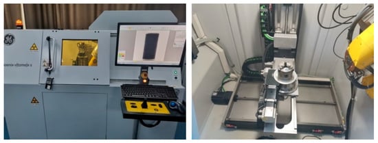
Figure 5.
Phoenix v|tome|xs high-precision industrial CT: (left) Scanning equipment; (right) Sample Placement.
3. Results and Discussion
3.1. Spatial Topological Structure of Pores in the Thickening Process
The pore structure inside the tailing slurry evolves under the shear action and the slurry thickening effect is affected by the pore size and spatial distribution [43]. Hence, the thickening effect of bed slurry can be evaluated by exploring the spatial topological properties of pores.
3.1.1. Porosity
Porosity is the ratio of the pore voxel value to the total value in a 3D reconstruction model. The pore structure and porosity of the four tailing samples are shown in Figure 6. The pore structure chart shows that the pores became loose and were broken because of the shear action.
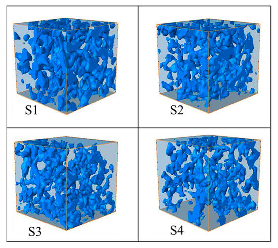
Figure 6.
Evolution of pore structure in bed slurry: The pore structures of samples S1, S2, S3 and S4 are shown in Figure.
Figure 7 indicates that the porosity of S1 was the maximum (46.48%) in the event of no shear action. The porosity presented a declining linear trend as the shear time passed. After the shear action was completed, the porosity was 37.46%, indicating a decline of 19.21%. This finding indicated that the unclassified tailing bed thickening effect could be enhanced by the shear action. The porosity of S1 to S2 showed minor changes. As a result of the stirring of the rake rack, the floc structure experienced recombination-fracture-recombination, the sealed holes inside the flocs were opened and the unconnected pores were rearranged before the sealing water was drained, thereby creating conditions for the subsequent drainage.
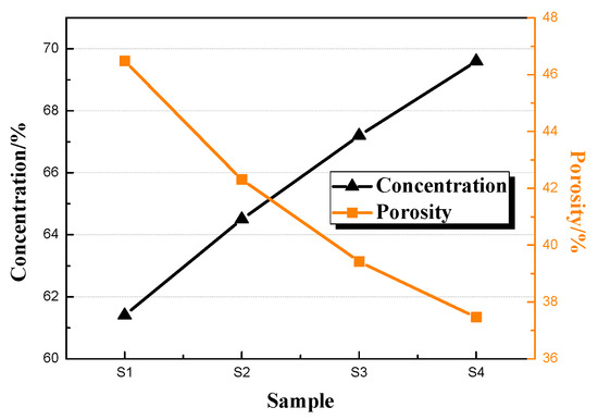
Figure 7.
Porosity concentration distribution curve.
The porosity of S2 and S3 dropped substantially from Stage II to Stage III. Moreover, the moisture was drained upward along the channels formed in Stage II and the tailing particles filled the pores downward. Thus, the underflow concentration was increased. In Stage IV, the new floccule structures were compact. Compared with the porosity of S3, the porosity of the new floccule structures slightly declined. Moreover, the pore structures were uniformly distributed. Hence, little water was sealed and the underflow slurry tended to be in a stable thickening state.
3.1.2. Pore distribution
The pore separation models of the four groups of samples are displayed in Figure 8. Different pores were distinguished using different colors. The 3D structure characteristics were extracted from the separated pore models and the number of pores were gradually reduced after the separation.
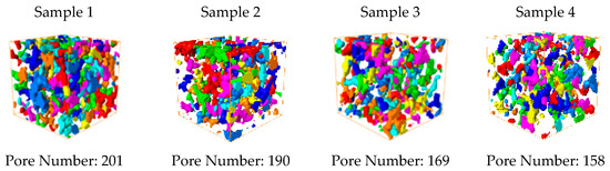
Figure 8.
Calibration chart of pore separation.
3.2. Property Analysis of PNMs
A PNM can also be called a “ball-and-stick model”, which consists of a ball body and a stick body. The former represents a large pore space, whereas the latter denotes the thin and long throat connecting pores. An equivalent PNM reflects the real distribution state of connected pore structures inside the slurry and the ball body and stick body become moisture hiding spaces. The water-conducting mechanism can be expounded by studying the PNM changes in the unclassified tailing thickening process and analyzing the topological characteristic parameters of the ball body and stick body.
As shown in Figure 9, the PNMs were correspondingly established for the four samples. The 3D reconstruction bodies indicated that many pores existed on the surface of S1. Under the shear action, a few dispersed balls existed on the surface of S4. The PNMs indicated that the internal pore structures continuously evolved. The key parameters, such as ball radius, stick radius and length and coordination number, were calculated through a series of data processing flows, as seen in Table 3.
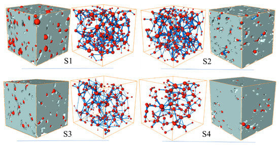
Figure 9.
Characterization of PNM evolution in shear process: The PNMs corresponding to samples S1, S2, S3 and S4 respectively in the figure.
Table 3.
Statistical table of hole throat size data.
Figure 9 and Table 3 show that in Stage I, the balls were large, whereas the sticks were small. Moreover, the moisture was mainly stored in balls, water-conducting channels were formed under the shear action, the average coordination number of S2 was the maximum with the best connectivity and the average radius of sticks was the maximum (31.38 μm), manifesting that many water-conducting channels were formed in Stage II. The shear force changed the network structure of flocs. Large balls could easily evolve into several small balls and form isolated pores because of the external shear force. The balls mainly exerted the effect of storing water, whereas the sticks played the water-conducting role, indicating that the pores became loose with poor connectivity and low porosity under the shear action.
3.3. Formation and Distribution of Water-Conducting Channels in the Thickening Process
Water-conducting channels are the upward movement channels for liquid. They are generated after the deformation and combination of flocs due to liquid enrichment during the upward drainage process of sealed water between stockpiled flocs. Static water-conducting channels, which are generated only through gravity and Brownian movement, can be easily sealed, leading to incomplete drainage. Dynamic channels, which are generated by compressing the floc structures and changing their spatial positions after the addition of shear action based on static channels, can hardly be sealed with a thorough drainage process.
The pore structures at the corresponding positions were extracted and observed to obtain the 3D pore morphologies at specific positions, as shown in Figure 10, where the blue regions represent pore models. The pores at the bottom of the tailing bed were small and dense with poor connectivity. Most of them were independent agglomerate pores or those with unconnected net structures. At the upper-middle part of the bed, the pores presented a flat shape or a flat-hook-face shape. The pores were also interconnected under a network-like distribution, thereby forming many water-conducting channels. The liquid seepage effect was favorable in the pores and the moisture could be easily drained under the shear action. Table 4 shows that the channel tortuosity of S1 was 1.813. The channel tortuosity of S2 was the minimum, which was 0.75% lower than that of S1 in the event of no shear action. The results revealed that the channel buckling degree of S2 was small, thereby facilitating water drainage. The average diameter of the channel was the maximum relative to that of the other three samples. The tortuosity first declined and then increased. The average channel diameter was slightly elevated at S2 and then declined gradually.
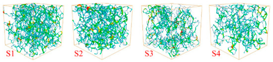
Figure 10.
Model of porous seepage channel: Connected pore models of samples S1, S2, S3 and S4 in Figure.
Table 4.
Statistical table of seepage channel.
Seepage microchannels were extracted via numerical simulation software to simulate the seepage path in the thickening process, as shown in Figure 11. The numerical simulation mentioned is carried out in the XLab module on Avizo software platform and the pores in the model are selected for absolute permeability simulation. The fluid flow in pores is simulated by Stokes equation, with pure water as the flow medium and density ρ = 1000 kg/cm3, viscosity μ = 0.001 Pa·s, the bottom boundary is the velocity inlet and the top boundary is the pressure outlet boundary, where the inlet pressure is 1.3 × 10⁵ Pa, the outlet pressure is 1.0 × 10⁵ Pa and the model size is 1 mm3. The combination of Darcy’s law, N-S equation and Stokes equation is used to establish the calculation model of absolute permeability, finally realize the simulation of absolute permeability and seepage in the pore and calculate the velocity of fluid in the pore. The fluid seepage was characterized through the changes in the density and color of flow lines and the fluid flow mainly occurred in the connected pores running through the influx boundary and outflow boundary of the model, with evident predominant flows. In addition, the greater the density values of the flow lines were, the larger the diameters of the pore channels were. The brighter the color was, the higher the flow velocity was. The seepage rate was high at the micropores, particularly when the pore channels shrunk and the dewatering rate rose sharply. Moreover, the maximum flow velocity usually appeared at small pores.
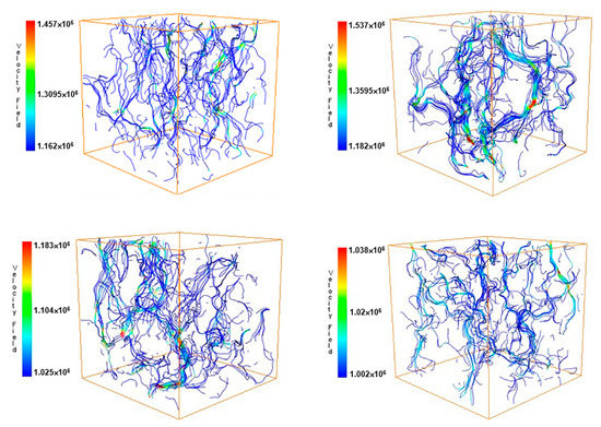
Figure 11.
Flow channel distributions of the seepage simulation.
Figure 11 shows that in the shear action, 0–500 high-speed flow paths passed these colored lines. From Stage I to Stage II, the flow lines became dense and concentrated at the upper-middle part of the sample, while few thin and short flow lines existed, indicating a good seepage effect. The maximum flow velocity inside the pores was 1.537 μm/s, which was elevated by 5.49% compared with the maximum flow velocity under the nonshear state. From Stage II to Stage IV, the flow lines were concentrated at the bottom and uniformly distributed. The flow lines at the middle part were reduced, whereas those at the bottom were enlarged. The flow lines running from bottom-up were greatly reduced and the maximum flow velocity was 1.038 μm/s. The main reason is that the sealed moisture was obviously drained in the dewatering process. Moreover, the pores were filled and finally extruded the seepage channels. Furthermore, the connectivity of the water-conducting channels declined.
4. Conclusions
- (1)
- The porosity of S1 without shear action was the maximum (46.48%) and it declined to 37.46% by 19.21% after the shear action was completed. The substantial drop of porosity mainly occurred from Stage II to Stage III. The moisture was drained upward along the channels formed in this stage. The tailings filled the pores downward and the underflow concentration was increased. The tailing flocs were displaced under the original circumstance of loose arrangement because of the shear action and then rearranged under the actions of gravity and mud layer pressure. The flocs were deformed and compacted to form a high-concentration underflow. The original macropores were extruded, deformed and segmented to form many micropores. Thus, the number of pores increased and the total porosity was reduced, accompanied by the runoff of overflow water.
- (2)
- In the corresponding PNMs, the balls in Stage I were large, whereas the sticks were small. The moisture was mainly stored in the former and water-conducting channels were formed in Stage II. The average coordination number of S2 was the maximum; with the best connectivity, the average stick radius was the maximum and many water-conducting channels were formed in Stage II. The shear force changed the network structure of flocs. Under the external shear force, large balls could easily evolve into several small balls to form isolated pores. In this case, the balls mainly stored water, whereas the sticks exerted the water-conducting effect. This finding indicates that under the shear action, the pores became loose, with poor connectivity and declining porosity.
- (3)
- In the seepage pore skeleton extraction model, the tortuosity of S2 declined by 0.75% compared with that of S1 under the non-shear state. The channel buckling degree of S2 was small and the average diameter of the channels at this moment was the maximum relative to the other three samples. The simulated flow lines of the seepage path in the thickening process showed that from Stage I to Stage II, the flow lines were densely distributed and concentrated at the upper-middle part of the sample. Moreover, few thin and short flow lines existed, manifesting a good seepage effect. The maximum flow velocity inside the pores was 1.537 μm/s, which was 5.49% higher than that under the nonshear state, mainly because the radius of the connected pores was enlarged by the bottom-up agglomeration of the wrapped macropore structures.
Author Contributions
Conceptualization, H.J. and Y.Y.; methodology, W.Z.; formal analysis, W.Z.; investigation, H.J., K.H. and J.Y.; writing—original draft preparation, W.Z.; writing—review and editing, H.J., Y.Y. and L.Y.; All authors have read and agreed to the published version of the manuscript.
Funding
This research was funded by the National Natural Science Foundation of China (No. 51834001).
Institutional Review Board Statement
Not applicable.
Informed Consent Statement
Not applicable.
Data Availability Statement
Data are contained within the article.
Conflicts of Interest
The authors declare no conflict of interest.
References
- Xiao, W.; Chen, W.Q.; Deng, X.Y. Coupling and coordination of coal mining intensity and social-ecological resilience in China. Ecol. Indic. 2021, 131, 108167. [Google Scholar] [CrossRef]
- Ma, Q.; Wu, J.G.; He, C.Y.; Fang, X.N. The speed, scale, and environmental and economic impacts of surface coal mining in the Mongolian Plateau. Resour. Conserv. Recycl. 2021, 173, 105730. [Google Scholar] [CrossRef]
- Worlanyo, A.S.; Li, J.F. Evaluating the environmental and economic impact of mining for post-mined land restoration and land-use: A review. J. Environ. Manag. 2020, 279, 111623. [Google Scholar] [CrossRef] [PubMed]
- Xi, Z.; Tang, S.; Wang, J. Pore structure and fractal characteristics of Niutitang shale from China. Minerals 2018, 8, 163. [Google Scholar] [CrossRef] [Green Version]
- Dong, L.J.; Tong, X.J.; Li, X.B. Some developments and new insights of environmental problems and deep mining strategy for cleaner production in mines. J. Clean. Prod. 2019, 210, 1562–1578. [Google Scholar] [CrossRef]
- Yari, M.; Bagherpour, R. Investigating an innovative model for dimensional sedimentary rocks characterization using acoustic frequencies analysis during drilling. Rud.-Geološko Naft. Zb. 2018, 33, 17–25. [Google Scholar] [CrossRef] [Green Version]
- Hu, Z.; Lu, S.; Klaver, J. An Integrated Imaging Study of the Pore Structure of the Cobourg Limestone—A Potential Nuclear Waste Host Rock in Canada. Minerals 2021, 11, 1042. [Google Scholar] [CrossRef]
- Qi, C.C.; Andy, F. Cemented paste backfill for mineral tailings management: Review and future perspectives. Miner. Eng. 2019, 144, 106025. [Google Scholar] [CrossRef]
- Yin, S.H.; Shao, Y.J.; Wu, A.X.; Wang, H.J.; Liu, X.H.; Wang, Y. A systematic review of paste technology in metal mines for cleaner production in China. J. Clean. Prod. 2020, 247, 126855. [Google Scholar] [CrossRef]
- Mamghaderi, H.; Aghababaei, S.; Gharabaghi, M.; Noaparast, M.; Albijanic, B.; Rezaei, A. Investigation on the effects of chemical pretreatment on the iron ore tailing dewatering. Colloids Surf. A 2021, 625, 126855. [Google Scholar] [CrossRef]
- Jiao, H.Z.; Wu, Y.C.; Wang, H.; Chen, X.M.; Li, Z.; Wang, Y.F.; Zhang, B.Y.; Liu, J.H. Micro-scale mechanism of sealed water seepage and thickening from tailings bed in rake shearing thickener. Miner. Eng. 2021, 173, 107043. [Google Scholar] [CrossRef]
- Toprak, N.A.; Altun, O. Considering hydrocyclone operation for tailings dewatering purpose and its effects on product specifications of paste backfill operations. Miner. Eng. 2021, 173, 107176. [Google Scholar] [CrossRef]
- Leidiane, G.R.; Roberta, S.O.; Thiago, N.P.; Luciana, S.S.; Elizabete, F.L.; Diógenes, R.L.; Elliott, A.; João, B.P. Using acrylamide/propylene oxide copolymers to dewater and densify mature fine tailings. Miner. Eng. 2016, 95, 29–39. [Google Scholar] [CrossRef]
- Krishna, R.S.; Quezada, G.R.; Sahu, J.K.; Sadangi, J.K. Rheological characterization and performance of flocculants in iron ore tailings management. Mater. Today Proc. 2021, 43, 2888–2894. [Google Scholar] [CrossRef]
- Zhu, Y.L.; Chae, M.; Wang, J.; Adhikari, B.; Mussone, P.; Bressler, D.C. Biowaste-based biodegradable flocculants for clean and sustainable tailings management in industrial mining and mineral processing. J. Clean. Prod. 2021, 323, 129195. [Google Scholar] [CrossRef]
- Yang, Y.; Wu, A.X.; Bern, K.; Wang, H.J. Effect of primary flocculant type on a two-step flocculation process on iron ore fine tailings under alkaline environment. Miner. Eng. 2019, 132, 14–21. [Google Scholar] [CrossRef]
- Rostami, N.Z.; Soares, J.B. Flocculation and dewatering of oil sands tailings with a novel functionalized polyolefin flocculant. Sep. Purif. Technol. 2021, 274, 119018. [Google Scholar] [CrossRef]
- Chen, Q.; Tao, Y.; Zhang, Q.; Qi, C. The rheological, mechanical and heavy metal leaching properties of cemented paste backfill under the influence of anionic polyacrylamide. Chemosphere 2022, 286, 131630. [Google Scholar] [CrossRef] [PubMed]
- Zhang, Q.; Li, Y.; Chen, Q. Effects of temperatures and pH values on rheological properties of cemented paste backfill. J. Cent. South Univ. 2021, 28, 1707–1723. [Google Scholar] [CrossRef]
- Ravi, N.; Farid, V.G.; Sean, S.R. Effect of shear on the yield stress and aggregate structure of flocculant-dosed, concentrated kaolinite suspensions. Miner. Eng. 2018, 123, 95–103. [Google Scholar] [CrossRef]
- Spehar, R.; Kiviti, M.A.; Fawell, P. Aggregate densification in the thickening of flocculated suspensions in an un-networked bed. Chem. Eng. Sci. 2015, 122, 585–595. [Google Scholar] [CrossRef]
- Li, S.; Wang, X.M.; Zhang, Q.L. Dynamic experiments on flocculation and sedimentation of argillized ultrafine tailings using fly-ash-based magnetic coagulant. Trans. Nonferr. Met. Soc. China 2016, 26, 1975–1984. [Google Scholar] [CrossRef]
- Xu, W.; Cao, P.; Tian, M. Strength Development and Microstructure Evolution of Cemented Tailings Backfill Containing Different Binder Types and Contents. Minerals 2018, 8, 167. [Google Scholar] [CrossRef] [Green Version]
- Deng, H.W.; Liu, Y.; Zhang, W.Y.; Yu, S.T.; Tian, G.L. Study on the Strength Evolution Characteristics of Cemented Tailings Backfill from the Perspective of Porosity. Minerals 2021, 11, 82. [Google Scholar] [CrossRef]
- Deng, H.W.; Duan, T.L.; Tian, G.L.; Liu, Y.; Zhang, W.Y. Research on Strength Prediction Model and Microscopic Analysis of Mechanical Characteristics of Cemented Tailings Backfill under Fractal Theory. Minerals 2021, 11, 886. [Google Scholar] [CrossRef]
- Salam, A.M.; Rmeci, B.; Simms, P.H. Determination of optimum polymer dosage for dewatering of oil sands tailings using torque rheology. J. Pet. Sci. Eng. 2020, 197, 107986. [Google Scholar] [CrossRef]
- Jiao, H.Z.; Chen, W.L.; Wu, A.X.; Yu, Y.; Ruan, Z.; Honaker, R.; Chen, X.; Yu, J. Flocculated unclassified tailings settling efficiency improvement by particle collision optimization in the feedwell. Int. J. Miner. Metall. Mater. 2021, 29. [Google Scholar] [CrossRef]
- Shriful, I.; David, J.W.; Marcelo, L.S.; Zhang, C.M. Settling, consolidation and shear strength behaviour of coal tailings slurry. Int. J. Min. Sci. Technol. 2020, 30, 849–857. [Google Scholar] [CrossRef]
- Rozalina, S.; Dimitrova, E.K. Factors affecting the shear strength of mine tailings/clay mixtures with varying clay content and clay mineralogy. Eng. Geol. 2012, 125, 11–25. [Google Scholar] [CrossRef]
- Yin, G.Z.; Zhang, Q.G.; Wang, W.S.; Chen, Y.L.; Geng, W.L.; Liu, H.R. Experimental study on the mechanism effect of seepage on microstructure of tailings. Saf. Sci. 2012, 50, 792–796. [Google Scholar] [CrossRef]
- Tian, J.; Ni, L.; Song, T.; Olson, J.; Zhao, J. An overview of operating parameters and conditions in hydrocyclones for enhanced separations. Sep. Purif. Technol. 2018, 206, 268–285. [Google Scholar] [CrossRef]
- Zhai, D.; Feng, B.; Guo, Y.T.; Zhou, X.T.; Wang, T.; Wang, H.H. Settling behavior of tungsten tailings using serpentine as flocculant. Sep. Purif. Technol. 2019, 224, 304–307. [Google Scholar] [CrossRef]
- Chen, F.B.; Xu, B.; Jiao, H.Z.; Chen, X.M.; Shi, Y.L.; Wang, J.X.; Li, Z. Triaxial mechanical properties and microstructure visualization of BFRC. Constr. Build. Mater. 2021, 278, 122275. [Google Scholar] [CrossRef]
- Jiao, H.; Wang, S.; Wu, A.; Shen, H.; Wang, J. Cementitious property of NaAlO2-activated Ge slag as cement supplement. Int. J. Miner. Metall. Mater. 2019, 26, 1594–1603. [Google Scholar] [CrossRef]
- Li, X.; Yang, S.; Wang, Y.; Nie, W.; Liu, Z. Macro-micro response characteristics of surrounding rock and overlying strata towards the transition from open-pit to underground mining. Geofluids 2021, 2021, 5582218. [Google Scholar] [CrossRef]
- Jiao, H.Z.; Wang, S.F.; Yang, Y.X.; Chen, X.M. Water recovery improvement by shearing of gravity-thickened tailings for cemented paste backfill. J. Clean. Prod. 2020, 245, 118882. [Google Scholar] [CrossRef]
- Dwari, R.K.; Angadi, S.I.; Tripathy, S.K. Studies on flocculation characteristics of chromite’s ore process tailing: Effect of flocculants ionicity and molecular mass. Colloids Surf. A 2018, 537, 467–477. [Google Scholar] [CrossRef]
- Bruna, C.T.; Sílvia, C.A. Performances of two flocculants and their mixtures for red mud dewatering and disposal based on mineral paste production. J. Clean. Prod. 2020, 257, 120534. [Google Scholar] [CrossRef]
- Pavičić, I.; Briševac, Z.; Vrbaški, A. Geometric and fractal characterization of pore systems in the Upper Triassic dolomites based on image processing techniques (example from Žumberak Mts, NW Croatia). Sustainability 2021, 13, 7668. [Google Scholar] [CrossRef]
- Wang, H.W.; Chao, L.; Wei, X.F.; Li, J.L.; Ji, C.; Wang, B.Z.; Qi, X.W.; Hu, P.C.; Ying, Y.F.; Tian, M.Q. Design of SiO2-TiO2-PAM composite flocculant with self-degrading characteristics and optimization of the flocculation process using a combination of central composite design and response surface methodology. Colloids Surf. A 2019, 583, 123982. [Google Scholar] [CrossRef]
- Cao, S.; Yilmaz, E.; Yin, Z.Y.; Xue, G.L.; Song, W.D.; Sun, L.J. CT scanning of internal crack mechanism and strength behavior of cement-fiber-tailings matrix composites. Cem. Concr. Compos. 2021, 116, 103865. [Google Scholar] [CrossRef]
- Shi, X.H.; Pan, J.N.; Pang, L.L. 3D microfracture network and seepage characteristics of low-volatility bituminous coal based on nano-CT. J. Nat. Gas Sci. Eng. 2020, 83, 103556. [Google Scholar] [CrossRef]
- Wei, C.; Derek, B.A.; Zhang, Y.H. Shear behavior of ultrafine magnetite tailings subjected to freeze-thaw cycles. Int. J. Min. Sci. Technol. 2019, 29, 608–615. [Google Scholar] [CrossRef]
Publisher’s Note: MDPI stays neutral with regard to jurisdictional claims in published maps and institutional affiliations. |
© 2022 by the authors. Licensee MDPI, Basel, Switzerland. This article is an open access article distributed under the terms and conditions of the Creative Commons Attribution (CC BY) license (https://creativecommons.org/licenses/by/4.0/).