Abstract
With the increasing penetration of the distributed generation and the growing variability of loads, flexible microgrids (FMGs) require operational strategies that can adapt to seasonal changes while maintaining reliable performance. To overcome the limitations of fixed-interval partition updates, this paper proposes a threshold-triggered dynamic operation strategy for FMGs. A composite partition-updating index is formulated by integrating an operation optimization index, which reflects network loss and hybrid energy storage (HES) cost, with a seasonal load uniformity index, so that partition reconfiguration is triggered only when scenario transitions significantly deteriorate operating performance. By enhancing seasonal load uniformity across partitions, the proposed framework reflects a symmetry-oriented operation philosophy for FMGs. An HES model is further established to coordinate short-term energy storage (STES) and long-term energy storage (LTES) across multiple timescales. In conjunction with remotely controlled switches (RCSs), the proposed framework enables adaptive adjustment of FMG boundaries and source scheduling under diverse seasonal conditions. A case study on the IEEE 123-bus distribution system demonstrates that the proposed strategy effectively reduces power fluctuations and redundant switching operations, improves seasonal load uniformity, and enhances both the operational flexibility and economic efficiency of FMGs.
1. Introduction
The significant increase in the penetration rate of the distributed generation presents challenges for the development of intelligent distribution networks [1,2,3]. These challenges include the burden of massive scheduling, reverse power flow, and power quality issues. In response, many future reform plans, such as the novel web of cells (WoC) [4] or honeycomb distribution network [5,6,7], have attracted considerable attentions in recent years as they can partition distribution networks with high penetrations of distributed generation into self-balancing microgrids by utilizing smart grid infrastructure. This reform offers several benefits: (1) It enhances the utilization rate of renewable resources by promoting on-site consumption, reducing reliance on centralized power generation. (2) The reform improves the power quality, which can regulate voltage levels, frequency, and power factor, ensuring stable and reliable power supply by microgrid partition operation. (3) The reliability of the distribution network is increased as each microgrid can operate independently in the event of faults or disruptions occurring in some microgrids, thereby enhancing overall resilience and minimizing localized outages. Motivated by the advantage and necessity microgrid partitioning, it is critical to plan and organize adequate microgrids under the background of the high penetration of distributed energy resources.
Usually, the flexible partitioning of a sub-microgrid requires several critical distribution facilities and resources for supporting regional autonomous operations. (1) Remote-controlled Switches (RCSs): In the distribution network, the line switches or sectioned switches could be reformed by intelligent mechanical devices and remote communication system for smart functionality [8]. With the seamless switching mode, the state of RCSs can be flexibly adjusted based on operational scenarios, enabling the system to dynamically expand or shrink the boundaries of sub-microgrids. (2) Controllable distributed generations (CDGs): These CDGs are composed of flexible resources, such as energy storage systems, distributed generations with the grid-forming converter or controllable loads. Different from non-controllable distributed generations (NDGs), these resources can serve as the primary power source of each sub-microgrid to provide the voltage and frequency support. By coordinately utilizing RCSs and CDGs, the boundaries and node outputs of sub-microgrid could be flexibly adjusted according to the operational requirements. This collaboration provides enhanced flexibility compared with strategies that only consider the dynamic performance of CDGs, which fosters the emergence of “flexible microgrids” (FMGs) [9,10,11,12].
For boundary-node collaboration FMG problems, in [13], the implementation of inverter-dominated dynamic microgrids in hybrid AC/DC distribution systems for the network reconfiguration is discussed. In [14,15], the Energy Storage Systems and RCSs are used and planned in the FMG with marine energy integration in response to contingencies. In [16], the soft open points are also used for the FMGs, which could further enhance the flexibility of the microgrid recovery during the disaster. However, most works done so far with respect to FMG operation focus on the flexible performance during the extreme weather scenarios, such as flood, hurricane, and earthquake, which could be regarded as abnormal scenarios in the distribution network operations. In fact, flexible performance is also significant in the normal scenarios if the static distribution network is reformed into FMGs, which has not been discussed yet. The existing technology, regarding the flexible strategies and performance of FMGs in abnormal scenarios, could not be directly applied to address the FMG operation under BSs (Basic Scenarios). The main challenges are summarized as follows:
- Most papers on FMGs aim to minimize outage loss to form dynamic islanding recovery areas in abnormal scenarios. However, during the normal scenarios, flexible strategies are also critical due to the frequent imbalance of generation-load or dynamic spatiotemporal migration of loads [17]. In different periods, the FMG should formulate the new boundary and node operational strategies to deal with the new scenarios. Thus, the models of FMGs should be reconsidered during the normal scenarios, especially their partition operational targets from different aspects.
- Continuously changing scenarios pose challenges for optimal operational objectives, the operators should update the boundary and resource operational strategies at different time periods [18]. The resources could form the fixed hour-level or minute-level time intervals to respond to system requirements. However, the frequency of boundary updates must be limited, as the types and lifespans of RCSs such as tie switches or sectionalizing switches do not permit updates with the same intervals as resource updates. Exceedingly short time intervals of boundary adjustments may significantly reduce switch lifespan, while overly long intervals pose challenges for capturing the system’s dynamics [19].
- The resources in the FMG are heterogeneous, particularly when considering CDGs, which exhibit varying adjustment capabilities and characteristics. CDGs could be categorized into two types: long-term energy storage (LTES) includes seasonal energy storage or hydropower, which can effectively meet the demand for energy transfer over a longer time span. Short-term energy storage (STES) composed of batteries or controllable loads, which can achieve effective suppression of power flow fluctuations over short timescales. Considering the distinctions between STES and LTES, the method that combines the characteristics of both needs to be thoroughly investigated [20].
To address the above challenges, we propose a dynamic FMG operation strategy that integrates switching and resource coordination to enhance operational flexibility under normal scenarios. From the perspective of symmetry, the proposed FMG operation strategy aims to maintain balanced load importance and stable partition structures across different seasonal scenarios, despite the inherent asymmetry introduced by fluctuating renewable generation and load migration. Table 1 compares the proposed approach with the current status of existing studies.

Table 1.
Comparative analysis of this study with relevant references.
The main contributions of this study are summarized as follows:
- The proposed approach jointly optimizes network loss minimization, power fluctuation suppression, and seasonal load uniformity, thereby enhancing both operational efficiency and equity in FMG operation.
- A dynamic operation framework for FMGs is established, in which partition updates are triggered only at scenario transitions. This reduces redundant switching actions and ensures stable operation within each scenario while retaining adaptability across scenarios.
- A coordinated model of STES and LTES is developed. STES is responsible for intra-day adjustments with limited switching frequency, whereas LTES provides inter-scenario balancing at the daily scale, thereby exploiting their complementary features to achieve multi-timescale regulation.
2. Microgrid Partition Operation Under Multi-Scenario
In this section, we introduce the dynamic operation of FMGs under multiple scenarios. During actual operation, partition-updating microgrids from scratch is impractical due to the frequent variations in renewable generation and load conditions. To ensure reliable and flexible operation, the microgrid must dynamically adjust its partitioning boundaries and coordination strategies according to scenario transitions. Here, the operational conditions are categorized into BS and Non-Basic Scenarios (NBSs). BS represent normal operating conditions characterized by daily and seasonal load fluctuations as well as NDG outputs, whereas NBS correspond to abnormal events such as extreme weather or disasters that may cause system faults or outages.
2.1. FMG Multi-Scenario Operation Framework
One of the key components of FMG is the RCS, which can be adjusted to respond to uncertain supply–demand scenarios, thereby enabling the dynamic expansion or contraction of sub-microgrid boundaries [21,22].
Another essential component of the FMG is the primary power source, which provides voltage and frequency support for each sub-microgrid. To accommodate seasonal operating scenarios, this study employs the hybrid energy storage (HES) system as the main source. The HES combines LTES and STES, thereby allowing its output to be flexibly modulated across different scenarios and time scales.
Figure 1 illustrates the multi-scenario operation framework for FMGs under BSs. Changes in RCS states typically occur at the transition between scenarios [23]. Taking the two BSs illustrated in Figure 1 as an example: at the end of Scenario 1 (time T), among the three RCSs, RCS1 and RCS3 are open while RCS2 is closed, forming three sub-microgrids. At the scenario transition, the partition-updating index threshold is triggered, as fluctuations in distributed generation outputs and loads aggravate voltage and power-flow limit violations under the original partitioning. When switching to Scenario 2, at its initial time step (time 1), RCS1 and RCS2 are open while RCS3 is closed—thereby updating the partition configuration to mitigate fluctuation-induced issues within the affected areas. The key aspects of this framework are as follows:
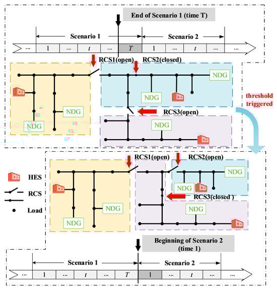
Figure 1.
Multi-scenario operation framework of FMG.
- (1)
- Because the partition-updating index is computed from the operating status of FMGs over all time steps within a scenario, partition updates can occur only at the initial instant of a scenario transition. Within a given scenario, the RCS states remain fixed, while the HES units perform dynamic regulation.
- (2)
- A scenario transition does not necessarily trigger a partition update. Only when the partition-updating index evaluated at the end of the preceding scenario exceeds the prescribed threshold will the optimal partition for the next scenario be computed, with the corresponding RCS/HES actions executed to implement the update.
- (3)
- The placement of RCSs must comply with the “one partition corresponds to one HES” principle; that is, regardless of partition updating, the regional assignment of each HES remains fixed.
Synthesizing the above, the proposed FMG multi-scenario operation framework offers the following advantages:
- (1)
- Comprehensive scenario adaptability. Driven by multiple basic scenarios, the framework accommodates routine load fluctuations, seasonal variations, and the uncontrollable outputs of common distributed generation.
- (2)
- High scalability. Area boundaries are defined by RCSs whose locations are fixed while their states are adjustable. In large FMGs, RCSs can be installed in the vicinity of existing partition switches, avoiding the siting ambiguities that arise in large networks.
- (3)
- Dynamic partition updating. The framework evaluates full-horizon operations within each scenario and computes a partition-updating index at the scenario end to decide whether an update is needed, thus minimizing the associated operational costs.
2.2. Rationality Analysis of Hybrid Energy Storage Replacing CDG
In general, the islanding management center of each islanded area designates a CDG as the primary source because it can adjust its output power and voltage in real time, making it well suited to serve small-area loads. However, typical CDGs have a limited regulation range and operate mainly in the forward direction. When an area hosts numerous NDGs and their output fluctuations peak simultaneously, damping the resulting power-flow oscillations requires replacing the CDG with a resource that provides strong bidirectional regulation capability—that is, robust adjustment across both export and import ranges.
In this study, an HES model is employed as the primary source in each partition to provide voltage and frequency support. Owing to the flexible power-regulation capability of STES and the effective long-timescale energy shifting of LTES, HES is well suited for dynamic regulation during FMG operation [24]. In this section, STES is configured to enable intra-day energy exchange, while LTES facilitates energy exchange across different typical days.
3. Dynamic Operation of Microgrid Based on Partition Update
In practical microgrid operation, routine load fluctuations under BSs and the inherent uncertainty of renewable generation pose persistent challenges to maintaining balance within the FMG. These variations necessitate timely reconfiguration of RCS switching states and coordinated HES scheduling. Accordingly, in this section, we propose a dynamic FMG operation framework driven by a composite partition-updating index. This section formulates the comprehensive optimization index, introduces the seasonal load uniformity index, and establishes the HES operational model that jointly supports multi-scenario boundary reconfiguration and resource dispatch.
3.1. FMG Multi-Scenario Comprehensive Partition-Updating Index and Dynamic Operation Strategies
In the FMG defined herein, inter-scenario differences are manifested primarily in fluctuations of loads and NDG outputs. Their stochasticity is not modeled explicitly; instead, representative load profiles and NDG profiles under typical scenarios are used directly. To capture different scenarios, we introduce a composite multi-scenario partition-updating index for the FMG. The composite index serves two purposes:
- (1)
- At the end of each scenario, the accumulated partition-updating index is computed. If it exceeds a prescribed threshold, a partition update is triggered.
- (2)
- For scenarios that require reconfiguration, the composite partition-updating index is adopted as the objective function for the expected operation in the subsequent scenario, guiding the joint planning of RCS switching states and HES outputs to maintain the optimal partition configuration.
3.1.1. Comprehensive Optimization Index
To balance the operational efficiency and economic performance of AC/DC hybrid distribution networks, this study integrates the network loss index and the total HES cost index into a unified model, and constructs a comprehensive optimization index , as shown in (1) and (2):
where and denote the network loss and HES cost of the -th sub-microgrid under scenario bs. (i,j) represents the line set in the sub-microgrid. is the line resistance. is the line current. denotes the equivalent cost coefficient of unit g. represents its active power output.
By summing up the line losses and the total HES costs, the comprehensive optimization index can be obtained. A smaller value indicates more efficient and economical operation of the distribution network.
3.1.2. Seasonal Load Uniformity Index
In practical regional partitioning, it is often necessary to classify and plan seasonal load types. Figure 2 presents a schematic division of loads according to their seasonal importance. The characteristics of various load categories vary considerably throughout the year. According to the principle of grouping loads with similar importance levels within the same area, consider Scenario 1 (Winter Holiday/Spring Festival) as an example. During this period, schools and factories are generally closed, giving them the lowest importance. Residential areas carry a high proportion of heavy loads in winter, while shopping malls face peak demand during holidays; both are therefore assigned relatively high importance. Hospitals maintain consistently high importance throughout the year, but their importance reaches its maximum in winter—when infectious diseases spread more easily—and during the Spring Festival, when population mobility is elevated [25].
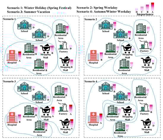
Figure 2.
Schematic diagram of load importance partitioning under different scenarios.
Based on this rationale, the seasonal load uniformity index is defined to measure the seasonal variability in the importance of different load types. The objective is to cluster loads with similar seasonal importance within the same area as much as possible, so that fluctuations in daily load patterns can be more effectively managed and coordinated. For example, considering Scenario 1 in Figure 2, if hospitals and residential areas—both characterized by relatively high importance during this period—are grouped within the same partition, the seasonal load uniformity index tends to be low, indicating a more homogeneous importance distribution. In contrast, if a residential area and a shopping mall are grouped together with a factory whose importance is relatively low during the winter holiday, the resulting partition exhibits a higher seasonal load uniformity index, reflecting a more heterogeneous distribution of load importance. For the s-th sub-microgrid under scenario bs, the seasonal load uniformity index is defined as in (3):
where denotes the importance index of the load at node i. It is a continuous variable defined within the interval (0,1), where the larger values indicate higher importance.
Combining the above indices and considering the rationality of partition updating, the proposed composite partition-updating index system is expressed as in (4):
where denotes the composite partition-updating index. and are weighting coefficients.
3.1.3. FMG Multi-Scenario Dynamic Operation Strategy
The multi-scenario dynamic operation strategy of the FMG is illustrated in Figure 3. Within each scenario, fluctuations in loads and NDGs are quantified, and the corresponding partition-updating index of that scenario is computed. If this index exceeds a preset threshold, the FMG automatically optimizes a more suitable operation scheme for HES and a partition scheme for RCS. These adjustments are then executed to restore stable operation of the area under the given scenario.
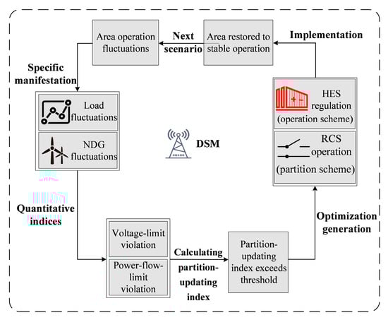
Figure 3.
FMG multi-scenario dynamic operation strategy.
3.2. FMG Multi-Scenario Operation Model
Based on the FMG multi-scenario operation framework and the partition-updating index established earlier, we next construct the FMG multi-scenario operation model. The partition-updating index is adopted as the optimization objective. This model determines the optimal RCS switching states and HES outputs across two adjacent scenarios to minimize the partition-updating index in the subsequent scenario.
Unlike fixed scenarios and time periods, this operation model is defined under varying scenarios and time horizons. Therefore, most constraints are expressed with respect to scenario and time.
3.2.1. Partitioning Constraints Under the Basic Scenario
Firstly, each node must belong to one and only one sub-microgrid:
where is the sub-microgrid belonging variable, which is a binary variable. If node i belongs to sub-microgrid s, then ; otherwise, .
Secondly, each sub-microgrid must be assigned one and only one HES as the main source for voltage and frequency support:
where is the location parameter of HES. If HES k is located at node i, then . Otherwise, . The HES location is predefined in this paper, so the value of is fixed.
Each line is assigned to a sub-microgrid, where the line belonging variable is:
where is the line belonging variable. If a line belongs to a sub-microgrid, . Otherwise, .
Finally, sub-microgrids operating in the islanded mode must remain disconnected from the lines of neighboring sub-microgrids:
where denote the binary line variable that could be used to indicate whether the line is switched on or off. If the line is included in a sub-microgrid, then ; if disconnected, then . The switching status of a line is determined by the sum of its partition variables across all sub-microgrids.
3.2.2. RCS Operation Constraints
Let be the location parameter of RCSs, if the -th RCS is installed, then ; otherwise, :
If the line is not equipped with an RCS, then means that the line remains switched off regardless of scenario changes.
3.2.3. STES Constraints
STES operation is highly flexible and enables short-term adjustment of the charging and discharging states. The operating model of STES is defined by (10)–(13):
where and , denote the STES energy level and charging/discharging power at time t of scenario bs. is a binary state variable that determines the operating mode of STES, where = 1 indicates the charging state and = 0 indicates the discharging state. Parameters and represent the charging and discharging efficiencies, respectively. is the rated capacity, the power-to-capacity ratio, and the time step, which is set to 1 h.
As illustrated in Figure 4, STES operation is highly flexible, enabling short-term regulation without the need to consider inter-scenario differences.
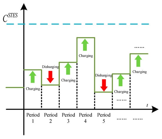
Figure 4.
STES operation strategy.
3.2.4. LTES Constraints
As illustrated in Figure 5, unlike STES, the physical characteristics of LTES imply that its self-discharge rate is nearly zero. At the transition between two adjacent typical days, the initial state of the next scenario must account for the cumulative charging and discharging of the previous scenario.
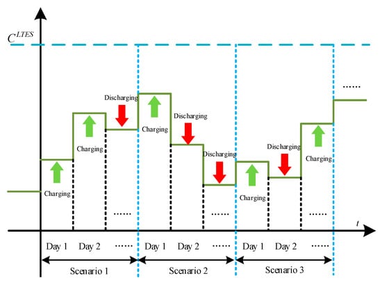
Figure 5.
LTES operation strategy.
Therefore, the operating model of LTES can be expressed by (14)–(18):
where constraint (14) describes the capacity of LTES at all time steps except the initial time of the first scenario. represents the LTES self-discharge rate. Constraint (15) specifies the maximum charging and discharging power constraints, where and denote the LTES charging/discharging active power. Binary variables and indicate the charging and discharging states of LTES at time t. denotes the rated capacity. Constraint (16) represents the energy of LTES in BS, whose initial value is the cumulative energy from the previous scenario’s charge and discharge power minus the energy loss caused by self-discharge, while the remaining time steps follow the same rule as in (14). Here, denotes the occurrence probability of a typical day, and multiplying by 365 yields the expected number of annual occurrences. denotes the maximum number of scenarios. Constraint (17) expresses that the final scenario is equal to the initial scenario with a range of 8760 h. (18) constrain the binary variables and to ensure that the LTES can only be charging or discharging during each typical day.
3.2.5. HES Operating Constraints
Building upon the mathematical models of STES and LTES, and since HES is composed of both, in this study each sub-microgrid is configured with an HES node. The active and reactive power outputs of each HES node, together with those of its corresponding STES and LTES components, must satisfy:
where constraint (19) establishes the relationship between the charging/discharging power of HES and that of its corresponding STES and LTES units. Specifically, and denote the charging and discharging power of HES. Constraints (20) and (21) define the charging/discharging limitations of STES and LTES, respectively. Constraint (22) specifies the relationship between the active/reactive power outputs of all charging/discharging units and their rated capacities.
3.2.6. Power Flow Constraints
The second-order cone model of power flow constraints is adopted in this paper. Our previous work has already addressed the partitioned power flow constraints in detail; interested readers are referred to that work for the specific derivations and formulations [26].
4. Dynamic Operation Process of Microgrids Considering Threshold-Triggered Updates
Based on Section 2, a microgrid dynamic operation process is designed to adapt to the framework. The flowchart of this process is shown in Figure 6.
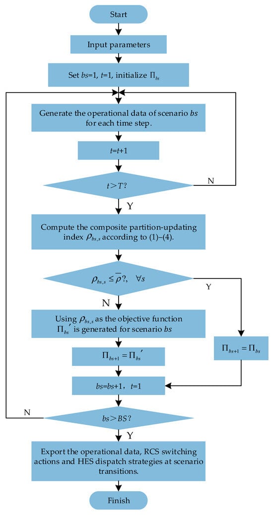
Figure 6.
FMG dynamic operation flowchart.
The explanation of this flowchart is as follows:
- The initial partition configuration at the starting time of the first scenario is fixed. Only at the transition between scenarios will RCS operations cause changes in the partition configuration.
- denotes the trigger threshold for partition updating. represents the actual partition configuration under scenario , while represents the theoretical optimal partition configuration of scenario .
- At the end of each scenario, the composite partition-updating index for all regions can be calculated. If in all regions is less than or equal to the threshold , the partition configuration remains unchanged, . If any region has greater than the threshold, the partition configuration is updated, .
- The value of the threshold is adjustable and is determined based on engineering experience, and can be adjusted according to different operational requirements. In practical applications, the threshold can be flexibly adjusted by system operators according to their operational preferences, such as switching lifetime constraints or performance requirements.
5. Case Study
In the improved IEEE 123-bus distribution system, the FMG dynamic operation process proposed in this paper is tested. The simulation environment is based on Python 3.14.2, with additional package Numpy 2.3.5, pandas 2.3.3 and hardware configuration of Intel Core i7-4600U, 2.1 GHz CPU, 8 GB RAM, and a 64-bit operating system PC. The solver employed is Gurobi 10.0.2 [27] and Gurobi’s parameters are the default. By reformulating the absolute-value expressions into equivalent sets of linear inequality constraints, the originally nonlinear constraints can be converted into linear ones, thereby transforming the problem into a mixed-integer second-order cone programming (MISOCP) model.
Considering that the number of nodes in each partition should neither be excessively large nor too small, the total number of partitions is set to 9 and the number of sub-microgrids remains unchanged. The initial partition configuration is shown in Figure 7.
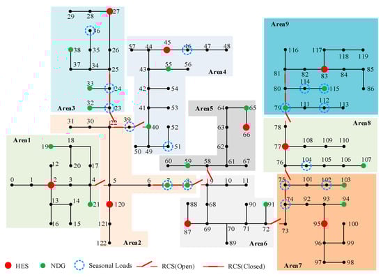
Figure 7.
Schematic diagram of the IEEE 123-bus distribution system and its initial partition configuration.
From Figure 7, it can be observed that compared with the original IEEE 123-bus distribution system, the improved IEEE 123-bus distribution system introduces RCSs at selected branches to enable partition updating. One HES is assigned to each partition as the main power source, deployed at nodes 2, 27, 45, 66, 77, 83, 87, 95 and 120. Each sub-microgrid is indexed from 1 to 9, with its corresponding HES node number marked in Figure 7. In addition, NDGs and seasonal loads are assigned to specific boundary nodes.
The locations of RCSs are also indicated to ensure that their operation does not alter the total number of sub-microgrids, and that each sub-microgrid contains at least one HES. Generally, RCSs are not placed across HES nodes.
According to the seasonal scenario objectives of this study, the system is divided into four scenarios corresponding to the four seasons (spring, summer, autumn, and winter), with scenario indices ranging from 1 to 4. Each scenario represents a typical day with a time sequence divided into 24 hourly intervals, resulting in a total of 96 time steps across the four scenarios.
5.1. Practical Parameter Settings
5.1.1. Scenario-Based Parameters
The primary distinctions between scenarios are reflected in the seasonal load importance index, the NDG output curves, and the HES-related scenario parameters. Since all HES-related scenario parameters are modeled as operational variables, they can be generated during the optimization process and therefore do not require explicit prior specification.
The importance indices of seasonal load nodes for each scenario are presented in Table 2.
Table 2.
Importance indices of seasonal load nodes.
For simplification, it is assumed that the NDG outputs at all NDG nodes have identical power outputs. The output curves of NDGs under the four scenarios are illustrated in Figure 8.
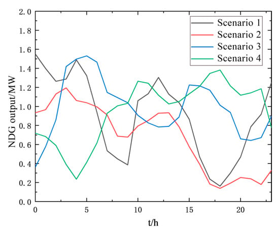
Figure 8.
NDG output curves in four scenarios.
5.1.2. HES Parameters
The parameters of HES include all static parameters of its components, STES and LTES, as presented in Table 3. In practical operation, these parameters are treated as the basic constants of HES and remain unchanged, in contrast to operational variables such as , , , , , , which are generated and updated dynamically during model operation.
Table 3.
Static parameters of HES.
5.2. Comparison of Partition Update with and Without Threshold Consideration
Since, at the end of each scenario, there is always the possibility that certain regional indices may exceed the threshold, partition updates could potentially occur in all four scenarios. As a benchmark comparison, we also consider a situation in which the threshold mechanism is disabled, equivalent to setting the trigger threshold to infinity. Under this condition, the system will always maintain the initial partition configuration across all four typical scenarios, as shown in Figure 7.
5.2.1. Indicators and Partitions of Each Scenario and Region with Partition Update
We first evaluate the case where partition updates are considered, with the trigger threshold set to . Assuming that the comprehensive optimization index carries greater weight than the seasonal load uniformity index, the weighting coefficients are set as and .
The comprehensive partition update indices for each region at the end of Scenario 1 are shown in Table 4.
Table 4.
Comparison of comprehensive partition update indices and thresholds at the end of scenario 1.
According to Table 3, Region 3, Region 6, and Region 8 exceed the threshold, thereby triggering partition updates. The corresponding optimal partition configuration is realized through RCS operations, resulting in the updated partition configuration for Scenario 2.
The comprehensive partition update indices at the end of Scenario 2 are shown in Table 5.
Table 5.
Comparison of comprehensive partition update indices and thresholds at the end of scenario 2.
As shown in Table 5, Region 2 and Region 9 exceed the threshold, again triggering partition updates. The corresponding optimal partition configuration is realized via RCS operations, and the updated configuration becomes the configuration for Scenario 3.
At the end of Scenario 3, the comprehensive partition update indices for each region and their comparison with the threshold are presented in Table 6.
Table 6.
Comparison of comprehensive partition update indices and thresholds at the end of scenario 3.
As illustrated in Table 6, none of the regional indices exceed the threshold in Scenario 3. Consequently, no partition updates are triggered, and the partition configuration in Scenario 4 remains identical to that of Scenario 3.
At the end of Scenario 4, the comprehensive partition update indices and their comparison with the threshold are summarized in Table 7.
Table 7.
Comparison of comprehensive partition update indices and thresholds at the end of scenario 4.
In Scenario 4, Region 2, Region 7, and Region 8 exceed the threshold, which triggers partition updates. The corresponding optimal partition configuration is implemented via RCS operations.
Considering the cyclic nature of the four scenarios, the resulting partition configuration of Scenario 4 is applied as the initial configuration for the next annual cycle. The structural changes and transition process across the four scenarios are illustrated in Figure 9, Figure 10 and Figure 11.
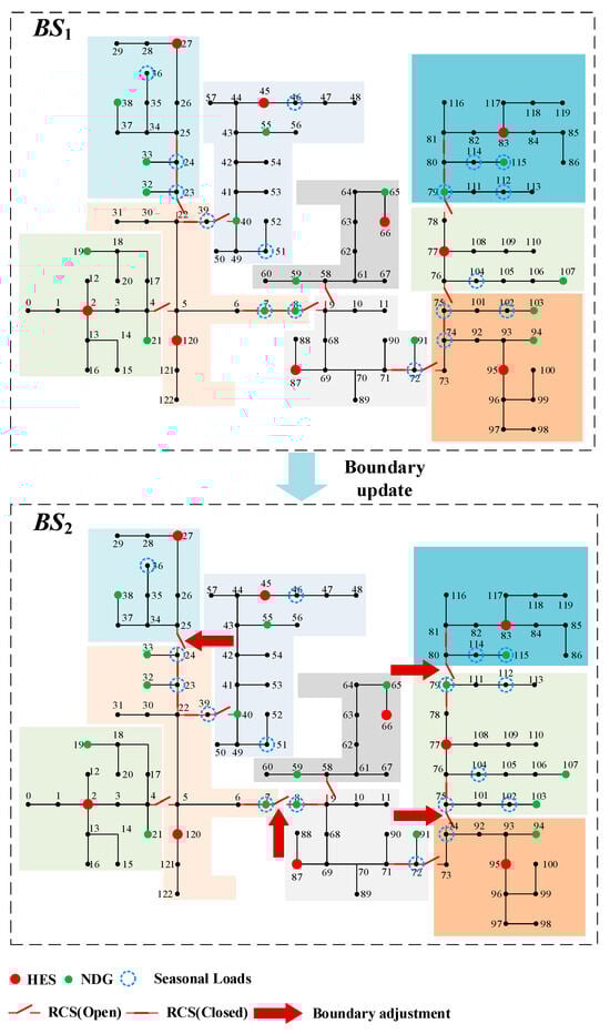
Figure 9.
Overall partition configuration under BS1 and BS2.
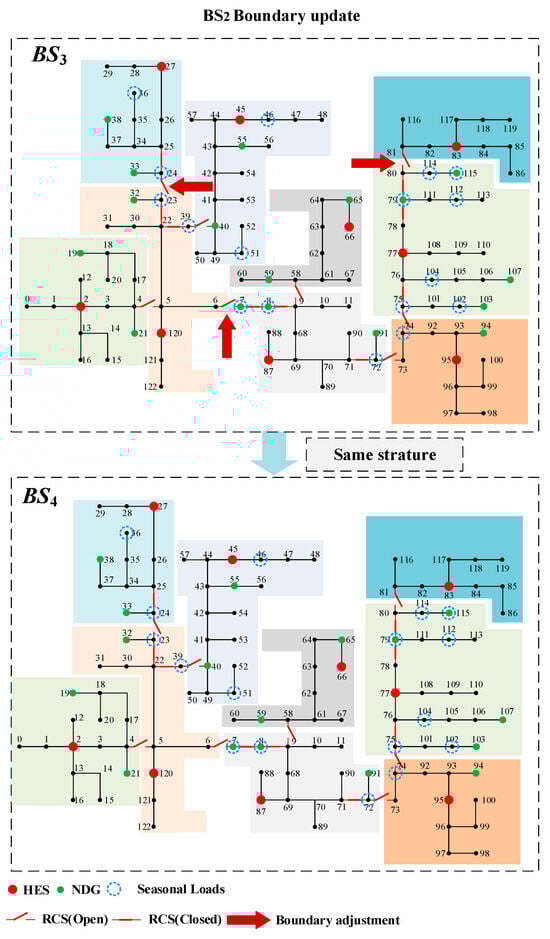
Figure 10.
Overall partition configuration under BS3 and BS4.
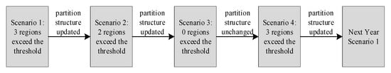
Figure 11.
Simple diagram of partition configuration change process under four scenarios.
From the above figure, the following conclusions can be drawn:
- (1)
- Due to the presence of seasonal loads and the fluctuations of NDG outputs, the switching between seasonal scenarios can lead to certain regional indices exceeding the threshold, thereby triggering partition updates.
- (2)
- The increase in partition indices during updates is mainly attributed to NDGs and seasonal loads located at regional boundaries. When the output differences of NDGs between adjacent scenarios are significant, the resulting local power fluctuations become pronounced. Similarly, the importance indices of seasonal loads may increase substantially in certain scenarios. As a result, regions with higher average importance indices tend to expand to include more nodes, whereas other regions with reduced importance indices may shrink accordingly, reflecting the dynamic reallocation effect.
5.2.2. Comparison of Regional Indices with and Without Partition Update
To further verify the overall effectiveness of the proposed dynamic partition update method, this subsection compares the regional indices under two conditions: considering partition updates and without considering partition updates.
When partition updates are not considered, the system maintains its initial partition configuration across all four scenarios. Each scenario is divided into 96 time steps, and each of the 9 sub-microgrids has a corresponding comprehensive partition-updating index for each time step. The comparison of indices between the two approaches is presented in Table 8 and is illustrated in Figure 12.
Table 8.
Comparison of comprehensive partition update index at the end of each scenario under two operation modes.
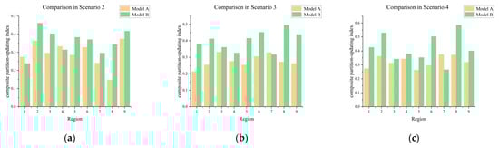
Figure 12.
Comparison of composite partition-updating index at the end of each scenario under two operation modes: (a) Scenario 2; (b) Scenario 3; (c) Scenario 4.
The advantages of considering partition updates can be clearly observed. Except for Scenario 1 where the indices remain the same, in the other three scenarios the indices are significantly reduced under the update strategy. The reconfiguration of regions driven by RCS operations, combined with the charging and discharging of HES, allows the system to better smooth the output fluctuations of NDG. This effect is particularly evident in Regions 2, 3, 6, 7, 8, and 9, where the indices exceed the threshold.
The most significant optimization occurs in Region 2 and Region 8. In Scenario 2, the indices of Region 2 decreased by 21.0% compared with the case without updates, while in Scenarios 3 and 4, the indices of Region 2 decreased by 38.1% and 31.7%. Similarly, in Scenarios 2–4, the indices of Region 8 decreased by 56.9%, 45.1%, and 36.6%, respectively.
The underlying reason is that Region 2 and Region 8 are located at the intersection of NDG nodes and seasonal load nodes, where more RCS are placed compared with other regions. With more RCS adjustments available, the adjustment range of NDG against seasonal load fluctuations becomes larger. This directly enhances the flexibility of the regions, meaning that the internal oscillations of these regions are better suppressed through increased adjustment margins.
5.2.3. Operation of HES Considering Partition Updates
Under the operation of 9 regions across 96 time periods, the internal main power source HES achieves peak shaving and valley filling effects for the fluctuations of NDG through charging and discharging. Taking the HES in Region 2, which had the greatest improvement in index optimization analyzed in the previous section, as examples, the charging/discharging power of STES and LTES and their corresponding stored energy curves are shown in Figure 13 a (STES) and Figure 13b (LTES).
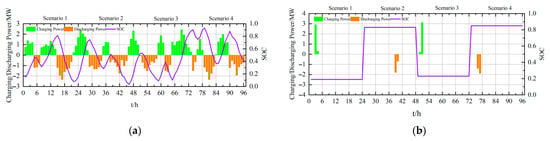
Figure 13.
The charging and discharging power and energy storage value curves of STES and LTES in area 2: (a) STES; (b) LTES.
From the above figure, the following conclusions can be drawn:
- (1)
- STES is used for continuous, real-time regulation within a single day, where charging and discharging behaviors occur at each time interval within the scenario, and the charging/discharging power fluctuates frequently. LTES, on the other hand, is used for long-term inter-day energy compensation, typically undergoing only one charge or discharge process within a single scenario. This actual operational logic is consistent with the theoretical strategy illustrated in Figure 4 and Figure 5.
- (2)
- Taking Scenario 3 in Region 2 as an example: during 11:00–13:00, the NDG output is relatively high, STES remains in a charging state to “absorb” the surplus NDG output; during 14:00–16:00, when NDG output is lower, STES shifts to a discharging state to “compensate” for the insufficient NDG supply. In other periods, when NDG output fluctuates significantly, STES appropriately adjusts charging/discharging power to maintain power flow balance. Similar analyses apply to other regions and scenarios.
- (3)
- In general, due to the intrinsic characteristics of LTES, its charging/discharging behavior under continuous daily scenarios is often alternating, i.e., “charge–discharge–charge–discharge...”. Taking Region 2 as an example: LTES alternates between charging and discharging during Scenarios 1–4, and its stored energy reaches a maximum at the initial moment of Scenario 4, while being at a minimum at the initial moment of Scenario 1.
5.2.4. Calculation Time and Scalability
The proposed optimization framework is formulated as a MISOCP model and solved using Gurobi Optimizer. All simulations are conducted on a desktop computer which configuration is listed above. In the case study, the computational time required to solve the optimization problem for each scenario is approximately 14 s, indicating that the proposed method can be efficiently applied for scenario-level offline operation analysis.
In terms of the scalability, the computational burden of the proposed framework is mainly influenced by the number of partitions, RCSs, HES, and the total number of network nodes. The proposed framework is scalable to larger distribution systems with comparable partition configurations. Further improvements in computational efficiency and large-scale applications will be investigated in future work.
6. Conclusions
This paper proposes a FMG dynamic operation strategy based on a composite partition-updating index. Instead of relying on fixed-time or always-on reconfiguration strategies, a threshold-triggered partition updating method was introduced to adapt microgrid boundaries and resource scheduling only when operating performance deteriorates at the end of a scenario.
The case study on the IEEE 123-bus distribution system demonstrates that the proposed strategy effectively reduces regional partition-updating indices in most scenarios, suppresses the impact of seasonal load migration and NDG fluctuations, and avoids redundant switching operations. The results indicate that the proposed framework is suitable for offline operation analysis and decision support in flexible microgrids with seasonal operating characteristics.
From a practical perspective, the proposed strategy is intended to support system operators in planning and operational decision-making under seasonal transitions. By providing a quantitative criterion to determine whether partition boundaries should be updated at scenario transitions, the proposed method helps operators balance operational performance improvements against the cost and lifetime constraints of RCSs. In practical applications, the threshold value and weighting coefficients can be adjusted according to local operational preferences, such as prioritizing switching reduction or improving load importance balance in specific regions. As the method operates at the scenario level and does not require real-time control, it can be integrated into offline analysis tools to assist operators in formulating adaptive partitioning and resource scheduling strategies for flexible microgrids.
Despite the effectiveness demonstrated in the case study, several limitations of this work should be acknowledged. First, this study does not explicitly model heterogeneous DG types, which may affect partition update behaviors and storage coordination. Second, the number of partitions is fixed in the case study to focus on validating the proposed strategy. Future work will focus on heterogeneous DG modeling and the joint optimization of partition number and resource allocation in more complex operating environments.
Author Contributions
Conceptualization, W.J., X.G., Y.D. and M.L.; methodology, W.J., X.G., J.S. and Y.D.; software, Y.D. and J.S.; validation, X.T., J.S. and M.X.; writing—original draft preparation, X.G. and M.L.; writing—review and editing, Y.D.; visualization, X.G. and M.L.; supervision, W.J.; project administration, W.J.; funding acquisition, W.J. All authors have read and agreed to the published version of the manuscript.
Funding
This research was funded by the Headquarters Technology Project of State Grid Hubei Electric Power Co., Ltd., grant number No. 5400-202422220A-1-1-ZN.
Data Availability Statement
The original contributions presented in the study are included in the article, further inquiries can be directed to the corresponding author.
Conflicts of Interest
Authors Jinli Sun, Manjia Liu, Xuan Tong and Muchao Xiang were employed by State Grid Hubei Electric Power Research Institute. The authors declare that this study was funded by the Head-quarters Technology Project of State Grid Hubei Electric Power Co., Ltd. (No. 5400-202422220A-1-1-ZN). The funder had the following involvement with the study: study, design, collection, analysis, interpretation of data and the writing of this article.
Abbreviations
The following abbreviations are used in this manuscript:
| FMG | Flexible microgrid |
| HES | Hybrid energy storage |
| STES | Short-term energy storage |
| LTES | Long-term energy storage |
| RCS | Remotely controlled switch |
| NDG | Non-controllable distributed generation |
| CDG | Controllable distributed generation |
| BS | Basic scenarios |
| NBS | Non-basic scenarios |
References
- Firouz, Y.; Farhadi-Khani, S.; Lobry, J.; Vallée, F.; Khakpour, A.; Durieux, O. Numerical comparison of the effects of different types of distributed generation units on overcurrent protection systems in MV distribution grids. Renew. Energy 2014, 69, 271–283. [Google Scholar] [CrossRef]
- Sun, S.; Lei, Y.; Hao, G.; Lu, Y.; Liu, J.; Song, Z.; Zhang, J. Transient damping of virtual synchronous generator for enhancing synchronization stability during voltage dips. CES Trans. Electr. Mach. Syst. 2024, 8, 143–151. [Google Scholar] [CrossRef]
- Conti, S. Analysis of distribution network protection issues in presence of dispersed generation. Electr. Power Syst. Res. 2009, 79, 49–56. [Google Scholar] [CrossRef]
- Martini, L. Trends of smart grids development as fostered by European research coordination: The contribution by the EERA JP on smart grids and the ELECTRA IRP. In Proceedings of the IEEE 5th International Conference on Power Engineering, Energy and Electrical Drives (POWERENG), Riga, Latvia, 11–13 May 2015; pp. 23–30. [Google Scholar]
- Ji, H.; Wang, C.; Li, P.; Zhao, J.; Song, G.; Ding, F.; Wu, J. An enhanced SOCP-based method for feeder load balancing using the multi-terminal soft open point in active distribution networks. Appl. Energy 2017, 208, 986–995. [Google Scholar] [CrossRef]
- Liu, N.; Yu, X.; Wang, J.; Xue, Y. Optimal operation of power distribution and consumption system based on ubiquitous internet of things: A cyber-physical-social system perspective. Autom. Electr. Power Syst. 2020, 44, 1–12. [Google Scholar]
- Jia, H.; Mu, Y.; Hou, K. Morphology evolution and operation regulation of urban energy system from perspective of energy transition. Autom. Electr. Power Syst. 2021, 45, 49–62. (In Chinese) [Google Scholar]
- Lei, S.; Wang, J.; Hou, Y. Remote-controlled switch allocation enabling prompt restoration of distribution systems. IEEE Trans. Power Syst. 2018, 33, 3129–3142. [Google Scholar] [CrossRef]
- Gharibvand, H.; Gharehpetian, G.B.; Anvari-Moghaddam, A. A survey on microgrid flexibility resources, evaluation metrics and energy storage effects. Renew. Sustain. Energy Rev. 2024, 201, 114632. [Google Scholar] [CrossRef]
- Debouza, M.; Al-Durra, A.; El-Fouly, T.H.M.; Zeinedin, H.M.H. Survey on microgrids with flexible boundaries: Strategies, applications, and future trends. Electr. Power Syst. Res. 2022, 205, 107765. [Google Scholar] [CrossRef]
- Su, Y.; Li, D.; Wang, F.; Olama, M.; Ferrari, M.; Ollis, B.; Liu, Y. Flexible dynamic boundary microgrid operation considering network and load unbalances. Appl. Energy 2024, 371, 123633. [Google Scholar] [CrossRef]
- Ma, Y.; Hu, X.; Yin, H.; Zhu, L.; Su, Y.; Wang, F.; Tolbert, L.M.; Liu, Y. Real-time control and operation for a flexible microgrid with dynamic boundary. In Proceedings of the IEEE Energy Conversion Congress and Exposition (ECCE), Portland, OR, USA, 23–27 September 2018; pp. 5158–5163. [Google Scholar]
- Wang, P.; Liu, X.; Jin, C.; Loh, P.C.; Choo, F.H. A hybrid AC/DC micro-grid architecture, operation and control. In Proceedings of the IEEE Power and Energy Society General Meeting, Detroit, MI, USA, 24–28 July 2011. [Google Scholar]
- Yang, X.; Zhou, Z.; Zhang, Y.; Liu, J.; Wen, J.; Wu, Q.; Cheng, S. Resilience-oriented co-deployment of remote-controlled switches and soft open points in distribution networks. IEEE Trans. Power Syst. 2023, 38, 1350–1365. [Google Scholar]
- Wu, X.; Liu, J.; Men, Y.; Chen, B.; Lu, X. Optimal energy storage system and smart switch placement in dynamic microgrids with applications to marine energy integration. IEEE Trans. Sustain. Energy 2023, 14, 1205–1216. [Google Scholar]
- Ma, L.; Wang, L.; Liu, Z. Soft open points-assisted resilience enhancement of power distribution networks against cyber risks. IEEE Trans. Power Syst. 2023, 38, 31–41. [Google Scholar] [CrossRef]
- Shi, W.; Liang, H.; Bittner, M. Dynamic microgrid formation for resilient distribution systems considering large-scale deployment of mobile energy resources. Appl. Energy 2024, 362, 122978. [Google Scholar] [CrossRef]
- Zafar, R.; Pota, H.R. Multi-timescale coordinated control with optimal network reconfiguration using battery storage system in smart distribution grids. IEEE Trans. Sustain. Energy 2023, 14, 2338–2350. [Google Scholar] [CrossRef]
- Li, Z.; Jazebi, S.; de León, F. Determination of the optimal switching frequency for distribution system reconfiguration. IEEE Trans. Power Deliv. 2017, 32, 2060–2069. [Google Scholar] [CrossRef]
- Qiu, Y.; Li, Q.; Ai, Y.; Wang, T.; Chen, W.; Bai, H.; Benbouzid, M.; Liu, S.; Gao, F. Optimal scheduling for microgrids considering long-term and short-term energy storage. J. Energy Storage 2024, 93, 112137. [Google Scholar]
- Amjadian, A.; Khodayar, M.E.; Shahidehpour, M. A unified approach to improve reliability and resiliency of electricity distribution systems via optimal remote control switch placement. Electr. Power Syst. Res. 2024, 233, 110462. [Google Scholar]
- Lin, Y.; Luo, H.; Chen, Y.; Yang, Q.; Zhou, J.; Chen, X. Enhancing participation of widespread distributed energy storage systems in frequency regulation through partitioning-based control. Prot. Control Mod. Power Syst. 2025, 10, 76–89. [Google Scholar]
- Liu, Z.; Liu, Y.; Qu, G.; Wang, X.; Wang, X. Intra-day dynamic network reconfiguration based on probability analysis considering the deployment of remote control switches. IEEE Access 2019, 7, 145272–145281. [Google Scholar] [CrossRef]
- Song, D.; Yousaf, A.; Noor, J.; Cao, Y.; Dong, M.; Yang, J.; Rizk-Allah, R.M.; Elkholy, M.H.; Talaat, M. ANN-based model predictive control for hybrid energy storage systems in DC microgrid. Prot. Control Mod. Power Syst. 2025, 10, 1–15. [Google Scholar] [CrossRef]
- Zhang, Y.; Ma, P. Load Importance Analysis of Smart Power Distribution System. Electr. Technol. Intell. Build. 2021, 15, 25–27. (In Chinese) [Google Scholar]
- Deng, Y.; Jiang, W.; Xu, J.; Sun, K.; Yu, J.; Li, C. Multi-area multi-stage based self-healing distribution network planning and operation. IEEE Trans. Sustain. Energy 2025, 16, 1206–1224. [Google Scholar] [CrossRef]
- Gurobi Optimization, LLC. Gurobi Optimizer Reference Manual; Gurobi Optimization, LLC.: Beaverton, OR, USA, 2024; Available online: https://www.gurobi.com (accessed on 30 December 2025).
Disclaimer/Publisher’s Note: The statements, opinions and data contained in all publications are solely those of the individual author(s) and contributor(s) and not of MDPI and/or the editor(s). MDPI and/or the editor(s) disclaim responsibility for any injury to people or property resulting from any ideas, methods, instructions or products referred to in the content. |
© 2026 by the authors. Licensee MDPI, Basel, Switzerland. This article is an open access article distributed under the terms and conditions of the Creative Commons Attribution (CC BY) license.