1. Introduction
With the continuous advancement of intelligent automotive electronic systems, the number of ECUs and communication signals within vehicles has been increasing. This trend significantly elevates the complexity of message transmission in automotive networks. Specifically, a growing number of ECUs need to collaborate to support advanced driver-assistance systems (ADASs) and autonomous driving functionalities, necessitating the frequent exchange of large volumes of data and control signals among these ECUs. Concurrently, the requirements on the real-time performance and reliability of these message transmissions are also becoming more stringent. For critical safety-related messages, such as emergency braking signals and collision warning information, it is imperative that they are transmitted reliably to the target ECUs within an extremely short timeframe to ensure vehicle safety [
1]. In-vehicle bus network systems such as Local Interconnect Networks (LINs) and Controller Area Networks (CANs), which have low communication rates, struggle to meet the current high-efficiency bus network communication needs of intelligent connected vehicles. Faster and more reliable communication networks are needed to support various functions, such as driver assistance systems and in-vehicle entertainment systems. As a high-performance automotive network communication standard, the in-vehicle FlexRay bus has been widely used in modern automobiles. The FlexRay bus is a multi-channel transmission network bus used between the ECUs in vehicles. It was developed based on the application background of automotive wire control technology. The goal is to achieve high-speed automotive network communication and ensure efficient, real-time, and deterministic data transmission in automotive electronic networks. The FlexRay bus has the advantages of a high data transmission rate, multiple topologies, as well as a high fault tolerance and has become an ideal bus for the next generation of electronic automotive products [
2].
In automotive FlexRay bus systems, the scheduling mechanism is a critical factor in ensuring the real-time performance and reliability of communication. The FlexRay communication cycle primarily consists of a static segment and a dynamic segment. The static segment employs a fixed time-slot allocation mechanism, providing deterministic transmission for periodic tasks, thereby guaranteeing their strict real-time performance and reliability. The dynamic segment, on the other hand, utilizes a flexible time-slot allocation mechanism, effectively handling aperiodic tasks and meeting uncertain communication demands. By optimizing the time-slot allocation and transmission sequence of the messages within the communication cycle through scheduling algorithms, network resource utilization can be significantly improved, reducing latency as well as collisions and consequently enhancing the overall performance and stability of the system. This flexible and efficient scheduling mechanism not only provides an effective and orderly communication framework for complex automotive electronic systems, ensuring the proper functioning of critical vehicle functions, but also offers theoretical support for the future expansion and upgrading of in-vehicle networks. It serves as an essential foundation for realizing advanced technologies such as intelligent vehicles and autonomous driving [
3]. At the same time, using an optimized scheduling algorithm, symmetry can be restored by balancing the supply and demand of bandwidth and improving the overall efficiency of the communication system. This approach not only enhances the real-time performance of the FlexRay bus but also introduces a more symmetrical and balanced communication mode.
This study made full use of the bandwidth utilization and worst message response time of FlexRay dynamic segments and conducted an in-depth analysis of the frame format and message transmission rules. By constructing a message scheduling scheme of the FlexRay dynamic segment, the optimal dynamic segment length configuration and frame ID configuration were obtained, which shortened the message transmission time and improved the bandwidth utilization of the FlexRay bus. The rest of this paper is structured as follows: In
Section 2, we review the related work. In
Section 3, we introduce the FlexRay communication protocol, discuss the calculation of the FlexRay dynamic segment length and the worst response time.
Section 4 proposes a frame ID allocation scheme based on dynamic programming.
Section 5 describes the DSMSS proposed in this article that was simulated and verified by building a network topology architecture. Finally, we conclude this paper and introduce future directions in
Section 6.
2. Related Work
In the past 10 years, vehicular network technology has rapidly developed. Due to its reliability and high bandwidth, the FlexRay bus has gradually become an important communication protocol for vehicle networks. Although the FlexRay bus has excellent performance, its scheduling mechanism still faces some challenges [
4]. How to effectively manage scheduling conflicts, ensure the real-time transmission of messages, and avoid delays in the scheduling process have become key research issues [
5]. In this section, research related to the proposed scheduling methods for in-vehicle FlexRay buses is presented.
To address the increasing scheduling demands of in-vehicle buses, Sunil et al. [
4] modeled message arrivals as a Poisson process and employed queuing theory to evaluate the average delay experienced by these messages. However, they did not further investigate the impact of different priority allocations on system performance, which may lead to insufficient bandwidth utilization. Kumar et al. [
6] proposed an effective method to calculate end-to-end delay by using time-slot multiplexing to schedule dynamic segment messages. However, it fails to provide an accurate estimation of delay. Kim et al. [
7] proposed a heuristic-based Ethernet scheduling algorithm based on the Ethernet traffic scheduling standard of Time-Sensitive Network (TSN) technology. However, it does not elaborate on the traffic types, which leads to insufficient bandwidth utilization. Jiahui et al. [
8] proposed an improved FlexRay dynamic segment particle swarm algorithm, which provides a suitable message schedule for a given FlexRay network to meet increasingly complex practical application scenarios and improves the overall network performance. However, it neglects the jitter and transmission delay in the network. Alsaidy et al. [
9] proposed an improved particle swarm optimization method. The longest job to fastest processor and shortest completion time algorithms are used in the improved particle swarm optimization method, which improves the effectiveness and superiority of the task scheduling algorithm. However, it fails to account for the dynamic nature of in-vehicle communications.
Table 1 provides a comparative analysis of the above articles.
Although the existing methods providing message scheduling strategies for FlexRay buses, challenges such as increased bus load and prolonged message response times persist. To address these issues, this study proposes the DSMSS algorithm. By allocating frame IDs based on message value, deadlines, remaining time, and message length, the strategy prioritizes high-priority messages for transmission, thereby enhancing bandwidth utilization and mitigating the effects of bandwidth insufficiency. Additionally, a message compensation scheduling mechanism is introduced to allocate more transmission opportunities for low-priority messages after high-priority messages have been transmitted. This approach ensures that low-priority messages can promptly obtain transmission resources, effectively reducing their delay and improving overall system responsiveness.
3. FlexRay Bus Network
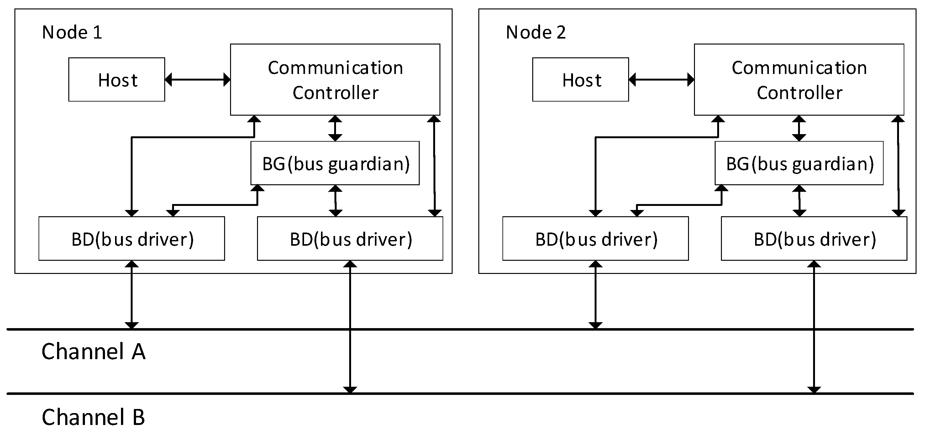
The FlexRay bus has two channels, and the maximum data rate of each channel can reach 10 Mbps, so the total data rate can reach 20 Mbps. The FlexRay node is composed of Host, Communication Controller, Bus Guardian and Bus Driver modules, as shown in
Figure 1 [
10].
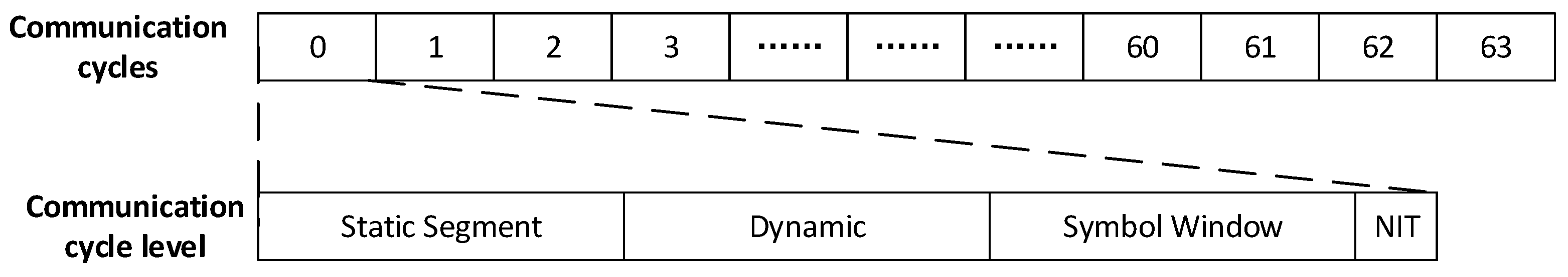
The media access control of the FlexRay bus uses both time-division multiple access and flexible time-division multiple access. A communication cycle consists of static segments, dynamic segments, symbol windows, and idle network time. Among them, the static segment is triggered by fixed time and the dynamic segment is triggered by relative time, as shown in
Figure 2 [
11].
3.1. Data Frame Format
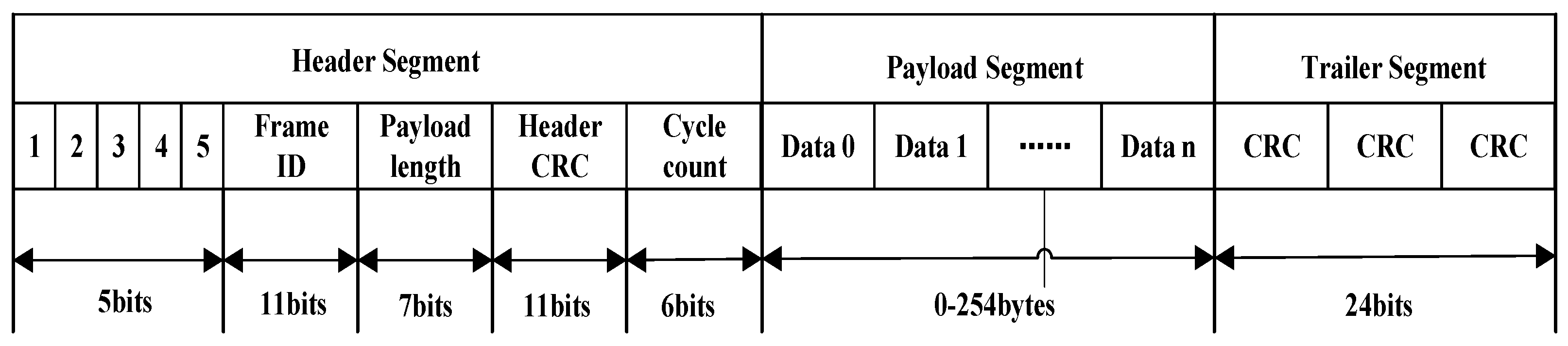
The FlexRay data frame consists of three parts: a header segment, a payload segment, and a trailer segment [
12]. When the node transmits data frames on the network, it is transmitted in the order of header segment, payload segment, and trailer segment, as shown in
Figure 3.
The first five digits of the header segment are the reserved bit, payload preamble indication bit, null frame indication bit, synchronization frame indication bit, and startup frame indication bit. The frame ID (11 digits) is the ID value of the data frame and is used to define the sending time slot of the message frame in each communication cycle. The payload length (seven digits) is the length of the payload segment. The payload segment length of the dynamic frame changes dynamically according to the length of the transmitted message. The header cyclic redundancy check (CRC) (11 digits) is the CRC check code of the header segment. The cycle count (six digits) is the communication cycle. The actual transmitted information is carried in the payload segment. The trailer segment is the CRC check code of the entire data frame.
3.2. Dynamic Segment Properties
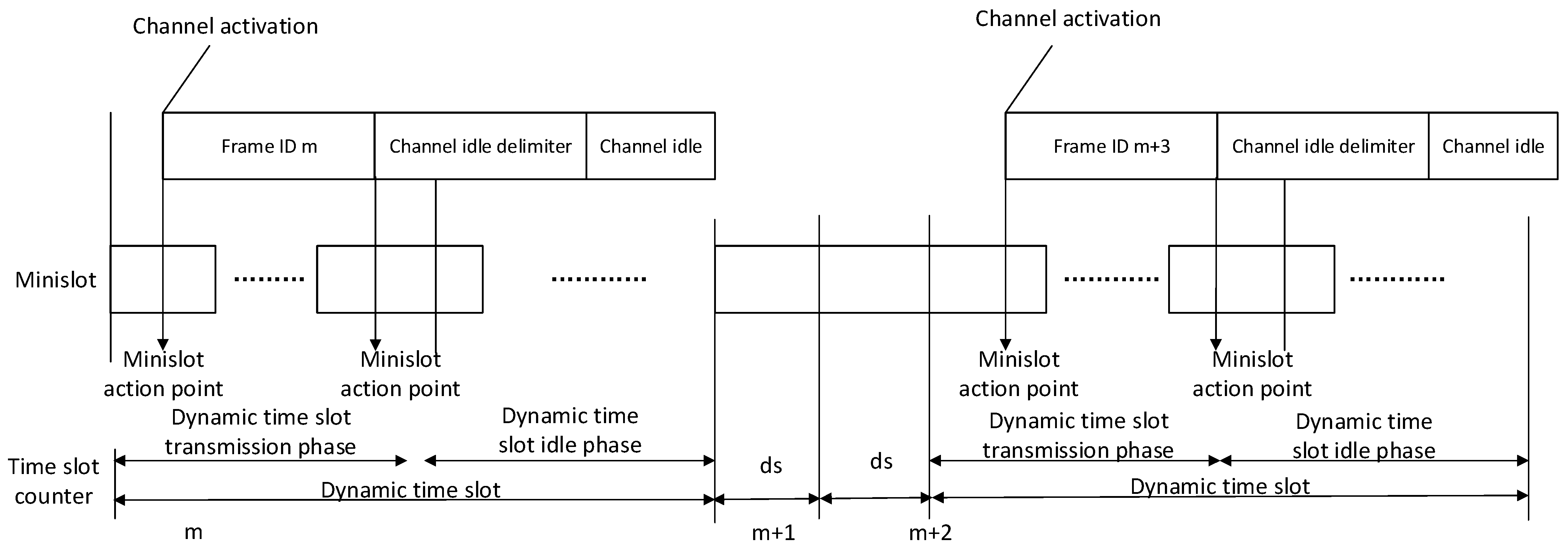
The FlexRay dynamic segments are composed of dynamic time slots, and dynamic time slots are composed of minislots. Minislots are composed of macroticks, and the dynamic time slot length varies with the length of the transmitted message. Within the dynamic segment, the access mechanism based on dynamic minimum time slots is used for arbitration transmission, mainly for non-periodic message transmission. The available bandwidth of the dynamic segment can be dynamically allocated according to actual demand. The dynamic segment contains a fixed number of minislots, which are configured during the design phase, and the maximum number of minislots is 7988. The transmission start time of a FlexRay dynamic segment message starts from the minislot trigger point and ends at the next minislot trigger point. The time interval between the minislot starting point and the minislot trigger point is called the gdMinislotActionPointOffset. The dynamic time slot consists of two parts: the dynamic time slot transmission phase and the dynamic time slot idle phase. The dynamic time slot idle phase is the waiting time for detecting an idle communication channel. The dynamic segment timing is shown in
Figure 4 [
11].
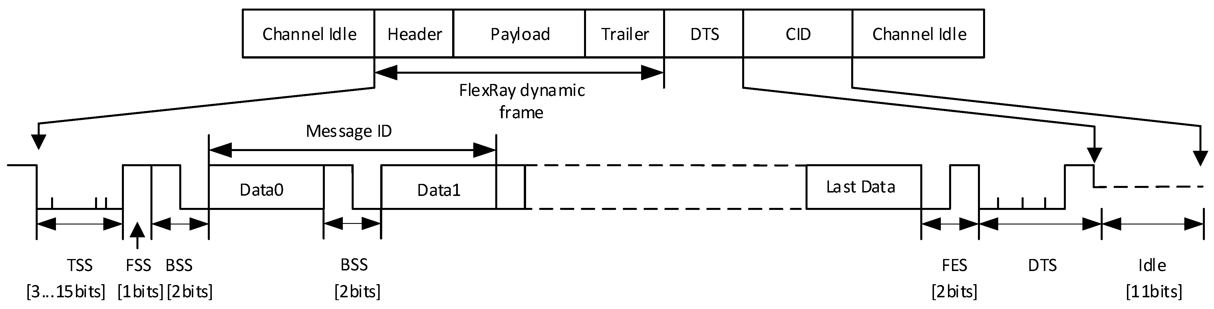
The encoding rules of the dynamic frames are shown in
Figure 5 [
11]. They are mainly composed of a transmission start sequence (TSS), frame start sequence (FSS), byte start sequence (BSS), frame end sequence (FES), and dynamic trailing sequence (DTS).
The set of messages in the dynamic segment is set to
,
is the j-th dynamic message, there are n dynamic messages, and
. When the length of message
is
bits, the encoded dynamic frame length is
, as shown in Formula (1).
In this context,
TSS represents the transmission start sequence,
FSS denotes the frame start sequence, and
FES indicates the frame end sequence. The number 80 accounts for the frame header segment, frame trailer segment, and two-byte message ID, while 1.25 includes the bits to be transmitted and the
BSS.
DTS refers to the dynamic trailing sequence, which follows the frame end sequence and has a variable length. The dynamic time slot length is detailed in Formula (2).
where
is the dynamic time slot length, and the unit is ms;
ceil is the ceiling function;
is the time to transmit each bit;
is the duration of each macrotick;
is the time required to transmit a minislot;
CDM is the maximum clock deviation;
DSIP is the dynamic time slot idle phase, which has a value range of 0–2 ms.
The length of the dynamic segment is obtained using Formula (3), where
is the number of minislots contained in the dynamic segment, and
is the length of the minislot (taken as 2 MT in this paper).
FlexRay network utilization refers to the ratio of the bandwidth actually used for message transmission to the total available bandwidth within a communication cycle. This metric is of significant importance for evaluating network performance, as it directly reflects the efficiency and resource utilization of the system during data transmission, as shown in Formula (4) [
13].
where
N (0 <
N < 63) represents the communication cycle occupied by transmitting all dynamic messages. Generally speaking, the higher the bandwidth utilization, the better the performance of the FlexRay communication system. However, if the dynamic segment is too short, the message transmission delay increases, affecting the real-time performance of the transmission. The uncertainty in the message transmission time requires further analysis of the worst response time for each message [
14].
3.3. Worst Response Time Calculation
The worst response time is the duration from message generation in the sending node to its reception in the receiving node; the unit is ms, as shown in Formula (5) [
15]:
is the delay time caused by the message exceeding the corresponding time slot of the original plan, as shown in Formula (6):
where
represents dynamic segment slot length, and
is the frame ID value of message
.
consists of the idle slot time and the message delay time, which form the delay time, as shown in Formula (7):
is the delay time caused by the failure to successfully send a high-priority message in this cycle or by an idle time slot caused by a message being sent before the preset value period. is the queuing delay time caused by messages with a higher priority than message in the priority queue of message . is the message transmission time with a higher priority than message .
The
that may occur during the transmission of dynamic segment messages within each transmission cycle can be calculated using Formula (8).
where
is the transmission time of the static segment, and
is the time before message
is sent in the dynamic segment within the sending cycle.
is the dynamic segment message transmission time. Therefore, the overall worst response time of a FlexRay dynamic segment is described by the sum of the worst response times of n messages, as shown in Formula (9):
4. Message Scheduling for Dynamic Segments
Because of the non-periodic nature of FlexRay dynamic segments, message scheduling for dynamic segments is more complex than for static segments. The message scheduling of FlexRay dynamic segments is determined based on the priority of the frame ID. Dynamic messages with small frame IDs have higher priority, and the transmission of high-priority messages may cause delays for low-priority messages. By reducing the worst response time of each message, it ensures that dynamic segment messages are transmitted before the deadline, which improves the message transmission efficiency and network utilization.
4.1. Priority Allocation of Nodes
Vehicles are equipped with various ECUs such as an engine control module (ECM), a brake control module (BCM), a chassis control module (CCM), and an infotainment system module (ISM),. Priority is given to securing important messages in real time during vehicle operation. ISO 26262 is an automotive functional safety standard issued by the International Organization for Standardization (ISO) [
16]. Its full name is Road Vehicles-Functional Safety. The standard was first published in 2011 to regulate the development, validation, and life cycle management of electronic automotive systems to ensure the safety of the vehicle during operation for passengers and other road users. Automotive Safety Integrity Level (ASIL) is a safety integrity level defined in the ISO 26262 standard and is used to evaluate the safety performance of electronic automotive systems. The ASIL is divided into four levels according to safety performance requirements: ASIL A, ASIL B, ASIL C, and ASIL D. ASIL D represents the highest safety requirements.
In this paper, the ECUs for the FlexRay bus are classified according to the ISO 26262 standard, as shown in
Table 2.
4.2. Data Frame ID Allocation
In FlexRay, the priority of a message is determined by the value of the data frame’s ID. The smaller the data frame ID value, the higher the priority. Therefore, different data frame ID allocation methods directly affect the bandwidth utilization of the dynamic segment [
17,
18].
Factors such as the length of message
, deadline
, worst response time
, and value
directly affect the priority of the message. The initial allocation of the data frame ID is based on the deadline and value of the message, and the message priority is measured by the constant
, as shown in Formula (10):
where
is the rounding function,
is the weight of the value of message
, and
is the weight of the deadline of message
.
and
are variable parameters and satisfy the constraint
, and
is the value of the message. The value indicates the priority of the ECU. The higher the priority of the ECU, the higher the message value of the message generated in the ECU.
According to the value of the message, the priority of the message can be determined, and then the best data frame ID value can be assigned. In an environment where the message value is higher and the deadline is shorter, the value is smaller, the priority is higher, and the allocated data frame’s ID value is smaller.
In this paper, data frame ID reassignment is based on the dynamic segment message length and the remaining processing time. The remaining processing time
of message
is determined by its deadline and worst response time, as shown in Formula (11):
Based on the message length and remaining processing time,
can be measured as shown in Formula (12):
where
is the rounding function, while
and
represent the weights for message length and remaining processing time, respectively, constrained by
+
= 1. The
values determine message priority: shorter
values indicate higher priority, especially in cases of longer messages and shorter processing times, leading to smaller data frame IDs. The allocation process is detailed in the pseudocode shown in Algorithm 1.
| Algorithm 1 Data frame ID allocation |
| 1: | Input: |
| 2: | Output: Allocation table for frame ID, , |
| 3: | for do |
| 4: | initialize the frame ID with and calculate |
| 5: | reassign the frame ID with and calculate |
| 6: | if > then |
| 7: | compute and allocation table for frame ID |
| 8: | else if |
| 9: | compute and allocation table for frame ID |
| 10: | end for |
To ensure the reliability of the FlexRay bus, we propose a scheduling performance analysis scheme for dynamic segment messages, where
is the period, as shown in
Figure 6, which is aimed at optimizing delivery efficiency and timeliness.
4.3. Message Compensation Scheduling
In an in-vehicle FlexRay bus network, high-priority messages are sent first, and the sending of low-priority messages is delayed [
19]. In order to further improve the transmission efficiency of low-priority messages, this paper proposes a message compensation scheduling method, as shown in
Figure 7.
By setting a deadline running time as the compensation scheduling period, the macrotick time starts after acquiring the low-priority message set . When the tick time does not reach the running time deadline, the message compensation scheduling ends. When the macrotick time reaches the deadline, the compensation time counter starts, and low-priority messages start being sent. If the compensation scheduling time is not used up, low-priority messages continue to be sent. If the compensation scheduling time is used up, the message compensation scheduling is ended.
In the process of message compensation scheduling, the compensation scheduling time affects the effect of message scheduling. When the compensation scheduling time is short, multiple compensation schedules are required for low-priority messages to be successfully sent. When the compensation scheduling time is long, it affects the real-time response to high-priority messages.
5. Analysis of Experimental Results
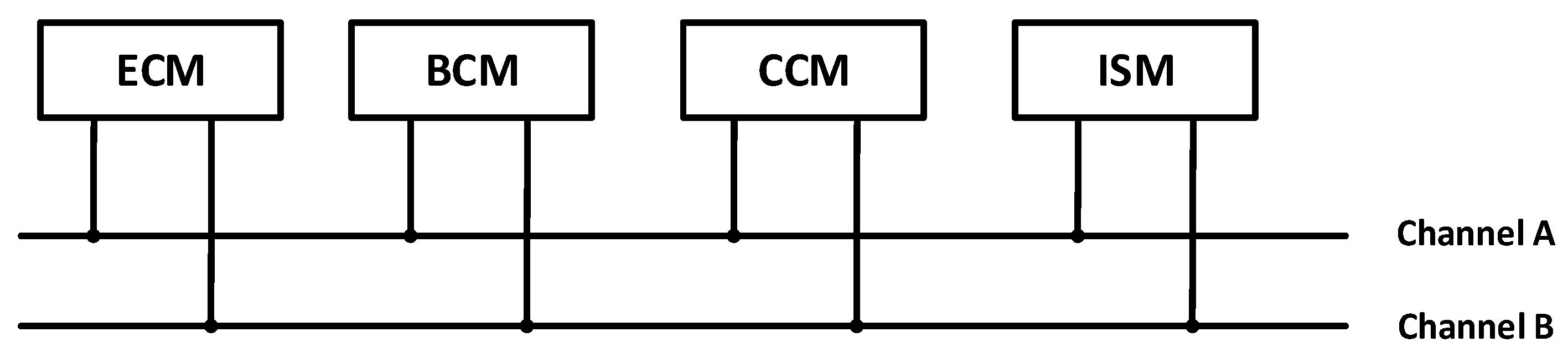
The dynamic segment message scheduling scheme proposed in this paper was validated by building an experimental platform based on the integrated control and safety system of an automotive chassis [
20].
Figure 8 is the FlexRay bus network topology, which is mainly composed of an ECM, a BCM, a CCM, and an ISM.
In this paper, the ECUs of FlexRay bus are classified according to the ISO 26262 standard. The names and specific parameters of the nodes are shown in
Table 3. There are 20 dynamic segment messages in the vehicle FlexRay bus network. The dynamic segment messages and parameters are shown in
Table 4. According to
Table 3 and
Table 4, combined with the message scheduling scheme for the dynamic segment proposed in this paper,
Table 5 presents the frame ID allocation results, with the left side of the table displaying the frame ID allocation results without using a scheduling method and the right side showing the results obtained using the proposed frame ID allocation method.
In order to evaluate the performance of the proposed method, we conducted a hardware evaluation and a software simulation.
Figure 9 shows the real environment. This paper used CANoe version 8, CANcaseXL provided the hardware license, and VN8970 was used as the Flex Ray communication interface.
In the same experimental environment, the proposed DSMSS and the EDF algorithm were simulated and compared [
21]. The bandwidth utilization of the two algorithms is compared for a bus rate of 10 Mbps in
Figure 10. When the number of messages is small, the two scheduling schemes perform similarly. As the number of messages increases, the proposed scheme shows a better ability to save network resources. This indicates that when transmitting the same number of dynamic segment messages, the DSMSS algorithm proposed in this paper utilizes less bandwidth resources, thereby enhancing the transmission efficiency of the FlexRay bus.
In
Figure 11, the worst response time of the dynamic messages under two different frame ID allocation strategies is compared. As the number of transmitted messages increases, the performance difference between the two scheduling schemes gradually becomes apparent. After all messages are transmitted, it can be clearly observed that the worst response time obtained by the DSMSS scheduling algorithm proposed in this paper is significantly shorter than that of the EDF algorithm.
Figure 12 shows the simulation results of the worst response time of low-priority messages. The x-axis represents the number of low-priority data frames transmitted, totaling 20, while the y-axis denotes the response time to low-priority messages. In this comparative experiment, a total of 44 dynamic messages were transmitted, including 20 low-priority messages. The simulation results demonstrate that the response time to low-priority messages increases with the number of low-priority messages. However, under the proposed scheduling scheme, this upward trend is significantly less pronounced compared to the EDF scheduling scheme. Specifically, when the number of low-priority messages is small, the increase in response time is relatively gradual, indicating that the proposed scheduling strategy exhibits higher efficiency in handling a limited number of low-priority messages. As the number of low-priority messages increases, although the response time rises, it remains substantially lower than that of the EDF scheduling scheme. This suggests that the proposed scheduling strategy excels in dynamically adjusting message priorities and implementing compensation mechanisms, effectively reducing the response time to low-priority messages, particularly in scenarios with a larger number of messages.
Table 6 provides the bandwidth utilization and worst-case response time of the EDF algorithm and the DSMSS algorithm for cases where the number of dynamic segment messages is 5, 10, 15, and 20. When transmitting all 20 dynamic segment messages, the DSMSS algorithm proposed in this paper improves bandwidth utilization by 28.1% and reduces the worst-case response time by 9.4% compared to the EDF algorithm. Furthermore, we calculated the 95% confidence intervals for the two algorithms. Specifically, the 95% confidence intervals for the bandwidth utilization of the DSMSS and EDF algorithms are
and
, respectively, while the 95% confidence intervals for the worst-case response time are
μs and
μs, respectively. These results clearly demonstrate that the DSMSS algorithm proposed in this paper significantly outperforms the EDF algorithm in terms of performance.
6. Conclusions
The in-vehicle FlexRay bus network is used in the chassis control systems of BMW, Mercedes-Benz, and other vehicles and has become the backbone network of next-generation in-vehicle bus networks. As automobiles become more intelligent, the number of in-vehicle ECUs continues to increase, resulting in higher real-time requirements for in-vehicle messages and a shortage of broadband resources. This paper studies the message scheduling problem of FlexRay dynamic segments. Based on a comprehensive consideration of the length, deadline, worst response time, and message value of the message, a highly efficient data frame ID allocation method and a message compensation scheduling method are proposed, which improve the transmission efficiency of low-priority messages. Additionally, this study highlights the importance of symmetry in achieving efficient and balanced communication by addressing the asymmetry in communication systems through optimized scheduling algorithms. The experimental results show that the DSMSS proposed in this paper increases the bandwidth utilization by 28.1% and reduces the worst response time by 9.4%. It lays a foundation for in-vehicle FlexRay bus networks in the development of intelligent and connected cars.


