Article

Vortex Dynamics in a Hybrid Aligned Nematic Microvolume with an Orientational Defect

by
Izabela Śliwa
1,
Pavel V. Maslennikov
2 and
Alex V. Zakharov
3,*
1
Department of Operations Research and Mathematical Economics, Poznan University of Economics and Business, Al. Niepodleglosci 10, 61-875 Poznan, Poland
2
Institute of Living Systems, Immanuel Kant Baltic Federal University, Str. Universitetskaya 2, 236040 Kaliningrad, Russia
3
Saint Petersburg Institute for Machine Sciences, The Russian Academy of Sciences, 199178 Saint Petersburg, Russia
*
Author to whom correspondence should be addressed.
Symmetry 2023, 15(2), 324; https://doi.org/10.3390/sym15020324
Submission received: 7 December 2022 / Revised: 13 January 2023 / Accepted: 18 January 2023 / Published: 23 January 2023
(This article belongs to the Section Chemistry: Symmetry/Asymmetry)

Abstract

:
The aim of this theoretical paper is to investigate the physical mechanism responsible for the appearance of vortex flow in a hybrid aligned nematic (HAN) microvolume with an orientational defect, excited by a temperature gradient T . This was done in the framework of the classical Ericksen-Leslie theory, supplemented by thermomechanical correction of the shear stress and Rayleigh dissipation function, as well as taking into account the entropy balance equation. We have carried out a numerical study of the system of hydrodynamic equations including director reorientation, fluid flow v , and the temperature redistribution across the HAN microvolume under the influence of T , when the HAN microvolume is heated from above. Calculations show that, due to the interaction between the gradient of the director field n ^ and T , the HAN microvolume settles down to a stationary complex vortex flow regime.

1. Introduction

During the last decade, detailed numerical simulations were carried out to clarify the role of the heat flux q in the formation of vortex flows in microsized channels and capillaries [1,2,3]. Special attention was paid to the role of the heat flux caused by laser radiation focused in the volume and at the boundary of the liquid crystal channel [4]. The role of conformational trans-cis and cis-trans transitions caused by focused laser radiation on the process of vortex flow v formation in microsized channels and capillaries were also investigated [5]. It is shown that a thermally excited vortex flow is maintained with motion in a positive sense (clockwise) in the vicinity of the orientation defect at the lower boundary of the hybrid aligned nematic (HAN) channel caused by the trans-cis and cis-trans conformational changes. In the case of the same HAN channel, but without the azobenzene monolayer at the lower boundary, the heat flux q can also produce the vortical flow near the laser spot at the lower boundary, directed in a negative sense (anti-clockwise), which is characterized by a much lower velocity than the vortex flow in the first case. Whatever the actual goal, the condition for initiating the vortex flow under the influence of the heat flux q caused by coupling between gradients of the director n ^ and the vertically applied temperature gradient T , in the presence of the orientation defect at the lower boundary of the HAN channel is important information for this LC system. It is necessary to understand the mechanism responsible for the excitation of the vortex flow in the microsized LC volume and the state when the excitation of this vortex flow is impossible under the effect of the vertically applied temperature gradient. Knowing this, it is possible to predict the further behavior of this LC system with the orientational defect under the effect of the temperature gradient.
Thus, our main goal is to study the role of the temperature gradient formed under the effect of focused laser radiation on the formation of the vortex flow in the microsized HAN channel. In our case, the HAN system, consisting, for example, of asymmetric molecules, such as cyanobiphenyls , confined in the microsized volume between two horizontal and two lateral surfaces under the influence of the temperature gradient T directed from the cooler lower restricted surface with the orientational defect (with the bidirectionally aligned lower surface) to the warmer upper restricted surface. This problem will be treated in the framework of the appropriate nonlinear extension of the Ericksen-Leslie theory [6,7], together with accounting the thermoconductivity equation for the temperature field T [8].
The layout of this article is as follows. In the next section, we will give the theoretical background for describing the physical mechanism responsible for the heat-induced vortex flow in the HAN microvolume with the bidirectionally aligned lower surface. The numerical description of the occurrence of the vortex flow in the HAN microvolume under the effect of the temperature gradient directed from the cooler lower to the warmer upper restricted surfaces is given in Section 3. Our conclusions are given in Section 4.

2. Basic Hydrodynamic Equations

To investigate the heat-driven microfluidics of a liquid crystal system confined to a hybrid aligned volume with an orientational defect, we consider the LC drop delimited by two horizontal and two lateral surfaces at mutual distances d and 2 L on scale on the order of micrometers, with the warmer upper restricted surface
T L < x < L , z = d = T up ,
whereas in the rest of the boundaries, the temperature
T L x L , z = 0 = T x = L , 0 < z < d = T x = L , 0 < z < d = T lw ,
is kept lower ( T up > T lw ). Thus, we will investigate the role of a temperature gradient T in exciting of the vortex flow v = v x i ^ + v z k ^ = u i ^ + w k ^ in the hybrid aligned nematic (HAN) drop. In our case, the coordinate system assumed that the director n ^ = n x i ^ + n z k ^ = sin φ i ^ + cos φ k ^ is in the X Z plane, where φ is the polar angle between the director n ^ and the normal vector k ^ to the horizontal surfaces, while i ^ is the unit vector directed parallel to the upper and lower restricted surfaces, and j ^ = k ^ × i ^ .
Thus, we are dealing with the HAN microvolume, where the director’s orientation on the upper ( n ^ z = d k ^ ) (homeotropic anchoring) and on the side ( k ^ n ^ x = ± L ) (homogeneous anchoring) restricted surface is parallel to the unit vector k ^ , while on the lower restricted surface the director n ^ is tilted with respect to the normal vector k ^ . Consequently, in our case, the nematic volume contains a complex gradient φ due to the bidirectional orientation on the lower surface with a transition to the homogeneous orientation on both side surfaces, as well as with a further transition to the homeotropic orientation on the upper surface, respectively, i.e.,
φ 0 x < L , z = 0 = π 4 , φ L < x < 0 , z = 0 = π 4 , φ L < x < L , z = d = 0 , φ x = L , 0 < z < d = 0 , φ x = L , 0 < z < d = 0 .
Thus, a complex gradient of the director field n ^ is formed in the HAN drop, which will interact with the temperature gradient T formed across the HAN volume, due to the temperature difference Δ T = T up T lw on the upper ( T up ) and lower ( T lw ) bounding surfaces.
Moreover, we will assume the no-slip boundary conditions for the nematogenic molecules on these bounding surfaces, i.e.,
v L < x < L , z = 0 , d = v x = ± L , 0 < z < d = 0 .
Taking into account the fact that the mass density ρ is constant in the microsized HAN volume, we can assume that we can deal with an incompressible liquid · v = 0 . In our case, the incompressibility condition assumes that
u , x + w , z = 0 ,
where u v x ( x , z , t ) and w v z ( x , z , t ) are the components of the vector v = u i ^ + w k ^ , and u , x = u x .
The hydrodynamic equations describing the reorientation of the LC phase in the 2D case, when there exists a heat flux q across the HAN microvolume, can be derived from the torque balance equation Γ el + Γ vis + Γ tm = 0 , where Γ el = δ Ψ el δ n ^ × n ^ is the elastic [2,5], Γ vis = δ R vis δ n ^ t × n ^ t is the viscous [2,5], and Γ tm = δ R tm δ n ^ t × n ^ is the thermomechanical [9] torques, respectively. In turn, the linear momentum balance equation for the velocity field v has the form [2,5]
ρ d v d t = · Σ ,
where Σ = Σ el + Σ vis + Σ tm P E is the full stress tensor (ST), and Σ el = Ψ el n ^ · n ^ T , Σ vis = δ R vis δ v , and Σ tm = δ R tm δ v are the ST components corresponding to the elastic, viscous, and thermomechanical forces [2,5], respectively. Here R = R vis + R tm + R th is the full Rayleigh dissipation function, Ψ el = 1 2 K 1 · n ^ 2 + K 3 n ^ × × n ^ 2 is the elastic energy density, while P is the hydrostatic pressure in the HAN system. A number of constants K 1 and K 3 denotes the splay and bend elastic coefficients, while E is the unit tensor. In our case the entropy balance equation the form [8]
ρ C P d T d t = · q ,
where q = T δ R δ T is the heat flux in the HAN system, T ( z , t ) is the temperature field that is formed across the HAN channel, and C P is the heat capacity of the LC system.
In order to investigate the evolution of the angle φ ( x , z , t ) to its stationary orientation φ st ( x , z ) , the process of excitation of the vortex flow v ( x , z , t ) caused by the interaction of temperature and the director gradients, as well as the redistribution of the temperature field T ( x , z , t ) to its stationary distribution T st ( x , z ) over the HAN microvolume, we consider a dimensionless analog of these equations. The dimensionless torque balance equation has the form [2,5]
θ , τ = 1 2 1 + γ cos 2 φ Ω , zz 1 2 1 γ cos 2 φ Ω , xx + γ sin 2 φ Ω , xz + sin 2 φ + K 31 cos 2 φ φ , xx + cos 2 φ + K 31 sin 2 φ φ , zz + K 31 1 φ , xz + 1 2 φ , z 2 φ , x 2 sin 2 φ + φ , x φ , z cos 2 φ 1 2 δ 1 χ , z sin 2 φ φ , x + 2 φ , z + cos 2 φ φ , z Ω , z φ , x + Ω , x φ , z ,
where Ω = γ 1 K 1 ω is the scaled analog of the current function ω for the velocity field v = u i ^ + w k ^ = × j ^ ω , K 31 = K 3 K 1 , and γ = γ 2 γ 1 are the elastic and viscous constants of the LC system. The dimensionless analog of the Navier–Stokes equation takes the form [2,5]
δ 2 u , τ = Σ xx , x vis + Σ zx , z vis + Σ xx , x el + Σ zx , z el + δ 1 Σ xx , x tm + Σ zx , z tm P , x δ 2 u u , x ,
δ 3 w , τ = Σ xz , x vis + Σ zz , z vis + Σ xz , x el + Σ zz , z el + δ 1 Σ xz , x tm + Σ zz , z tm P , z δ 3 w w , z ,
were the set of functions Σ ij vis ( i , j = x , z ) , Σ ij el ( i , j = x , z ) and Σ ij tm ( i , j = x , z ) are given in the Refs. [2,5], whereas the dimensionless entropy balance equation takes the form [2,5]
δ 4 χ , τ = λ sin 2 φ + cos 2 φ χ , zz + λ 1 sin 2 φ φ , z χ , z + δ 4 Ω , x χ , z ,
where λ = λ / λ , χ χ ( z , τ ) = T ( z , τ ) / T NI is the dimensionless temperature, τ = K 1 γ 1 d 2 t is the dimensionless time, z ¯ = z d is the dimensionless distance away from the bottom of the LC drop, corresponding to z-axis, x ¯ = x d is the dimensionless space variable corresponding to x-axis, δ 1 = ξ T NI K 1 , δ 2 = ρ L K 1 d γ 1 2 , δ 3 = ρ K 1 γ 1 2 , and δ 4 = ρ C p K 1 γ 1 λ are parameters of the LC system. Here 2 L is the length, whereas d ( d = L ) is the thickness of the 2 D LC film.
It should be taken into account that the overbars in the space variables x and z have been (and will be) eliminated in the last as well as in the following equations.
Now the process of reorientation of the director in a microsized HAN volume, accounting for the backflow, is governed by viscous, elastic and thermomechanical forces. In that case, the relaxation regime the director φ ( x , z , τ ) , velocity v ( x , z , τ ) and temperature χ ( z , τ ) fields can be obtained by solving the system of nonlinear partial differential Equations (8)–(11) with the appropriate dimensionless boundary conditions for the angle
φ 0 x 1.0 , z = 0 = π 4 , φ 1.0 < x < 0 , z = 0 = π 4 , φ 1.0 < x < 1.0 , z = 1 = 0 , φ x = 1.0 , 0 < z < 1 = 0 , φ x = 1.0 , 0 < z < 1 = 0 ,
velocity
v 1.0 < x < 1.0 , z = 0 , 1 = v x = ± 1.0 , 0 < z < 1 = 0 ,
and temperature
χ 1.0 < x < 1.0 , z = 1 = χ up , χ 1.0 x 1.0 , z = 0 = χ x = 1.0 , 0 < z < 1 = χ x = 1.0 , 0 < z < 1 = χ lw .
Here χ up = T up / T NI and χ lw = T lw / T NI are the dimensionless temperatures corresponding to the highest and lowest values, respectively. Thus, when the director n ^ is strongly bidirectionally anchored to the lower restricted surface, homeotropically to the upper and planar to two lateral restricted surfaces, the angle φ has to satisfy the boundary conditions (12) and its initial orientation is chosen equal to φ ( x , z , τ = 0 ) = φ el in ( x , z ) . Notice that the initial distribution of the angle φ el in ( x , z ) is obtained from Equation (8), with Ω , x = Ω , z = χ , z = 0 , and the boundary conditions in the form of Equation (12), whereas the initial condition for the polar angle φ el in ( x , z , τ = 0 ) is chose equal to 0.

3. Numerical Results for the Microsized Hybrid Aligned Nematic System

Numerical investigations will be carried out for a sample of 4 n p e n t y l 4 c y a n o b i p h e n y l (5CB) confined between two horizontal and two lateral surfaces at a distance of d = 5 μ m, at the temperature 300 K and density 10 3   kg / m 3 . The measured values of the elastic constants are chosen equal to K 1 = 10.5   pN and K 3 = 13.8   pN [10], while the experimental values both for the rotational and six Leslie coefficients are (in [ Pa s ] [11]) γ 1 0.072 , γ 2 0.079 , α 1 0.0066 , α 2 0.075 , α 3 0.0035 , α 4 0.072 , α 5 0.048 , and α 6 0.03 , respectively. The measured value of the heat conductivity coefficients parallel ( λ ) and perpendicular ( λ ) to the director are (in [ W / mK ] [12]) 0.24 and 0.13, respectively. In the following, we use the measured value of the specific heat [13] C p 10 3 [ J / kgK ] . The set of parameters that is involved in Equations (8)–(11) has the following values: δ 1 ∼29, δ 2 2 × 10 5 , δ 3 2 × 10 6 , and δ 4 1.1 × 10 3 . Using the fact that δ i 1 ( i = 2 , 3 ) , the Navier–Stokes equations [Equations (9) and (10)] can be considerably simplified and take the form
c 1 Ω , zzzz + c 2 Ω , xzzz + c 3 Ω , xxzz + c 4 Ω , xxxz + c 5 Ω , xxxx + c 6 Ω , zzz + c 7 Ω , xzz + c 8 Ω , xxz + c 9 Ω , xxx + c 10 Ω , zz + c 11 Ω , xz + c 12 Ω , zz + F = 0 ,
where c i φ ( i = 1 , , 12 ) and F φ , χ are functions which have been defined in Refs. [1,5]. Equation (11) also can be simplified because the parameter δ 4 1 , and the whole left-hand side of Equation (11), as well as the last term, can be neglected so that Equation (11) become
λ sin 2 φ + cos 2 φ χ , zz + λ 1 sin 2 φ φ , z χ , z = 0 .
Thus, the response of the HAN microvolume with the orientational defect in the above setting is described by Equations (8), (15) and (16), together with the boundary conditions Equations (12)–(14), and the initial condition
φ ( x , z , τ = 0 ) = φ el x , z ,
where φ el x , z is the stationary distribution of the angle φ across the HAN drop under the influence of the elastic force.
First of all, let’s study how the coupling of the director and temperature gradients affects the evolution of the director n ^ ( x , z , τ ) [or polar angle φ ( x , z , τ ) ] to its stationary distribution n ^ st ( x , z , τ = τ R ) , both near the bidirectional defect and in the volume of the HAN microvolume. This was achieved by solving the system of the nonlinear partial differential Equations (8), (15) and (16), together with the boundary (Equations (12)–(14)) and the initial (Equation (17)) conditions by means of the sweep method [14]. In this case, the initial distribution of the angle φ e l i n ( x , z ) was obtained from Equation (8) using the relaxation method [15], with u , x = u , z = w , x = w , z = χ , z = 0 and with boundary conditions in the form of Equations (12) and (14), whereas the initial condition for the polar angle φ is chosen as φ e l ( x , z , τ = 0 ) = 0 . In our case, the magnitude and direction of the hydrodynamic flow is affected by both the gradient of the director field n ^ (or φ ) and the temperature gradient χ . Notice that the largest value n ^ (or φ ) is reached near the orientation defect, where the director’s orientation characterized by sharp changing along the lower bounding surface, from one tilted ( φ 1.0 < x < 0 , z = 0 = π 4 ) to another tilted ( φ 0 < x < 1.0 , z = 0 = π 4 ) orientation. Using the fact that | n ^ | (or | φ | ) | χ | and | v | , the nonlinear system of the partial differential Equations (8), (15) and (16) can be simplified to the system of two linear Equations (15) and (16), with the coefficients of these equations c i ( i = 1 , , 12 ) and F , depending on φ el ( x , z , τ ) . Later we replaced the set functions c i ( φ ( x , z , τ ) ) ( i = 1 , , 12 ) and F φ ( x , z , τ ) , χ x , z , τ by functions c i φ el ( x , z , τ ) ( i = 1 , , 12 ) and F φ el ( x , z , τ ) , χ x , z , τ . Now, Equation (15) contains unknown functions c i φ el ( x , z ) ( i = 1 , , 12 ) , which can be obtained from Equation (8), for instance, by solving the relaxation method [15], together with the boundary and initial conditions in the form of Equation (12). In turn, the functions F φ el ( x , z , τ ) , χ x , z , τ can be obtained from the Equation (16), by means of the alternating directions method [14], with u = Ω , z and w = Ω , x . In this case, the necessary boundary and initial conditions are taken in the form of Equations (14) and (17). The next time step τ = Δ τ for the velocity field is determined by the five-point sweep method [11]. In the notation of the stream function, the no-slip boundary conditions are Ω ( x , z Γ ) = Ω , x ( x , z Γ ) = Ω , z ( x , z Γ ) = 0 , where Γ is the boundary of the LC volume. The stability of the numerical procedure for Equation (15) is defined by the condition
min 1.0 x 1.0 , 0 z 1 c 5 φ el ( x , z , τ ) c 1 φ el ( x , z , τ ) Δ z Δ x 4 2 3 ,
while the stability condition of the numerical procedure for Equation (16) is defined by
2 Δ τ D 1 φ el ( x , z , τ ) Δ x 2 + D 2 φ el ( x , z , τ ) Δ z 2 ,
where D 1 φ el ( x , z , τ ) = λ sin 2 φ el ( x , z , τ ) + cos 2 φ el ( x , z , τ ) , D 2 φ el ( x , z , τ ) = λ cos 2 φ el ( x , z , τ ) + sin 2 φ el ( x , z , τ ) , Δ τ is the time step, whereas Δ x and Δ z are the space steps in the x and z directions, respectively. In the calculations, the relaxation criterion
ϵ = | ( φ ( m + 1 ) ( x , z , τ ) φ ( m ) ( x , z , τ ) ) φ ( m ) ( x , z , τ ) |
was chosen to be equal to 10 4 , and the numerical procedure was then carried out until a prescribed accuracy was achieved. Here m is the iteration number and τ R is the relaxation time of the system.
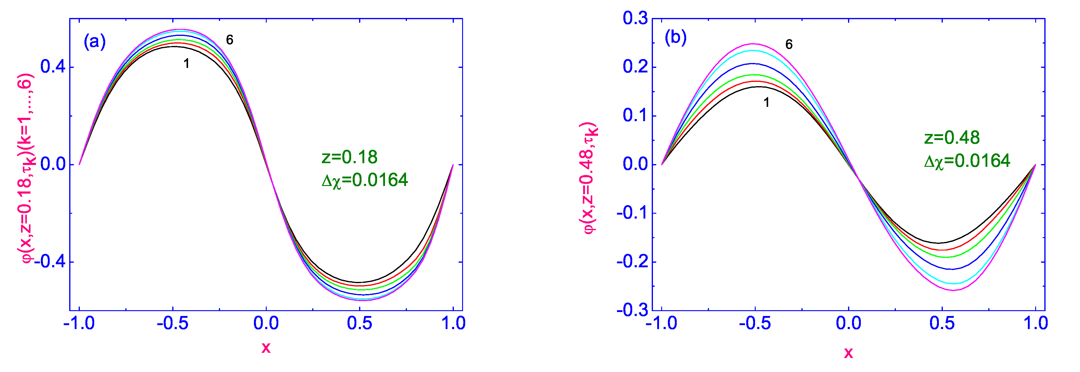
Plots of the polar angle φ x , z i , τ k ( k = 1 , , 6 ) to its stationary distribution φ s t x , z i , τ R = τ 6 along the width 1.0 x 1.0 of the HAN microvolume, for two values of dimensionless distance z 1 = 0.18 (Figure 1a) and z 2 = 0.48 (Figure 1b), calculated from the orientation defect on the lower surface, where the director’s orientation is characterized by sharp changing along the lower bounding surface, from one tilted ( φ 1.0 < x < 0 , z = 0 = π 4 ) to another tilted ( φ 0 < x < 1.0 , z = 0 = π 4 ) orientation, are shown in Figure 1a,b, respectively.
Here the dimensionless temperature difference is equal to Δ χ = χ up χ lw = 0.0162 (∼ 5 K ) , while the first 6 time slots are as follows: the first, after switching on the dimensionless temperature difference Δ χ = 0.0162 ( 5 K ) , corresponds to the time τ 1 = 0.001 (∼ 171 μ s ) , the second, corresponds to the time τ 2 = 0.005 ( 0.86 ms ) , while the other 4 correspond to the times τ i + 2 = Δ τ i ( i = 1 , , 4 ) , where Δ τ = 0.02 . Calculations show that the reorientation of the director field near the orientational defect is characterized by a sharp change in the magnitude of the polar angle φ ( x , z i , τ k ) ( k = 1 , , 6 ) along the width 1.0 x 1.0 of the HAN microvolume. Indeed, the maximal oscillation of the magnitude of the polar angle Δ φ = φ max x , z i , τ k φ min x , z i , τ k ( k = 1 , , 6 ) , for the value of dimensionless distance z 1 = 0.18 , is equal to 1.112, while for the value z 2 = 0.48 , is equal to 0.496, which is practically in two times less.
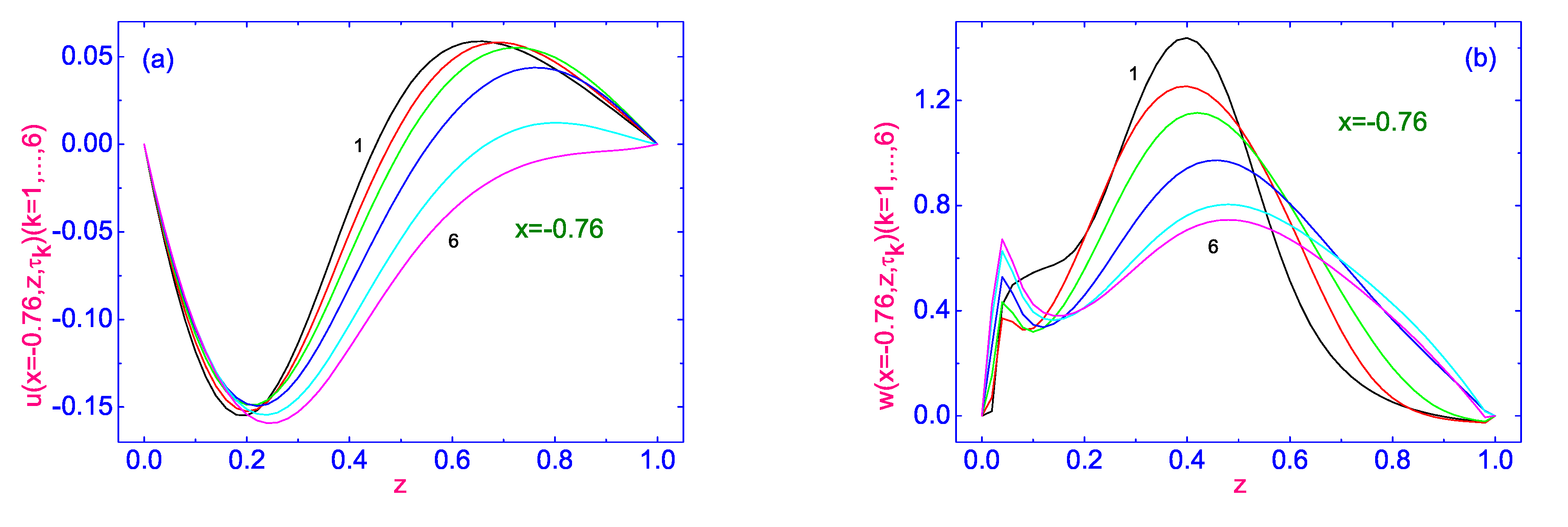
The evolution of both horizontal u x , z = 0.18 , τ k ( k = 1 , , 6 ) (see Figure 2a) and vertical w x , z = 0.18 , τ k ( k = 1 , , 6 ) (see Figure 2b) components of the velocity field to their stationary distributions u s t x , z = 0.18 and w s t x , z = 0.18 , along the width 1.0 x 1.0 of the HAN microvolume and far from the orientational defect ( z = 0.18 ), are shown in Figure 2.
The stationary distribution of the horizontal component u x , z = 0.18 , τ 6 of the velocity field is characterized by a multidirectional flow. Indeed, near the left ( 1.0 x 0.86 ) and right ( 0.32 x 1.0 ) vertical bounding surfaces, the flow is directed in a positive sense, while in the central region ( 0.86 < x < 0.32 ) it is directed in a negative sense. Moreover, near the right vertical boundary, the value of the horizontal component of the velocity field u x = 0.8 , z = 0.18 , τ 6 0.6 ( 20 μ m/s) is about an order of magnitude greater than the value of this velocity near the left vertical boundary u x = 0.92 , z = 0.18 , τ 6 0.03 ( 1 μ m/s). In the central region ( 0.86 < x < 0.32 ), the greatest value of the horizontal component u x = 0.62 , z = 0.18 , τ 6 is ∼ 0.16 ( 5.3 μ m/s), and the flow of the nematic material is directed in a negative sense. In turn, the stationary distribution of the vertical component w x , z = 0.18 , τ 6 of the velocity field is characterized by a flow in a positive sense, and the greatest value of the vertical component of the velocity field w x = 0.76 , z = 0.18 , τ 6 is ∼ 1.6 ( 53 μ m/s).
The evolution of the vertical w x , z = 0.04 , τ k ( k = 1 , , 6 ) component of the velocity field to its stationary distribution w s t x , z = 0.04 , along the width 1.0 x 1.0 of the HAN microvolume, near the orientational defect z = 0.04 is shown in Figure 3a, while Figure 3b illustrates the evolution of the same component of the velocity field w x = 0.76 , z , τ k ( k = 1 , , 6 ) to its stationary distributions across the HAN microvolume, near the left bounding surface x = 0.76 .
In the vicinity of the orientational defect, the vertical component of the velocity field is mainly directed in the positive sense, excluding a small area near the left vertical boundary ( 0.94 < x < 0.63 ) of the LC microvolume, where the flow of nematic material is directed in the negative sense. Here, the greatest value of w x = 0.8 , z = 0.04 , τ 6 is ∼ 0.3 ( 10 μ m/s), while in the rest part of the microvolume the greatest value of w x = 0.09 , z = 0.04 , τ 6 is ∼ 4.5 ( 150 μ m/s). At the same time, the evolution of the vertical w x = 0.76 , z , τ component of velocity field to its stationary distribution, across the thickness 0 z 1.0 of the dimensionless LC drop, near the left bounding surface x = 0.76 , is characterized by the flow in a positive sense, where the greatest value of w x = 0.76 , z = 0.49 , τ 6 is ∼ 0.75 ( 25 μ m/s).
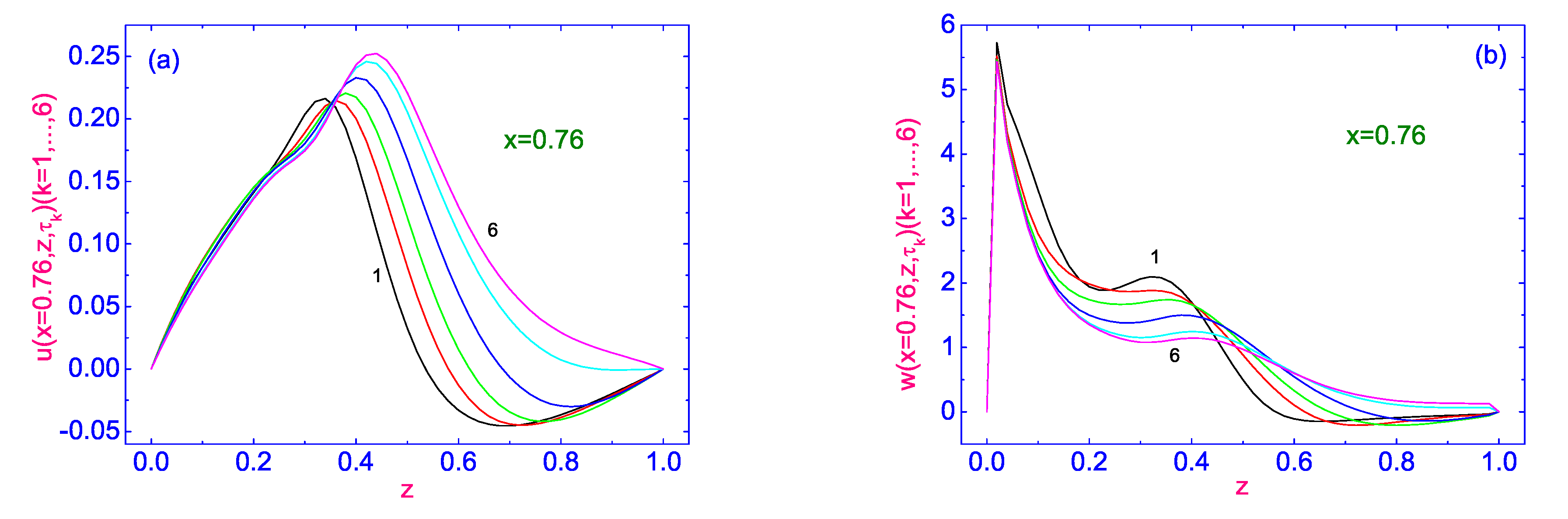
As we approach the center of the HAN microvolume, the distribution of both the horizontal u x , z = 0.48 , τ k ( k = 1 , , 6 ) (Figure 4a) and vertical w x , z = 0.48 , τ k ( k = 1 , , 6 ) (Figure 4b) components of the velocity field to their stationary distributions u s t x , z = 0.48 and w s t x , z = 0.48 , along the width 1.0 x 1.0 of the HAN microvolume, changes.
The evolution of horizontal u x , z = 0.48 , τ k ( k = 1 , , 6 ) (see Figure 4a) component of the velocity field to its stationary distribution u s t x , z = 0.48 along the width 1.0 x 1.0 of the LC drop, calculated far ( z = 0.48 ) from the orientational defect is characterized by a multidirectional flow. Indeed, near the left ( 1.0 x 0.77 ) and right ( 0.17 x 1.0 ) vertical bounding surfaces, the flow is directed in a positive sense, while in the central region ( 0.77 < x < 0.17 ) it is directed in a negative sense. Moreover, near the right vertical boundary, the value of the horizontal component of the velocity field u x = 0.56 , z = 0.48 , τ 6 0.24 ( 8 μ m/s) is about three times greater than the value of this velocity in the domain with the flow u x = 0.39 , z = 0.48 , τ 6 0.1 ( 3.3 μ m/s) directed in the negative sense. At the same time, the evolution of the vertical w x , z = 0.48 , τ k ( k = 1 , , 6 ) component of velocity field to its stationary distribution, along the width 1.0 x 1.0 of the LC drop calculated far ( z = 0.48 ) from the orientational defect is characterized by the flow in the positive sense, and the greatest value of w x = 0.4 , z = 0.48 , τ 6 is ∼ 1.15 ( 38.3 μ m/s).
The evolution of the velocity field v x , z , τ k = u x , z , τ k i ^ + w x , z , τ k k ^ ( k = 1 , , 6 ) to its stationary distribution across the HAN microvolume 0 z 1.0 , near the left ( x = 0.76 ) and right ( x = 0.76 ) vertical bounding surfaces are shown in Figure 5 and Figure 6, respectively.
The evolution of the horizontal u x = 0.76 , z , τ k ( k = 1 , , 6 ) (see Figure 5a) component of the velocity field to its stationary distribution u s t x = 0.76 , z across the HAN microvolume 0 z 1.0 is characterized by a multidirectional flow. Indeed, during the first 5 time terms, starting from τ 1 = 0.001 ( 171 μ s ) to τ 5 = 0.06 ( 10.3 ms ) , the flow near the orientational defect is directed in the negative sense, while the rest of the LC material is moving in the positive sense. At the same time, the area adjacent to the lower bounding surface of the LC droplet expanded all the time, and finally, the stationary flow of LC material is directed in the negative sense after time term τ 6 = τ R = 0.08 ( 13.7 ms ) . It should be noted that the evolution of the vertical w x = 0.76 , z , τ k ( k = 1 , , 6 ) (see Figure 5b) component of velocity field to its stationary distribution across the HAN microvolume 0 z 1.0 is characterized by the flow directed in the positive sense, and the greatest value of w x = 0.76 , z = 0.48 , τ 6 is ∼0.72 (∼24 μ m/s). The evolution of the velocity field v x = 0.76 , z , τ k = u x = 0.76 , z , τ k i ^ + w x = 0.76 , z , τ k k ^ ( k = 1 , , 6 ) to its stationary distribution across the HAN microvolume 0 z 1.0 , near the right vertical bounding surface ( x = 0.76 ) is also characterized by a multidirectional flow. During the first 5 time terms started from τ 1 = 0.001 ( 171 μ s ) to τ 5 = 0.06 ( 10.3 ms ) , the flow near the lower bounding surface z = 0.0 of the microsized LC volume is directed in the positive sense, while the rest volume of the LC material is moving in the negative sense. At the same time, the area adjacent to the orientational defect in the LC droplet expanded all the time, and finally, the stationary flow of LC material is directed in the positive sense after time term τ 6 = τ R = 0.08 ( 13.7 ms ) . It should be noted that the evolution of the vertical w x = 0.76 , z , τ k ( k = 1 , , 6 ) (see Figure 6b) component of velocity field to its stationary distribution across the HAN microvolume 0 z 1.0 near the right bounding surface is characterized by the flow directed in the positive sense, and the greatest value of w x = 0.76 , z = 0.002 , τ 6 is 5.75 ( 192 μ m/s).
In order to give a complete picture of the origin of vortex flows in the microsized HAN volume under the effect of the vertically directed temperature gradient χ , we calculate the evolution of r o t v = × v . The distribution of the velocity field v in the HAN microvolume for the number of times, τ 1 = 0.001 ( 171 μ s ) , τ 5 = 0.06 ( 10.3 ms ) , and τ 6 = τ R = 0.08 ( 13.7 ms ) , after setting up of the temperature gradient χ , are shown in Figure 7, Figure 8 and Figure 9, respectively.
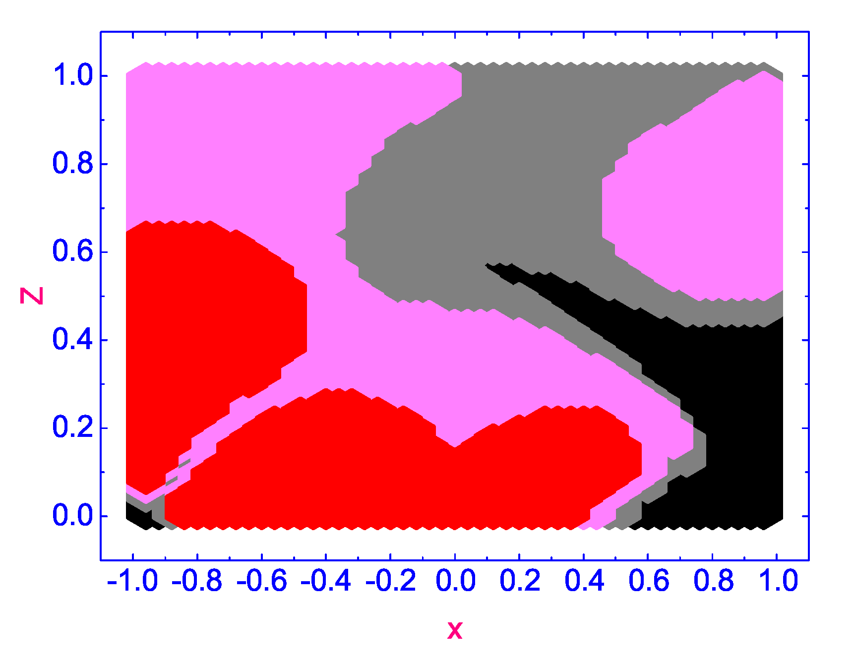
According to our calculations, a number of complex vortex domains rotating in opposite directions are excited in the HAN microvolume under the effect of the temperature gradient χ : two domains with the vortex flow excited in the negative sense around their centers with × v < 0 (rotating anti-clockwise) (pink colored domains), one domain with the vortex flow excited in the positive sense around its center with × v > 0 (rotating clockwise) (gray colored domain), and two domains, both with a small × v ± 0 (slowly rotating clockwise) (red colored domain) and (slowly rotating anti-clockwise) (black colored domain), respectively. Over time τ 5 = 0.06 ( 10.3 ms ) (see Figure 8), the complex pattern of forming vortices in the microscopic HAN volume changes, and domains with small values of × v ± 0 are displaced to the boundaries of the HAN cell, while three domains with × v > 0 (rotating clockwise) (gray colored domains) and one with × v < 0 (rotating anti-clockwise) (pink colored domain) are moved to the central part of the HAN volume. As the HAN microvolume warms up further, up to τ 6 = τ R = 0.08 ( 13.7 ms ) (see Figure 9), the picture of the distribution of rotating domains is finally formed. Three domains with × v > 0 (rotating clockwise) (gray-colored domains) are formed near the upper and lower corners and to the right of the center of the HAN microvolume, while one domain with × v < 0 (rotating anti-clockwise) (pink-colored domain) is placed to the left of the center of the HAN cell. At the same time, two domains with small values of × v ± 0 (slowly rotating clockwise) (red-colored domain) and (slowly rotating anti-clockwise) (black-colored domain), where rotation is almost negligible, are shifted closer to the boundaries of the HAN cell.
Thus, in the quasi-two-dimensional HAN microvolume with the complex surface alignment of the director field along the perimeter of the LC cell, the complex pattern of vortex flows is formed under the effect of the temperature gradient after the time τ 6 = τ R = 0.08 ( 13.7 ms ) , as shown in Figure 9.

4. Conclusions

In summary, we have investigated the complex vortex dynamics in thin hybrid aligned nematic (HAN) cell with the orientational defect on the lower restricted surface of this LC cell. It was shown that when the nematic sample confined by two horizontal and two lateral surfaces is heated from above, a number of complex vortex domains rotating in opposite directions are formed inside this microvolume under the effect of the temperature gradient T . Our calculations based on the corresponding nonlinear extension of the classical Ericksen-Leslie theory show that due to the interaction between T and the gradient of the director field n ^ , the self-sustaining thermally excited complex vortex fluid flow is maintained in the HAN microvolume. The direction and magnitude of hydrodynamic flow are influenced by both the direction of the heat flux and the nature of the orientational defect on the bounding surfaces.
A possible experiment to detect a vortex flow in a microsized hybrid aligned nematic droplet consisting, for example, of 5CB molecules can be carried out as follows. Consider a nematic drop confined in a microsized cell with the director’s orientation on the upper and on both sides of the bounded surfaces, as described in Section 2. Let us consider the orientational defect on the lower bounding surface, where the director’s orientation is characterized by sharp changing along the bounding surface, from one tilted ( φ 1.0 < x < 0 , z = 0 = π 4 ) to another tilted ( φ 0 < x < 1.0 , z = 0 = π 4 ) orientation. Immerse the LC cell in liquid at temperature T lw , while the upper surface will remain at room temperature T up , so that T up > T lw . Thus, it will be possible to form a temperature gradient T across the LC cell. If initially the marker particles are stirred in the isotropic volume of the LC material, then this system is cooled to the nematic state of the LC material, thus a hydrodynamic flow will form in the LC system as a result of the interaction of temperature T and director n ^ gradients. Marker particles allow us to observe vortex flows formed in microsized HAN volumes under the influence of the temperature gradient. This vortex flow will persist for the entire period of time when the above-described state of the LC system is maintained.
We believe that the present investigation can shed some light on the problem of control of the dynamic response of the bidirectionally aligned LC display under the influence of the temperature gradient.

Author Contributions

I.Ś. and P.V.M.: writing—original draft preparation and editing. A.V.Z.: writing—original draft preparation and editing; supervision. All authors have read and agreed to the published version of the manuscript.

Funding

The reported study was funded by the Russian Science Foundation, project number 23-12-00086.

Data Availability Statement

Not applicable.

Conflicts of Interest

The authors declare no conflict of interest.

References

  1. Zakharov, A.V.; Vakulenko, A.A. Thermally excited vortical flow in a microsized nematic cell. RCS Adv. 2012, 2, 7296–7304. [Google Scholar] [CrossRef]
  2. Zakharov, A.V.; Vakulenko, A.A. Temperature-driven motion of liquid crystals confined in a microvolume. Phys. Fluids 2013, 25, 113101. [Google Scholar] [CrossRef]
  3. Śliwa, I.; Zakharov, A.V. Heat driven flow in microsized nematic volumes: Computational studies and analysis. Symmetry 2021, 13, 459. [Google Scholar] [CrossRef]
  4. Zakharov, A.V.; Maslennikov, P.V. Nature of thermally excited vortical flow in a microsized nematic volume. Phys. Rev. E 2019, 99, 032701. [Google Scholar] [CrossRef] [PubMed]
  5. Sliwa, I.; Maslennikov, P.V.; Zakharov, A.V. Microfluidics of liquid crystals induced by laser radiation. Phys. Rev. E 2021, 103, 062702. [Google Scholar] [CrossRef] [PubMed]
  6. Ericksen, J.L. Anisotropic Fluids. Arch. Ration. Mech. Anal. 1960, 4, 231–237. [Google Scholar] [CrossRef]
  7. Leslie, F.M. Some constitutive equations for liquid crystals. Arch. Ration. Mech. Anal. 1968, 28, 265–283. [Google Scholar] [CrossRef]
  8. Landau, L.D.; Lifshitz, E.M. Fluid Mechanics; Pergamon Press: Oxford, UK, 1987. [Google Scholar]
  9. Akopyan, R.S.; Zeldovich, B.Y. Thermomechanical effects in deformed nematics. Sov. Phys. JETP 1984, 87, 1660–1669. [Google Scholar]
  10. Madhusudana, N.V.; Pratibha, R.P. Elasticity and orientational order in some cyanobiphenyls: Part IV. Reanalysis of the data. Mol. Cryst. Liq. Cryst. 1982, 89, 249–257. [Google Scholar] [CrossRef]
  11. Chmielewski, A.G. Viscosity coefficients of some nematic liquid crystals. Mol. Cryst. Liq. Cryst. 1986, 132, 339–352. [Google Scholar] [CrossRef]
  12. Marinelli, M.; Ghosh, A.K.; Mercuri, F. Small quartz silica spheres induced disorder in octylcianobiphenyl (8CB) liquid crystals: A thermal study. Phys. Rev. E 2001, 63, 061713. [Google Scholar] [CrossRef] [PubMed]
  13. Jamee, P.; Pitsi, G.; Thoen, J. Systematic calorimetric investigation of the effect of silica aerosils on the nematic to isotropic transition in heptylcyanobiphenyl. Phys. Rev. E 2002, 66, 021707. [Google Scholar] [CrossRef] [PubMed]
  14. Samarskij, A.A.; Nikolaev, E.S. Numerical Method for Grid Equations; Birkhauser: Basel, Switzerland, 1988; 284p. [Google Scholar]
  15. Berezin, I.S.; Zhidkov, N.P. Computing Methods, 4th ed.; Clarendon: Oxford, UK, 1965. [Google Scholar]
Figure 1. The evolution of the polar angle φ x , z i , τ k ( k = 1 , , 6 ) to its stationary distribution φ s t x , z i , τ R = τ 6 along the width 1.0 x 1.0 of the HAN microvolume, for two values of dimensionless distance z 1 = 0.18 (a) and z 2 = 0.48 (b), calculated from the orientation defect on the lower surface. Here 6 curves for φ are plotted as solid lines and correspond to the time τ k , k = 1 , , 6 .
Symmetry 15 00324 g001
Figure 2. Evolution of both horizontal u x , z = 0.18 , τ k ( k = 1 , , 6 ) (a) and vertical w x , z = 0.18 , τ k ( k = 1 , , 6 ) (b) components of the velocity field to their stationary distributions u s t x , z = 0.18 and w s t x , z = 0.18 , along the width 1.0 x 1.0 of the HAN microvolume and far from the orientational defect z = 0.18 . Here 6 curves for u and w are plotted as solid lines and correspond to the time τ k , k = 1 , , 6 .
Symmetry 15 00324 g002
Figure 3. (a) Evolution of the vertical w x , z = 0.04 , τ k ( k = 1 , , 6 ) component of the velocity field to its stationary distribution w s t x , z = 0.04 , along the width 1.0 x 1.0 of the HAN microvolume, near the orientational defect z = 0.04 . (b) Evolution of the vertical component w x = 0.76 , z , τ k ( k = 1 , , 6 ) of the velocity field to its stationary distribution across the HAN microvolume, near the left bounding surface x = 0.76 . Here 6 curves for w are plotted as solid lines and correspond to the time τ k , k = 1 , , 6 .
Symmetry 15 00324 g003
Figure 4. Evolution of both the horizontal u x , z = 0.48 , τ k ( k = 1 , , 6 ) (a) and vertical w x , z = 0.48 , τ k ( k = 1 , , 6 ) (b) components of the velocity field to their stationary distributions u s t x , z = 0.48 and w s t x , z = 0.48 , along the width 1.0 x 1.0 of the LC drop calculated far ( z = 0.48 ) from the lower surface. Here 6 curves for u and w are plotted as solid lines and correspond to the time τ k , k = 1 , , 6 .
Symmetry 15 00324 g004
Figure 5. Evolution of both the horizontal u x = 0.76 , z , τ k ( k = 1 , , 6 ) (a) and vertical w x = 0.76 , z , τ k ( k = 1 , , 6 ) (b) components of the velocity field to their stationary distributions u s t x = 0.76 , z and w s t x = 0.76 , z across the HAN microvolume, near the left vertical bounding surface x = 0.76 , respectively. Here 6 curves for u and w are plotted as solid lines and correspond to the time τ k , k = 1 , , 6 .
Symmetry 15 00324 g005
Figure 6. (a,b) Same as in Figure 5, but for the evolution of the velocity field components near the right vertical bounding surface x = 0.76 .
Symmetry 15 00324 g006
Figure 7. The × v diagram after time term τ 1 = 0.001 . Here the pink area corresponds to × v < 0 , red and black— × v ± 0.0 , and gray— × v > 0 , respectively.
Symmetry 15 00324 g007
Figure 8. Same as in Figure 7, but after time term τ 5 = 0.06 .
Symmetry 15 00324 g008
Figure 9. Same as in Figure 7, but after time term τ 6 = 0.08 .
Symmetry 15 00324 g009
Disclaimer/Publisher’s Note: The statements, opinions and data contained in all publications are solely those of the individual author(s) and contributor(s) and not of MDPI and/or the editor(s). MDPI and/or the editor(s) disclaim responsibility for any injury to people or property resulting from any ideas, methods, instructions or products referred to in the content.

