

Comprehensive Review of Solid State Transformers in the Distribution System: From High Voltage Power Components to the Field Application

 ,
,  ,
,  and
and
Abstract
1. Introduction
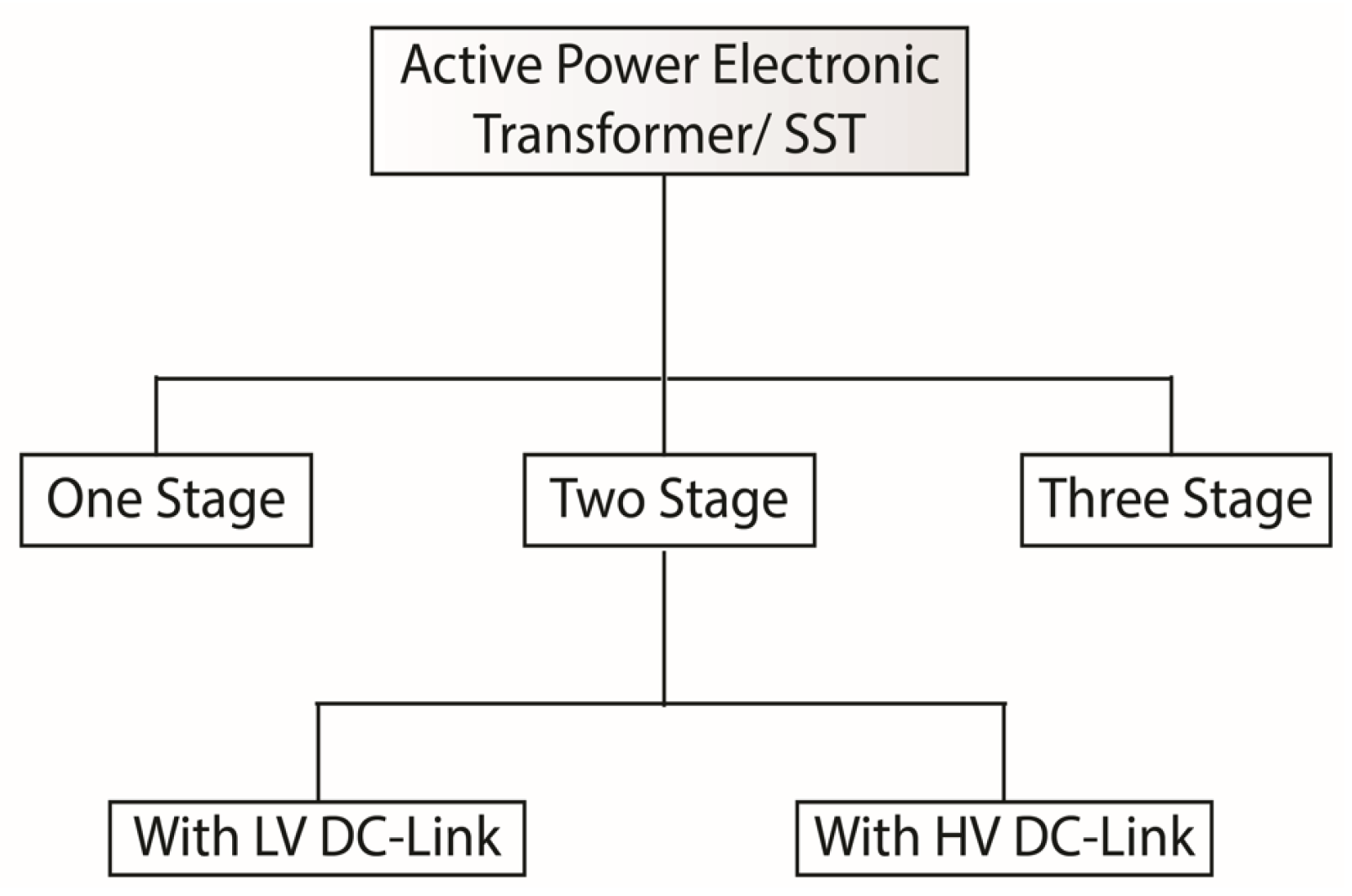
1.1. Single-Stage SST
1.2. Two-Stage SST
1.3. Three-Stage SST
2. Review of Related Works/Literature Appraisal
3. Critical Evaluation and Discussion
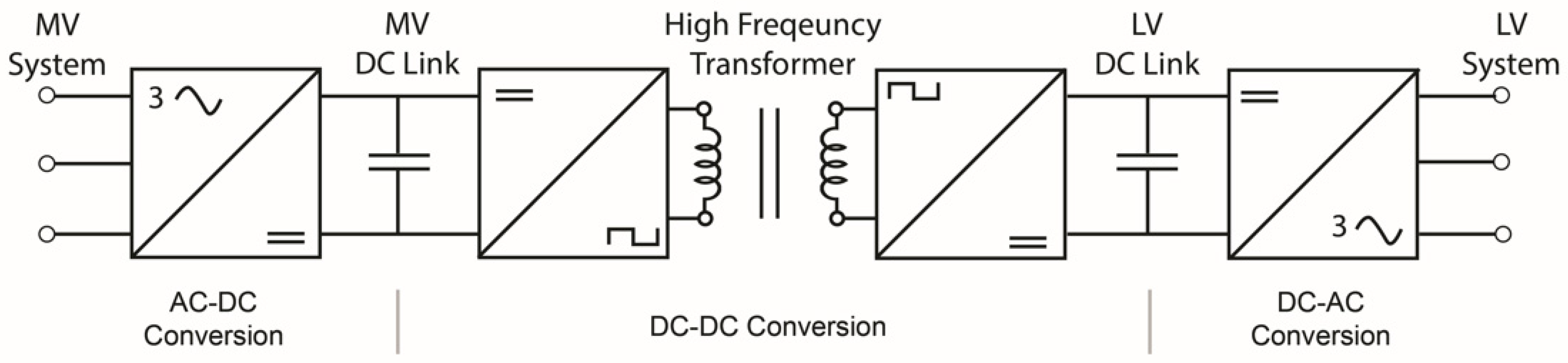
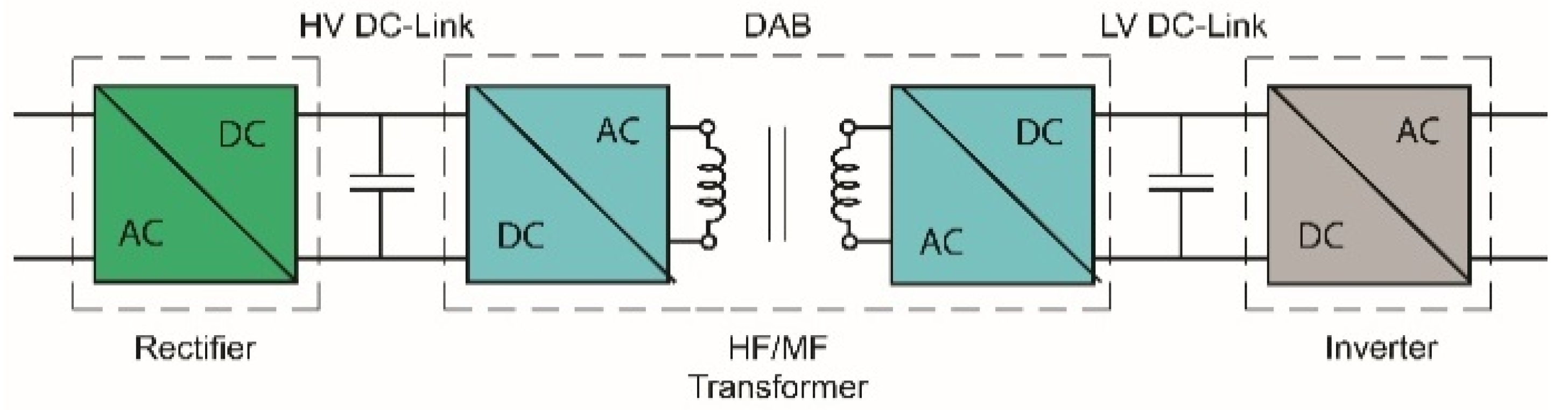
3.1. Solid State Transformer Architecture
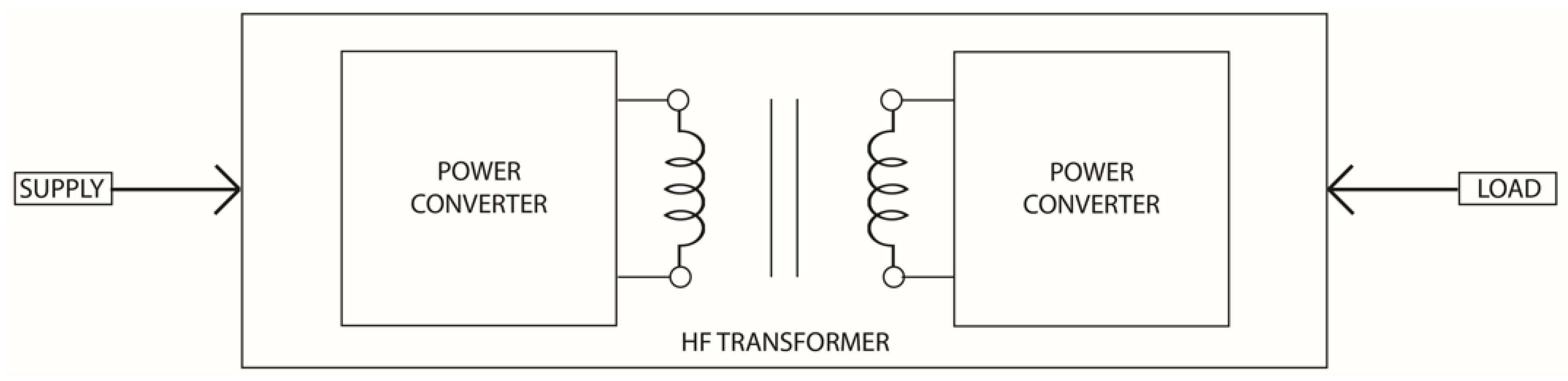
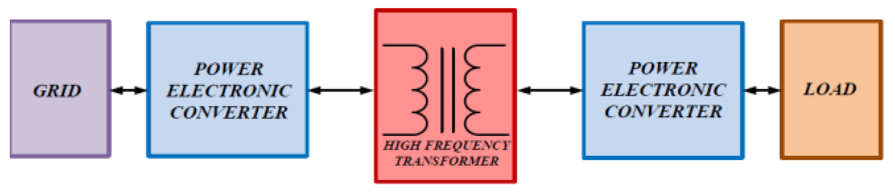
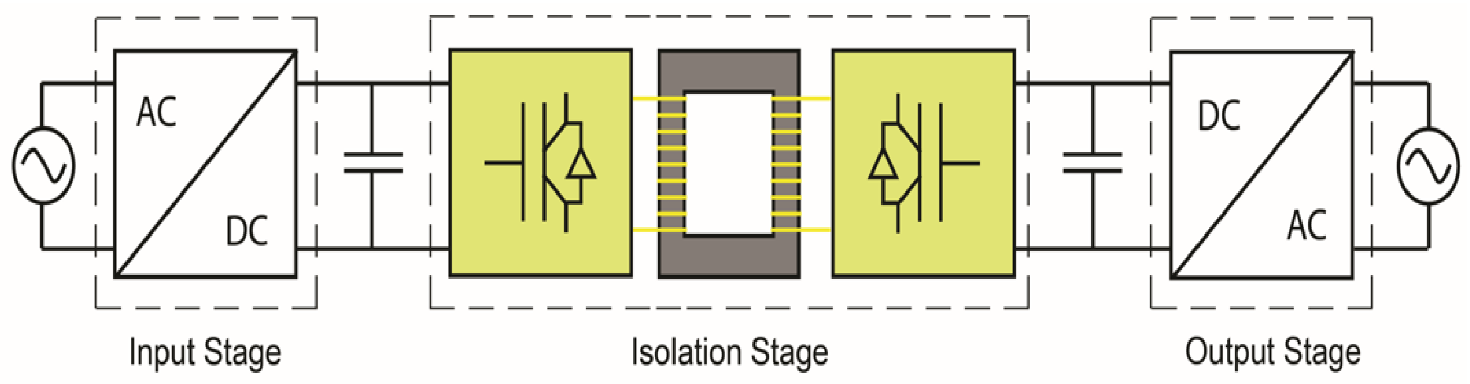
3.2. Transformer-Isolated DC-DC Converter
3.3. High Frequency DC-AC Inverter
3.4. Embryonic Development—HFHP Isolated DC-DC Module
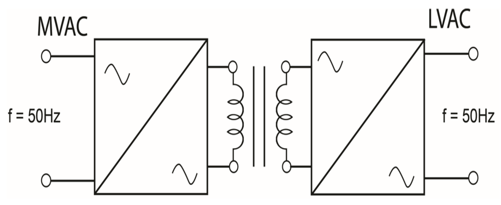
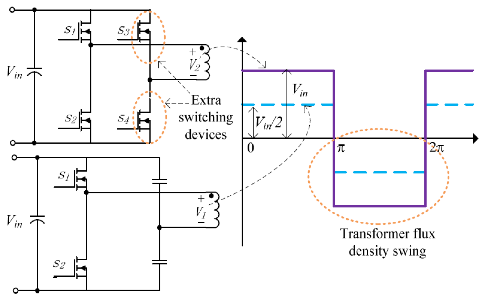
4. Transformer as Galvanic Isolator of the DAB/DHB
- Nano-crystalline (FT-3M): Possesses saturation flux density, Bmax,1.23 (T), Curie temperature Tc 570 (°C) and maximum operation temperature.150 (°C).
- Ferrite (3F3): Possesses saturation flux density, Bmax, 0.45 (T), Curie temperature Tc 200 (°C) and maximum operation temperature. 120 (°C).
- Super-alloy: Possesses saturation flux density, Bmax 0.79~0.87 (T), Curie temperature Tc 430 (°C) and maximum operation temperature. 125 (°C).
- Amorphous (2605SA): Possesses saturation flux density, Bmax 1.57(T), Curie temperature Tc 392 (°C) and maximum operation temperature. 150 (°C).
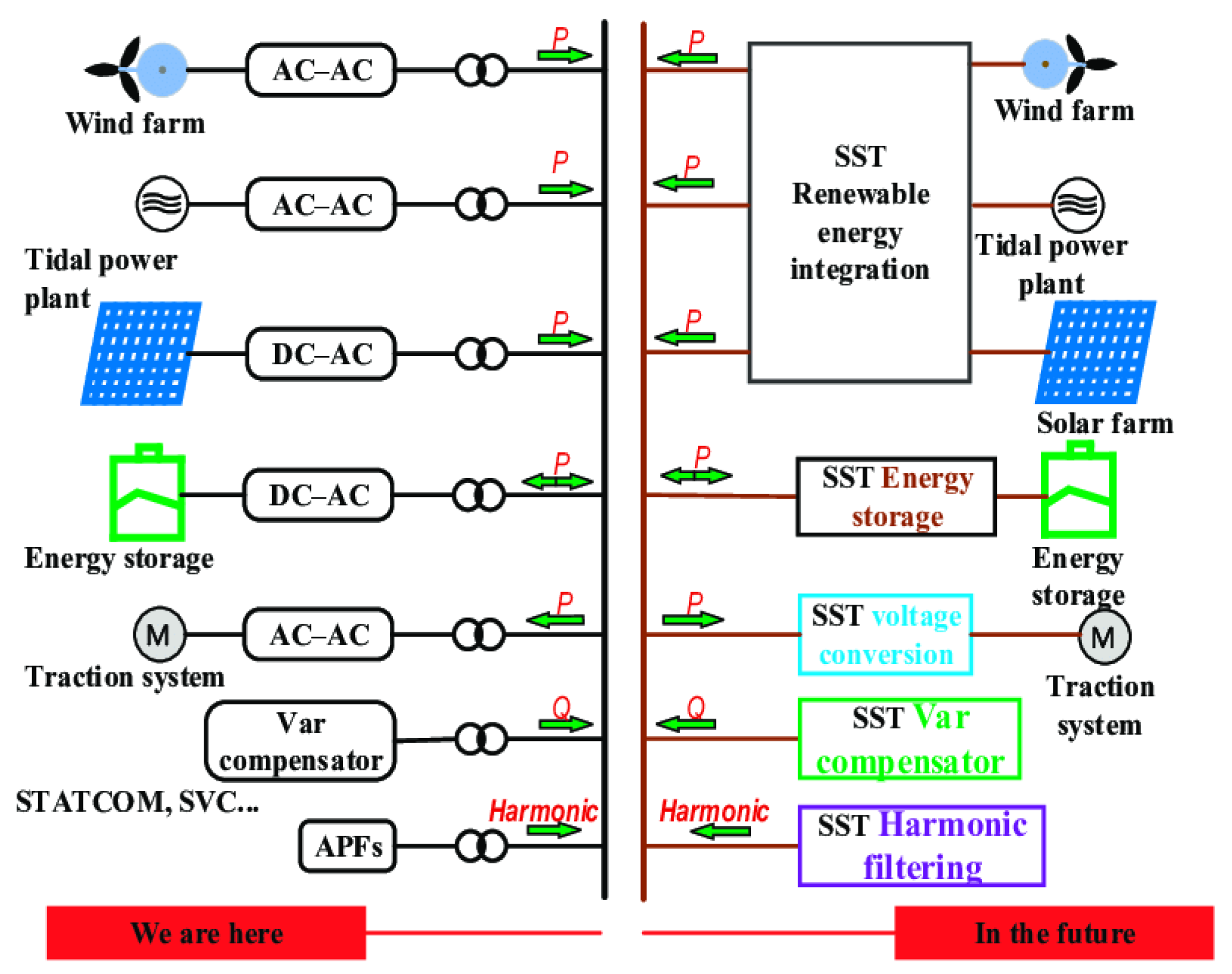
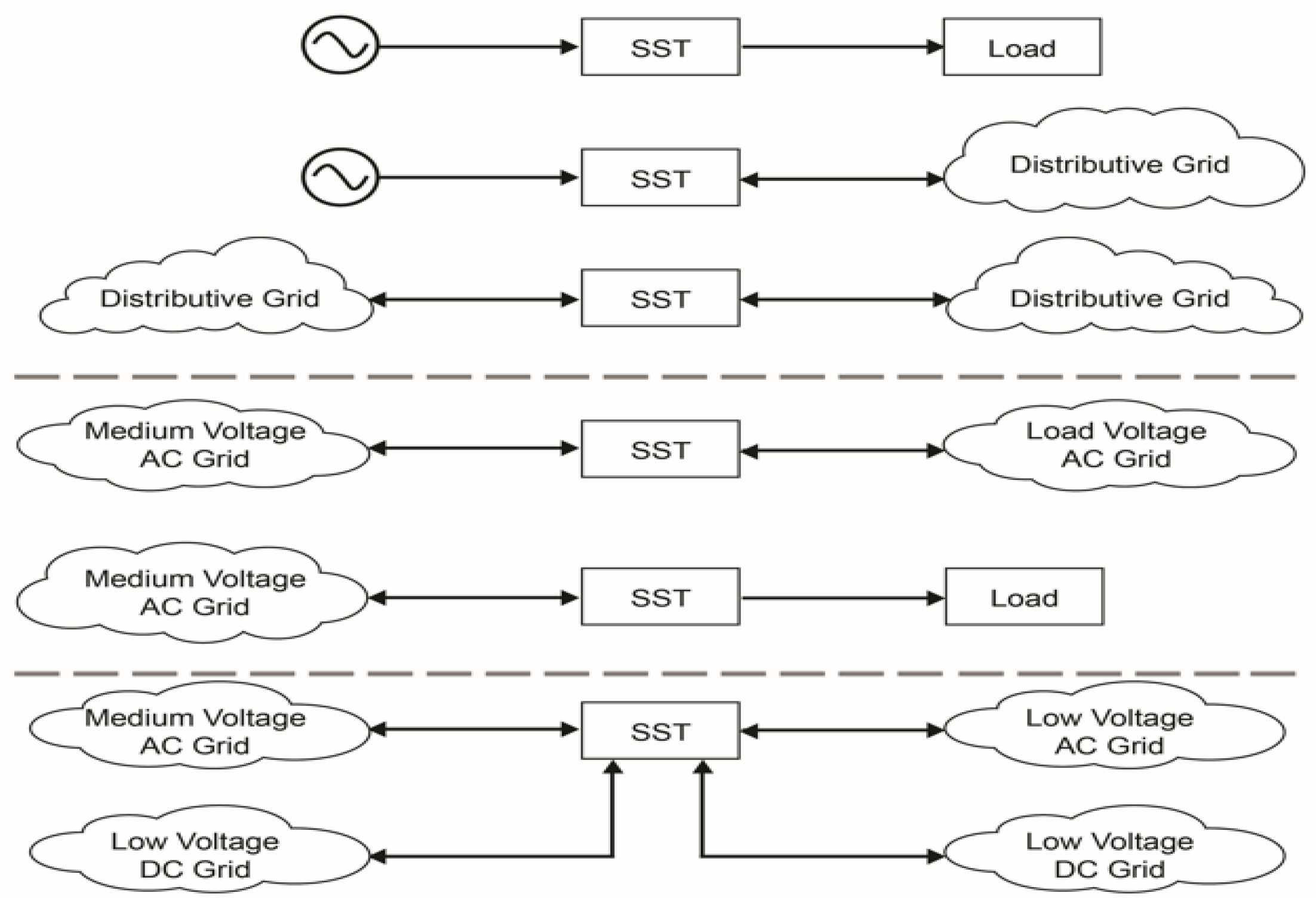
5. Applications of SST and DC-DC Converter
6. Conclusions
Author Contributions
Funding
Data Availability Statement
Conflicts of Interest
References
- Huber, J.E.; Kolar, J.W. Solid-State Transformers: On the Origins and Evolution of Key Concepts. IEEE Ind. Electron. Mag. 2016, 10, 19–28. [Google Scholar] [CrossRef]
- Acikgoz, H.; Kececioglu, O.F.; Yildiz, C.; Gani, A.; Sekkeli, M. Performance analysis of electronic power transformer based on neuro-fuzzy controller. SpringerPlus 2016, 5, 1350. [Google Scholar] [CrossRef]
- Heinemann, L.; Mauthe, G. The universal power electronics based distribution transformer, an unified approach. In Proceedings of the 2001 IEEE 32nd Annual Power Electronics Specialists Conference (IEEE Cat. No.01CH37230), Vancouver, BC, Canada, 17–21 June 2001; Volume 502, pp. 504–509. [Google Scholar]
- Roy, R.B.; Rokonuzzaman, M.; Hossam-E-Haider, M. Design and analysis of the power electronic transformer for power quality improvement. In Proceedings of the 2015 International Conference on Electrical Engineering and Information Communication Technology (ICEEICT), Dhaka, Bangladesh, 21–23 May 2015; pp. 1–5. [Google Scholar]
- Falcones, S.; Ayyanar, R.; Mao, X. A DC–DC Multiport-Converter-Based Solid-State Transformer Integrating Distributed Generation and Storage. IEEE Trans. Power Electron. 2013, 28, 2192–2203. [Google Scholar] [CrossRef]
- Ahmed, K.; Yahaya, N.Z.; Asirvadam, V.S.; Ibrahim, O. Modeling and Simulation of Power Electronic Distribution Transformer Based on a Three Level Converter. Appl. Mech. Mater. 2015, 785, 151–155. [Google Scholar] [CrossRef]
- Merwe, J.W.V.d.; Mouton, H.D.T. The solid-state transformer concept: A new era in power distribution. In Proceedings of the AFRICON 2009, Nairobi, Kenya, 23–25 September 2009; pp. 1–6. [Google Scholar]
- Zhao, T.; Wang, G.; Bhattacharya, S.; Huang, A.Q. Voltage and Power Balance Control for a Cascaded H-Bridge Converter-Based Solid-State Transformer. IEEE Trans. Power Electron. 2013, 28, 1523–1532. [Google Scholar] [CrossRef]
- Shadfar, H.; Ghorbani Pashakolaei, M.; Akbari Foroud, A. Solid-state transformers: An overview of the concept, topology, and its applications in the smart grid. Int. Trans. Electr. Energy Syst. 2021, 31, e12996. [Google Scholar] [CrossRef]
- Mcmurray, W. Power Converter Circuits Having A High Frequency Link. U.S. Patent No. 3,517,300, 23 June 1970. [Google Scholar]
- Pratik Mandon, A.P. Eswara Prasad. Solid State Transformer (SST) Market Outlook—2028. Available online: https://www.alliedmarketresearch.com/solid-state-transformer-market (accessed on 22 August 2022).
- Davis, S. Are Solid-State Transformers Ready for Prime Time? Available online: https://www.electronicdesign.com/technologies/alternative-energy/article/21199414/are-solidstate-transformers-ready-for-prime-time (accessed on 16 August 2022).
- Mumuluh, R.N. Design Considerations for a High Power, Medium Frequency Transformer for a DC-DC Converter Stage of a Solid State Transformer. Doctor’s Dissertation, University College Dublin, Dublin, Ireland, 2016. [Google Scholar]
- Hengsi, Q.; Kimball, J.W. Ac-ac dual active bridge converter for solid state transformer. In Proceedings of the 2009 IEEE Energy Conversion Congress and Exposition, San Jose, CA, USA, 20–24 September 2009; pp. 3039–3044. [Google Scholar]
- She, X.; Huang, A.Q.; Wang, G. 3-D Space Modulation with Voltage Balancing Capability for a Cascaded Seven-Level Converter in a Solid-State Transformer. IEEE Trans. Power Electron. 2011, 26, 3778–3789. [Google Scholar] [CrossRef]
- Beldjajev, V. Research and Development of the New Topologies for the Isolation Stage of the Power Electronic Transformer; Tallinn University of Technology: Tallinn, Estonia, 2013. [Google Scholar]
- Falcones, S.; Mao, X.; Ayyanar, R. Topology comparison for Solid State Transformer implementation. In Proceedings of the IEEE PES General Meeting, Minneapolis, MN, USA, 25–29 July 2010; pp. 1–8. [Google Scholar]
- Shojaei, A.; Joós, G. A topology for three-stage Solid State Transformer. In Proceedings of the 2013 IEEE Power & Energy Society General Meeting, Vancouver, BC, Canada, 21–25 July 2013; pp. 1–5. [Google Scholar]
- Dheeraj Reddy, D.S.K.S. Design of Solid State Transformer. Int. J. Adv. Res. Electr. Electron. Instrum. Eng. 2015, 357–364. [Google Scholar]
- Sharun John, B.N.R. Active power electronic transformer a standard building block for smart grid. In Proceedings of the International Journal of Electrical Engineering & Technology (IJEET), Ernakulam, India, 30–31 December 2014; pp. 178–184. [Google Scholar]
- She, X.; Yu, X.; Wang, F.; Huang, A.Q. Design and demonstration of a 3.6kV 2013;120V/10KVA solid state transformer for smart grid application. In Proceedings of the 2014 IEEE Applied Power Electronics Conference and Exposition—APEC 2014, Fort Worth, TX, USA, 16–20 March 2014; pp. 3429–3436. [Google Scholar]
- Wang, G.; Huang, X.; Wang, J.; Zhao, T.; Bhattacharya, S.; Huang, A.Q. Comparisons of 6.5kV 25A Si IGBT and 10-kV SiC MOSFET in Solid-State Transformer application. In Proceedings of the 2010 IEEE Energy Conversion Congress and Exposition, Atlanta, GA, USA, 12–16 September 2010; pp. 100–104. [Google Scholar]
- Aswathy Vijayakumar, R.R.N.; Stephy, J.; Mathew, S.; Keerthi, S.J. A Review on Active Power Electronic Transformer. Int. J. Mod. Trends Eng. Res. 2017, 4, 67–73. [Google Scholar]
- Ozdemir, S.; Balci, S.; Altin, N.; Sefa, I. Design and performance analysis of the three-level isolated DC-DC converter with the nanocyrstalline core transformer. Int. J. Hydrog. Energy 2017, 42, 17801–17812. [Google Scholar] [CrossRef]
- Srinithi, S.; Vaikundaselvan, B.; Sathya, S.N.; Sivan Raj, C. Hardware Implementation of Bidirectional Full Bridge Isolated DC- DC Converter. Int. J. Res. Electron. Electr. Eng. 2017, 3, 1–7. [Google Scholar] [CrossRef]
- Kim, S.; Cha, H.; Ahmed, H.F.; Choi, B.; Kim, H. Isolated Double Step-Down DC–DC Converter with Improved ZVS Range and No Transformer Saturation Problem. IEEE Trans. Power Electron. 2017, 32, 1792–1804. [Google Scholar] [CrossRef]
- Forouzesh, M.; Siwakoti, Y.P.; Gorji, S.A.; Blaabjerg, F.; Lehman, B. Step-Up DC–DC Converters: A Comprehensive Review of Voltage-Boosting Techniques, Topologies, and Applications. IEEE Trans. Power Electron. 2017, 32, 9143–9178. [Google Scholar] [CrossRef]
- Fan, H.; Li, H. High-Frequency Transformer Isolated Bidirectional DC–DC Converter Modules with High Efficiency Over Wide Load Range for 20 kVA Solid-State Transformer. IEEE Trans. Power Electron. 2011, 26, 3599–3608. [Google Scholar] [CrossRef]
- Dewangan, R.; Potdar, R. Comparative Analysis of Multilevel Inverter and Its PWM Schemes. Int. J. Dig. Appl. Contemp. Res. 2015, 4. Available online: https://ijdacr.com/uploads/papers/40300-15-005.pdf (accessed on 23 July 2022).
- Bharati Mishra, S.S.K. Design of an improved PWM inverter using PI controller. Int. J. Multidiscip. Res. Dev. 2016, 3, 92–95. [Google Scholar]
- Kalavalli, C.; Paveethra, S.; Murugesan, S.; Ali, N.; Venkatesh, V. Design And Implementation of High Efficiency H6 PV Inverter with Dual Axis Tracking. Int. J. Sci. Technol. Res. 2020, 9, 4728. [Google Scholar]
- Hyun, J.; Jung, J.-H. Practical Design of Dual Active Bridge Converter as Isolated Bi-directional Power Interface for Solid State Transformer Applications. J. Electr. Eng. Technol. 2016, 11, 1265–1273. [Google Scholar] [CrossRef]
- Harish Tata, P.M.S. A Literature Survey on Multilevel Inverter and its Parameter. Int. J. Eng. Technol. Appl. Sci. 2016, 2, 1–16. [Google Scholar]
- Raihani, A. Performance Evaluation for Different Levels Multilevel Inverters Application for Renewable Energy Resources. J. Eng. Technol. 2017, 6, 90–96. [Google Scholar]
- Akash Trivedi, S.; Rohan, A.; Mit, S.; Ankit, P. Design and Development of 3 Phase PWM Inverter. In Proceedings of the National Conference on Emerging Trends, Challenges & Opportunities in Power Sector, Ahmedabad, India, 3–4 March 2017; pp. 85–88. [Google Scholar]
- Gajowik, T. Review of multilevel converters for application in solid state transformers. Przegląd Elektrotechniczny 2017, 1, 3–7. [Google Scholar] [CrossRef][Green Version]
- PHANIKUMAR, A.B.; VALI, A.K. Renewable Energy Sources Based Single-Phase Seven Level Inverter Fed Induction Motor Drive. Int. J. Soc. Sci. Technol. 2017, 6, 1044–1049. [Google Scholar]
- Costa, L.F.; Buticchi, G.; Liserre, M. Optimum Design of a Multiple-Active-Bridge DC–DC Converter for Smart Transformer. IEEE Trans. Power Electron. 2018, 33, 10112–10121. [Google Scholar] [CrossRef]
- Ji, Z.; Rao, R.; Wang, Q.; Li, D.; Sun, Y.; Wang, J.; Zhao, J. Soft-starting scheme for a DC solid-state transformer based on a modular multilevel converter. Energy Rep. 2021, 7, 378–387. [Google Scholar] [CrossRef]
- Sathisha, K.; PintoPiusA, J. Comparison of two Different Approaches for Harmonic Analysis of Single Phase Inverter. Int. J. Innov. Res. Electr. Electron. Instrum. Control. Eng. 2017, 5, 1–6. [Google Scholar]
- Gao, Z.; Fan, H. A Modular Bi-Directional Power Electronic Transformer. J. Power Electron. 2016, 16, 399–413. [Google Scholar] [CrossRef]
- Chakraborty, S.; Chattopadhyay, S. Fully ZVS, Minimum RMS Current Operation of the Dual-Active Half-Bridge Converter Using Closed-Loop Three-Degree-of-Freedom Control. IEEE Trans. Power Electron. 2018, 33, 10188–10199. [Google Scholar] [CrossRef]
- Ling, C.; Ge, B.; Bi, D.; Ma, Q. An effective power electronic transformer applied to distribution system. In Proceedings of the 2011 International Conference on Electrical Machines and Systems, Beijing, China, 20–23 August 2011; pp. 1–6. [Google Scholar]
- Huang, A.; Crow, M.L.; Heydt, G.; Zheng, J.; Dale, S. The Future Renewable Electric Energy Delivery and Management (FREEDM) System: The Energy Internet. Proc. IEEE 2011, 99, 133–148. [Google Scholar] [CrossRef]
- Zhao, C.; Lewdeni-Schmid, S.; Steinke, J.K.; Weiss, M.; Chaudhuri, T.; Pellerin, M.; Duron, J.; Stefanutti, P. Design, implementation and performance of a modular power electronic transformer (PET) for railway application. In Proceedings of the Proceedings of the 2011 14th European Conference on Power Electronics and Applications, Birmingham, UK, 30 August–1 September 2011; pp. 1–10. [Google Scholar]
- Li, Z.; Wang, P.; Chu, Z.; Zhu, H.; Sun, Z.; Li, Y. A three-phase 10 kVAC-750 VDC power electronic transformer for smart distribution grid. In Proceedings of the 2013 15th European Conference on Power Electronics and Applications (EPE), Lille, France, 2–6 September 2013; pp. 1–9. [Google Scholar]
- Morawiec, M.; Lewicki, A.; Krzemiński, Z. Power Electronic Transformer for Smart Grid application. In Proceedings of the 2015 First Workshop on Smart Grid and Renewable Energy (SGRE), Doha, Qatar, 22–23 March 2015; pp. 1–6. [Google Scholar]
- Yun, H.J.; Kim, H.S.; Ryu, M.H.; Baek, J.W.; Kim, H.J. A simple and practical voltage balance method for a solid-state transformer using cascaded H-bridge converters. In Proceedings of the 2015 9th International Conference on Power Electronics and ECCE Asia (ICPE-ECCE Asia), Seoul, Korea, 1–5 June 2015; pp. 2415–2420. [Google Scholar]
- Ge, J.; Zhao, Z.; Yuan, L.; Lu, T. Energy Feed-Forward and Direct Feed-Forward Control for Solid-State Transformer. IEEE Trans. Power Electron. 2015, 30, 4042–4047. [Google Scholar] [CrossRef]
- Zhao, B.; Song, Q.; Liu, W. A Practical Solution of High-Frequency-Link Bidirectional Solid-State Transformer Based on Advanced Components in Hybrid Microgrid. IEEE Trans. Ind. Electron. 2015, 62, 4587–4597. [Google Scholar] [CrossRef]
- Madhusoodhanan, S.; Tripathi, A.; Patel, D.; Mainali, K.; Kadavelugu, A.; Hazra, S.; Bhattacharya, S.; Hatua, K. Solid-State Transformer and MV Grid Tie Applications Enabled by 15 kV SiC IGBTs and 10 kV SiC MOSFETs Based Multilevel Converters. IEEE Trans. Ind. Appl. 2015, 51, 3343–3360. [Google Scholar] [CrossRef]
- Chen, H.; Prasai, A.; Moghe, R.; Chintakrinda, K.; Divan, D. A 50-kVA Three-Phase Solid-State Transformer Based on the Minimal Topology: Dyna-C. IEEE Trans. Power Electron. 2016, 31, 8126–8137. [Google Scholar] [CrossRef]
- Nila-Olmedo, N.; Mendoza-Mondragon, F.; Espinosa-Calderon, A.; Moreno. ARM+FPGA platform to manage solid-state-smart transformer in smart grid application. In Proceedings of the 2016 International Conference on ReConFigurable Computing and FPGAs (ReConFig), Cancun, Mexico, 30 November–2 December 2016; pp. 1–6. [Google Scholar]
- Chen, H.; Divan, D. Soft-Switching Solid-State Transformer (S4T). IEEE Trans. Power Electron. 2018, 33, 2933–2947. [Google Scholar] [CrossRef]
- Liu, Y.; Ge, B.; Abu-Rub, H. Interactive Grid Interfacing System by Matrix-Converter-Based Solid State Transformer With Model Predictive Control. IEEE Trans. Ind. Inform. 2020, 16, 2533–2541. [Google Scholar] [CrossRef]
- She, X.; Huang, A.Q.; Burgos, R. Review of Solid-State Transformer Technologies and Their Application in Power Distribution Systems. IEEE J. Emerg. Sel. Top. Power Electron. 2013, 1, 186–198. [Google Scholar] [CrossRef]
- Zhao, C.; Dujic, D.; Mester, A.; Steinke, J.K.; Weiss, M.; Lewdeni-Schmid, S.; Chaudhuri, T.; Stefanutti, P. Power Electronic Traction Transformer—Medium Voltage Prototype. IEEE Trans. Ind. Electron. 2014, 61, 3257–3268. [Google Scholar] [CrossRef]
- Steiner, M.; Reinold, H. Medium frequency topology in railway applications. In Proceedings of the 2007 European Conference on Power Electronics and Applications, Aalborg, Denmark, 2–5 September 2007; pp. 1–10. [Google Scholar]
- Watson, A.J.; Wheeler, P.W.; Clare, J.C. Field programmable gate array based control of Dual Active Bridge DC/DC Converter for the UNIFLEX-PM project. In Proceedings of the 2011 14th European Conference on Power Electronics and Applications, Birmingham, UK, 30 August–1 September 2011; pp. 1–9. [Google Scholar]
- Liu, C.; Li, X.; Zhi, Y.; Cai, G. New breed of solid-state transformer mainly combing hybrid cascaded multilevel converter with resonant DC-DC converters. Appl. Energy 2018, 210, 724–736. [Google Scholar] [CrossRef]
- Huber, J.W.K.a.J.E. Solid-State Transformers Concepts, Challenges and Opportunities. In Proceedings of the ECPE Workshop—Smart Transformers for Traction and Future Grid Application, Zurich, Switzerland, 4–5 February2016. [Google Scholar]
- Pavlovsky, M.; Haan, S.W.H.d.; Ferreira, J.A. Concept of 50 kW DC/DC converter based on ZVS, quasi-ZCS topology and integrated thermal and electromagnetic design. In Proceedings of the 2005 European Conference on Power Electronics and Applications, Barcelona, Spain, 11–14 September 2005; p. 9. [Google Scholar]
- Bahmani, M.A.; Thiringer, T.; Kharezy, M. Optimization and experimental validation of medium-frequency high power transformers in solid-state transformer applications. In Proceedings of the 2016 IEEE Applied Power Electronics Conference and Exposition (APEC), Long Beach, CA, USA, 20–24 March 2016; pp. 3043–3050. [Google Scholar]
- Theraja, B.L. A Textbook of Electrical Technology Volume II AC and DC Machines; S. Chand Publishing: Uttar Pradesh, India, 2008. [Google Scholar]
- Andersson, C. Design of a 2.5kW DC/DC Fullbridge Converter; Chalmers University of Technology: Göteborg, Sweden, 2011. [Google Scholar]
- Lee, C.; Chen, Y.; Chen, L.; Cheng, P. Efficiency improvement of a DC/AC converter with the power decoupling capability. In Proceedings of the 2012 Twenty-Seventh Annual IEEE Applied Power Electronics Conference and Exposition (APEC), Orlando, FL, USA, 5–9 February 2012; pp. 1462–1468. [Google Scholar]
- Rathod, D.K. Solid State Transformer (SST) “Review of Recent Developments”. Proc. Adv. Electron. Electr. Eng. 2014, 4, 45–50. [Google Scholar]
- Engel, S.P.; Soltau, N.; Stagge, H.; Doncker, R.W.D. Dynamic and Balanced Control of Three-Phase High-Power Dual-Active Bridge DC–DC Converters in DC-Grid Applications. IEEE Trans. Power Electron. 2013, 28, 1880–1889. [Google Scholar] [CrossRef]
- Wang, F.; Duarte, J.; Hendrix, M. Design and analysis of active power control strategies for distributed generation inverters under unbalanced grid faults. Gener. Transm. Distrib. IET 2010, 4, 905–916. [Google Scholar] [CrossRef]
- Peng, F.Z.; Hui, L.; Gui-Jia, S.; Lawler, J.S. A new ZVS bidirectional DC-DC converter for fuel cell and battery application. IEEE Trans. Power Electron. 2004, 19, 54–65. [Google Scholar] [CrossRef]
- Cacciato, M.; Consoli, A.; Attanasio, R.; Gennaro, F. Soft-Switching Converter with HF Transformer for Grid-Connected Photovoltaic Systems. IEEE Trans. Ind. Electron. 2010, 57, 1678–1686. [Google Scholar] [CrossRef]
- Sangtaek, H.; Divan, D. Bi-directional DC/DC converters for plug-in hybrid electric vehicle (PHEV) applications. In Proceedings of the 2008 Twenty-Third Annual IEEE Applied Power Electronics Conference and Exposition, Austin, TX, USA, 24–28 February 2008; pp. 784–789. [Google Scholar]
- Inoue, S.; Akagi, H. A Bidirectional DC–DC Converter for an Energy Storage System with Galvanic Isolation. IEEE Trans. Power Electron. 2007, 22, 2299–2306. [Google Scholar] [CrossRef]
- Samad, M. Solid State Transformers: The State-of-the-Art, Challenges and Applications. In Proceedings of the Proceedings of the World Congress on Engineering, London, UK, 3–5 July 2019. [Google Scholar]
- Shamshuddin, M.A.; Rojas, F.; Cardenas, R.; Pereda, J.; Diaz, M.; Kennel, R. Solid State Transformers: Concepts, Classification, and Control. Energies 2020, 13, 2319. [Google Scholar] [CrossRef]
- Khan, S.; Rahman, K.; Tariq, M.; Hameed, S.; Alamri, B.; Babu, T.S. Solid-State Transformers: Fundamentals, Topologies, Applications, and Future Challenges. Sustainability 2022, 14, 319. [Google Scholar] [CrossRef]
- Huber, J.E.; Kolar, J.W. Volume/weight/cost comparison of a 1MVA 10 kV/400 V solid-state against a conventional low-frequency distribution transformer. In Proceedings of the 2014 IEEE Energy Conversion Congress and Exposition (ECCE), Pittsburgh, PA, USA, 14–18 September 2014; pp. 4545–4552. [Google Scholar]
- Ortiz, G.; Leibl, M.; Kolar, J.W.; Apeldoorn, O. Medium frequency transformers for solid-state-transformer applications—Design and experimental verification. In Proceedings of the 2013 IEEE 10th International Conference on Power Electronics and Drive Systems (PEDS), 22–25 April 2013; pp. 1285–1290. [Google Scholar]
- Meena, C.S.; Kumar, A.; Jain, S.; Rehman, A.U.; Mishra, S.; Sharma, N.K.; Bajaj, M.; Shafiq, M.; Eldin, E.T. Innovation in Green Building Sector for Sustainable Future. Energies 2022, 15, 6631. [Google Scholar] [CrossRef]
- Baek, S.; Bhattacharya, S. Analytical modeling of a medium-voltage and high-frequency resonant coaxial-type power transformer for a solid state transformer application. In Proceedings of the 2011 IEEE Energy Conversion Congress and Exposition, Phoenix, AZ, USA, 17–22 September 2011; pp. 1873–1880. [Google Scholar]
- Shen, W. Design of High-Density Transformers for High-Frequency High-Power Converters. Doctoral Dissertation, Virginia Polytechnic Institute and State University, Blacksburg, VA, USA, 2006. [Google Scholar]
- Kang, M.; Enjeti, P.N.; Pitel, I.J. Analysis and design of electronic transformers for electric power distribution system. IEEE Trans. Power Electron. 1999, 14, 1133–1141. [Google Scholar] [CrossRef]
- Rehman, A.; Ashraf, M. Design and Analysis of PWM Inverter for 100KVA Solid State Transformer in a Distribution System. IEEE Access 2019, 7, 140152–140168. [Google Scholar] [CrossRef]
- Fan, H. Advanced Medium-Voltage Bidirectional dc-dc Conversion Systems for Future Electric Energy Delivery and Management Systems; The Florida State University College of Engineering: Tallahassee, FL, USA, 2011. [Google Scholar]
- Pavlovsky, M.; de Haan, S.W.H.; Ferreira, J.A. Integral design of 50 kW, 25 kHz dc-dc Converter. In Proceedings of the 4th International Conference on Integrated Power Systems, Proceedings ZCS Topology, Naples, Italy, 7–9 June 2006; pp. 1–6. [Google Scholar]
- Ned Mohan, T.M.U.; William, P. Robbins. Power Electronics: Converters, Applications, and Design, 3rd ed.; John Wiley & Sons: Hoboken, NJ, USA, 2002; p. 832. [Google Scholar]
- Iyer, K.V.; Robbins, W.P.; Mohan, N. Winding design of a high power medium frequency transformer. In Proceedings of the 2014 International Symposium on Power Electronics, Electrical Drives, Automation and Motion, Ischia, Italy, 18–20 June 2014; pp. 665–669. [Google Scholar]
- Dincan, C.; Kaer, P. Control and modulation for loss minimization for dc/dc converter in wind farm. In Proceedings of the PCIM Europe 2016; International Exhibition and Conference for Power Electronics, Intelligent Motion, Renewable Energy and Energy Management, Nuremberg, Germany, 10–12 May 2016; pp. 1–8. [Google Scholar]
- Tariq, R.; Alhamrouni, I.; Rehman, A.U.; Tag Eldin, E.; Shafiq, M.; Ghamry, N.A.; Hamam, H. An Optimized Solution for Fault Detection and Location in Underground Cables Based on Traveling Waves. Energies 2022, 15, 6468. [Google Scholar] [CrossRef]
- Berasategi, A.; Cabal, C.; Alonso, C.; Estibals, B. European efficiency improvement in photovoltaic applications by means of parallel connection of power converters. In Proceedings of the 2009 13th European Conference on Power Electronics and Applications, Barcelona, Spain, 8–10 September 2009; pp. 1–10. [Google Scholar]
- Maqbool, H.; Yousaf, A.; Asif, R.M.; Rehman, A.U.; Eldin, E.T.; Shafiq, M.; Hamam, H. An Optimized Fuzzy Based Control Solution for Frequency Oscillation Reduction in Electric Grids. Energies 2022, 15, 6981. [Google Scholar] [CrossRef]
- Vinnikov, D.; Bolgov, V. Efficiency Optimization of the High-Power Isolated DC/DC Converters through THD and Losses Reduction in Isolation Transformers. Renew. Energy Power Qual. J. 2009, 1, 383–389. [Google Scholar] [CrossRef]
- Syed, I.; Khadkikar, V. Replacing the Grid Interface Transformer in Wind Energy Conversion System with Solid-State Transformer. IEEE Trans. Power Syst. 2017, 32, 2152–2160. [Google Scholar] [CrossRef]
- Mishra, D.K.; Ghadi, M.J.; Li, L.; Hossain, M.J.; Zhang, J.; Ray, P.K.; Mohanty, A. A review on solid-state transformer: A breakthrough technology for future smart distribution grids. Int. J. Electr. Power Energy Syst. 2021, 133, 107255. [Google Scholar] [CrossRef]
- Gupta, E.; Kumar Sinha, S.; Kumar Vates, U.; Chavan, S.S. A high performance solid state transformer for an efficient electric grid application: Design and analysis for advanced nanocrystalline core material. Mater. Today: Proc. 2021, 46, 2146–2149. [Google Scholar] [CrossRef]
- Wang, W.; Wang, X.; He, J.; Liu, Y.; Li, S.; Nie, Y. Electric stress and dielectric breakdown characteristics under high-frequency voltages with multi-harmonics in a solid-state transformer. Int. J. Electr. Power Energy Syst. 2021, 129, 106861. [Google Scholar] [CrossRef]
- Kabalcı, E. CHAPTER 9—Solid state transformers with multilevel inverters. In Multilevel Inverters; Kabalcı, E., Ed.; Academic Press: Cambridge, MA, USA, 2021; pp. 249–266. [Google Scholar]
- Kaliappan, G.; Rengaraj, M. Aging assessment of transformer solid insulation: A review. Mater. Today Proc. 2021, 47, 272–277. [Google Scholar] [CrossRef]
- Fetisov, Y.K.; Chashin, D.V. Magnetoelectric coil-free voltage transformer based on monolithic ferrite-piezoelectric heterostructure. Sens. Actuators A Phys. 2022, 344, 113737. [Google Scholar] [CrossRef]
- Oggier, G.G.; GarcÍa, G.O.; Oliva, A.R. Switching Control Strategy to Minimize Dual Active Bridge Converter Losses. IEEE Trans. Power Electron. 2009, 24, 1826–1838. [Google Scholar] [CrossRef]
- Guo, H.; Guo, L. Health index for power transformer condition assessment based on operation history and test data. Energy Rep. 2022, 8, 9038–9045. [Google Scholar] [CrossRef]
- Shah, D.G.; Crow, M.L. Stability Design Criteria for Distribution Systems with Solid-State Transformers. IEEE Trans. Power Deliv. 2014, 29, 14759118. [Google Scholar] [CrossRef]
- Wan, C.; Zou, J.; Tang, H.; Zhang, Q.; Wang, T. Investigation of a power network quality comprehensive control device based on novel cascaded power units. Int. Trans. Electr. Energy Syst. 2020, 30, e12651. [Google Scholar] [CrossRef]
- Vaca-Urbano, F.; Alvarez-Alvarado, M.S. Power quality with solid state transformer integrated smart-grids. In Proceedings of the 2017 IEEE PES Innovative Smart Grid Technologies Conference—Latin America (ISGT Latin America), Quito, Ecuador, 20–22 September 2017; pp. 1–6. [Google Scholar]
- Guo, Z.; Sha, D. Introduction. In New Topologies and Modulation Schemes for Soft-Switching Isolated DC–DC Converters; Guo, Z., Sha, D., Eds.; Springer: Singapore, 2020; pp. 1–21. [Google Scholar]
- Wu, K.; Silva, C.W.d.; Dunford, W.G. Stability Analysis of Isolated Bidirectional Dual Active Full-Bridge DC–DC Converter with Triple Phase-Shift Control. IEEE Trans. Power Electron. 2012, 27, 2007–2017. [Google Scholar] [CrossRef]
- Jain, A.K.; Ayyanar, R. Pwm control of dual active bridge: Comprehensive analysis and experimental verification. IEEE Trans. Power Electron. 2011, 26, 1215–1227. [Google Scholar] [CrossRef]
- Zhabelova, G.; Yavarian, A.; Vyatkin, V.; Huang, A.Q. Data center energy efficiency and power quality: An alternative approach with solid state transformer. In Proceedings of the IECON 2015—41st Annual Conference of the IEEE Industrial Electronics Society, Yokohama, Japan, 9–12 November 2015; pp. 1294–1300. [Google Scholar]
- Huber, J.E.; Böhler, J.; Rothmund, D.; Kolar, J.W. Analysis and cell-level experimental verification of a 25 kW all-SiC isolated front end 6.6 kV/400 V AC-DC solid-state transformer. CPSS Trans. Power Electron. Appl. 2017, 2, 140–148. [Google Scholar] [CrossRef]
- Kim, M.; Rosekeit, M.; Sul, S.K.; Doncker, R.W.A.A.D. A dual-phase-shift control strategy for dual-active-bridge DC-DC converter in wide voltage range. In Proceedings of the 8th International Conference on Power Electronics—ECCE Asia, Jeju, Korea, 30 May–3 June 2011; pp. 364–371. [Google Scholar]
- Zhao, B.; Song, Q.; Liu, W.; Liu, G.; Zhao, Y. Universal High-Frequency-Link Characterization and Practical Fundamental-Optimal Strategy for Dual-Active-Bridge DC-DC Converter Under PWM Plus Phase-Shift Control. IEEE Trans. Power Electron. 2015, 30, 6488–6494. [Google Scholar] [CrossRef]
- Gorla, N.B.Y.; Kolluri, S.; Chai, M.; Panda, S.K. A Comprehensive Harmonic Analysis and Control Strategy for Improved Input Power Quality in a Cascaded Modular Solid State Transformer. IEEE Trans. Power Electron. 2019, 34, 6219–6232. [Google Scholar] [CrossRef]
- Samejima, T.; Kintsu, K.; Morizane, T.; Kimura, N. Comparison of core material of high frequency transformer for offshore wind generation. In Proceedings of the 2018 International Symposium on Power Electronics, Electrical Drives, Automation and Motion (SPEEDAM), Sorrento, Italy, 20–22 June 2018; pp. 348–352. [Google Scholar]
- Khosa, I.; Taimoor, N.; Akhtar, J.; Ali, K.; Rehman, A.U.; Bajaj, M.; Elgbaily, M.; Shouran, M.; Kamel, S. Financial Hazard Assessment for Electricity Suppliers Due to Power Outages: The Revenue Loss Perspective. Energies 2022, 15, 4327. [Google Scholar] [CrossRef]
- Mirza, A.F.; Haider, S.K.; Ahmed, A.; Rehman, A.U.; Shafiq, M.; Bajaj, M.; Zawbaa, H.M.; Szczepankowski, P.; Kamel, S. Generalized regression neural network and fitness dependent optimization: Application to energy harvesting of centralized TEG systems. Energy Rep. 2022, 8, 6332–6346. [Google Scholar] [CrossRef]
- Masood, B.; Guobing, S.; Nebhen, J.; Rehman, A.U.; Iqbal, M.N.; Rasheed, I.; Bajaj, M.; Shafiq, M.; Hamam, H. Investigation and Field Measurements for Demand Side Management Control Technique of Smart Air Conditioners located at Residential, Commercial, and Industrial Sites. Energies 2022, 15, 2482. [Google Scholar] [CrossRef]
- Sarwar, S.; Javed, M.Y.; Jaffery, M.H.; Arshad, J.; Ur Rehman, A.; Shafiq, M.; Choi, J.-G. A Novel Hybrid MPPT Technique to Maximize Power Harvesting from PV System under Partial and Complex Partial Shading. Appl. Sci. 2022, 12, 587. [Google Scholar] [CrossRef]
- Sharma, H.; Mishra, S.; Dhillon, J.; Sharma, N.K.; Bajaj, M.; Tariq, R.; Rehman, A.U.; Shafiq, M.; Hamam, H. Feasibility of Solar Grid-Based Industrial Virtual Power Plant for Optimal Energy Scheduling: A Case of Indian Power Sector. Energies 2022, 15, 752. [Google Scholar] [CrossRef]
- Daniel, K.; Kütt, L.; Iqbal, M.N.; Shabbir, N.; Rehman, A.U.; Shafiq, M.; Hamam, H. Current Harmonic Aggregation Cases for Contemporary Loads. Energies 2022, 15, 437. [Google Scholar] [CrossRef]
- Kshatri, S.; Dhillon, J.; Mishra, S.; Tariq, R.; Sharma, N.; Bajaj, M.; Rehman, A.; Choi, J.-G. Reliability Analysis of Bifacial PV Panel-Based Inverters Considering the Effect of Geographical Location. Energies 2021, 15, 170. [Google Scholar] [CrossRef]
- Shabbir, N.; Kütt, L.; Jawad, M.; Husev, O.; Rehman, A.; Gardezi, A.; Choi, J.-G. Short-Term Wind Energy Forecasting Using Deep Learning-Based Predictive Analytics. Comput. Mater. Contin. 2022, 72, 1017–1033. [Google Scholar] [CrossRef]
- Khalid, A.; Jaffery, M.H.; Javed, M.Y.; Yousaf, A.; Arshad, J.; Ur Rehman, A.; Haider, A.; Althobaiti, M.M.; Shafiq, M.; Hamam, H. Performance Analysis of Mars-Powered Descent-Based Landing in a Constrained Optimization Control Framework. Energies 2021, 14, 8493. [Google Scholar] [CrossRef]
- Ehsan, U.; Jawad, M.; Javed, U.; Shabih Zaidi, K.; Ur Rehman, A.; Rassõlkin, A.; Althobaiti, M.M.; Hamam, H.; Shafiq, M. A Detailed Testing Procedure of Numerical Differential Protection Relay for EHV Auto Transformer. Energies 2021, 14, 8447. [Google Scholar] [CrossRef]
- Choudhury, S.; Acharya, S.K.; Khadanga, R.K.; Mohanty, S.; Arshad, J.; Ur Rehman, A.; Shafiq, M.; Choi, J.-G. Harmonic Profile Enhancement of Grid Connected Fuel Cell through Cascaded H-Bridge Multi-Level Inverter and Improved Squirrel Search Optimization Technique. Energies 2021, 14, 7947. [Google Scholar] [CrossRef]
- Yousaf, A.; Asif, R.M.; Shakir, M.; Rehman, A.U.; Alassery, F.; Hamam, H.; Cheikhrouhou, O. A Novel Machine Learning-Based Price Forecasting for Energy Management Systems. Sustainability 2021, 13, 12693. [Google Scholar] [CrossRef]
- Rafique, W.; Khan, A.; Almogren, A.; Arshad, J.; Yousaf, A.; Jaffery, M.; Rehman, A. Adaptive Fuzzy Logic Controller for Harmonics Mitigation Using Particle Swarm Optimization. Comput. Mater. Contin. 2022, 71, 4275–4293. [Google Scholar] [CrossRef]
- Rizwan, R.; Arshad, J.; Almogren, A.; Jaffery, M.H.; Yousaf, A.; Khan, A.; Ur Rehman, A.; Shafiq, M. Implementation of ANN-Based Embedded Hybrid Power Filter Using HIL-Topology with Real-Time Data Visualization through Node-RED. Energies 2021, 14, 7127. [Google Scholar] [CrossRef]
- Khan, A.; Jaffery, M.H.; Javed, Y.; Arshad, J.; Rehman, A.U.; Khan, R.; Bajaj, M.; Kaabar, M.K.A. Hardware-in-the-Loop Implementation and Performance Evaluation of Three-Phase Hybrid Shunt Active Power Filter for Power Quality Improvement. Math. Probl. Eng. 2021, 2021, 8032793. [Google Scholar] [CrossRef]
- Dashtdar, M.; Bajaj, M.; Hosseinimoghadam, S.M.S.; Sami, I.; Choudhury, S.; Rehman, A.U.; Goud, B.S. Improving voltage profile and reducing power losses based on reconfiguration and optimal placement of UPQC in the network by considering system reliability indices. Int. Trans. Electr. Energy Syst. 2021, 31, e13120. [Google Scholar] [CrossRef]
- Arshad, J.; Khan, A.; Aftab, M.; Hussain, M.; Rehman, A.; Ahmad, S.; Al-Shayea, A. Deep Deterministic Policy Gradient to Regulate Feedback Control Systems Using Reinforcement Learning. Comput. Mater. Contin. 2021, 71, 1153–1169. [Google Scholar] [CrossRef]
- Jakka, V.N.; Acharya, S.; Anurag, A.; Prabowo, Y.; Kumar, A.; Parashar, S.; Bhattacharya, S. Protection Design Considerations of a 10 kV SiC MOSFET Enabled Mobile Utilities Support Equipment Based Solid State Transformer (MUSE-SST). In Proceedings of the IECON 2018—44th Annual Conference of the IEEE Industrial Electronics Society, Washington, DC, USA, 21–23 October 2018; pp. 5559–5565. [Google Scholar]
- Tudorache, T.; Marinescu, A.; Dumbrava, I. On-road Charging System Demonstrator for EVs. In Proceedings of the 2019 Electric Vehicles International Conference (EV), Bucharest, Romania, 3–4 October 2019; pp. 1–4. [Google Scholar]
- Pool-Mazun, E.I.; Sandoval, J.J.; Enjeti, P.N.; Pitel, I.J. An Integrated Solid-State Transformer with High-Frequency Isolation for EV Fast-Charging Applications. IEEE J. Emerg. Sel. Top. Ind. Electron. 2020, 1, 46–56. [Google Scholar] [CrossRef]
- Zhao, H.; Yang, B. A Novel Conception for HVDC Transmission Capacity Expansion and Its Control Strategy. In Proceedings of the 2018 IEEE International Power Electronics and Application Conference and Exposition (PEAC), Shenzhen, China, 4–7 November 2018; pp. 1–6. [Google Scholar]
- Kimura, N.; Morizane, T.; Iyoda, I.; Nakao, K.; Yokoyama, T. Application of Solid-State Transformer for HVDC Transmission from Offshore Windfarm. In Proceedings of the 2018 7th International Conference on Renewable Energy Research and Applications (ICRERA), Paris, France, 14–17 October 2018; pp. 902–907. [Google Scholar]
- Zapico, A.; Lopez, M.; Rodriguez, A.; Briz, F. Fault tolerant cell design for MMC-based multiport power converters. In Proceedings of the 2016 IEEE Energy Conversion Congress and Exposition (ECCE), Milwaukee, WI, USA, 18–22 September 2016; pp. 1–8. [Google Scholar]
- Gu, Z.; Gu, C.; Zhu, M.; Zhu, W.; Li, Z.; Xu, R.; Wang, J. Influence of temperature on frequency domain spectroscopy detection of transformer bushings. Energy Rep. 2022, 8, 381–387. [Google Scholar] [CrossRef]
- Hannan, M.A.; Ker, P.J.; Lipu, M.S.H.; Choi, Z.H.; Rahman, M.S.A.; Muttaqi, K.M.; Blaabjerg, F. State of the Art of Solid-State Transformers: Advanced Topologies, Implementation Issues, Recent Progress and Improvements. IEEE Access 2020, 8, 19113–19132. [Google Scholar] [CrossRef]
- Foureaux, N.C.; Adolpho, L.; Silva, S.M.; Brito, J.A.d.S.; Filho, B.d.J.C. Application of solid state transformers in utility scale solar power plants. In Proceedings of the 2014 IEEE 40th Photovoltaic Specialist Conference (PVSC), Denver, CO, USA, 8–13 June 2014; pp. 3695–3700. [Google Scholar]
- Tafti, H.D.; Shuyu, C.; Kishore, K.V.R.; Farivar, G.; Yeo, H.L.; Sriram, V.B.; Pou, J.; Tripathi, A. Control of active front-end rectifier of the solid-state transformer with improved dynamic performance during precharging. In Proceedings of the 2017 Asian Conference on Energy, Power and Transportation Electrification (ACEPT), Singapore, 24–26 October 2017; pp. 1–6. [Google Scholar]
- Ronanki, D.; Kelkar, A.; Williamson, S.S. Extreme Fast Charging Technology—Prospects to Enhance Sustainable Electric Transportation. Energies 2019, 12, 3721. [Google Scholar] [CrossRef]
- Valedsaravi, S.; El Aroudi, A.; Martínez-Salamero, L. Review of Solid-State Transformer Applications on Electric Vehicle DC Ultra-Fast Charging Station. Energies 2022, 15, 5602. [Google Scholar] [CrossRef]
- Das, D.; Kumar, C. Operation and control of smart transformer based distribution grid in a microgrid system. In Proceedings of the 2017 National Power Electronics Conference (NPEC), Pune, India, 18–20 December 2017; pp. 135–140. [Google Scholar]
- Huber, J.W.K.J.E. Potential future applications and topologies of solid-state transformers (SSTs). In Proceedings of the ECPE 2019 Solid-State Transformer Workshop, Lausanne, Switzerland, 14 February 2019. [Google Scholar]
- Chen, H.; Divan, D. Design of a 10-kV·A Soft-Switching Solid-State Transformer (S4T). IEEE Trans. Power Electron. 2018, 33, 5724–5738. [Google Scholar] [CrossRef]
- Wang, H.; Zhang, Y.; Sun, Y.; Zheng, M.; Liang, X.; Zhang, G.; Tan, K.; Feng, J. Topology and Control Method of a Single-Cell Matrix-Type Solid-State Transformer. IEEE J. Emerg. Sel. Top. Power Electron. 2020, 8, 2302–2312. [Google Scholar] [CrossRef]
- Zhang, J.; Liu, J.; Yang, J.; Zhao, N.; Wang, Y.; Zheng, T.Q. An LLC-LC Type Bidirectional Control Strategy for an LLC Resonant Converter in Power Electronic Traction Transformer. IEEE Trans. Ind. Electron. 2018, 65, 8595–8604. [Google Scholar] [CrossRef]
- Liang, X.; Srdic, S.; Won, J.; Aponte, E.; Booth, K.; Lukic, S. A 12.47 kV Medium Voltage Input 350 kW EV Fast Charger using 10 kV SiC MOSFET. In Proceedings of the 2019 IEEE Applied Power Electronics Conference and Exposition (APEC), Orlando, FL, USA, 17–21 March 2019; pp. 581–587. [Google Scholar]
- Lahooti Eshkevari, A.; Mosallanejad, A.; Sepasian, M. In-depth study of the application of solid-state transformer in design of high-power electric vehicle charging stations. IET Electr. Syst. Transp. 2020, 10, 310–319. [Google Scholar] [CrossRef]
- Cittanti, D.; Gregorio, M.; Bossotto, E.; Mandrile, F.; Bojoi, R. Full Digital Control and Multi-Loop Tuning of a Three-Level T-Type Rectifier for Electric Vehicle Ultra-Fast Battery Chargers. Electronics 2021, 10, 1453. [Google Scholar] [CrossRef]
- Shafiei, M.; Ghasemi-Marzbali, A. Fast-charging station for electric vehicles, challenges and issues: A comprehensive review. J. Energy Storage 2022, 49, 104136. [Google Scholar] [CrossRef]
- Yousaf, A.; Asif, R.M.; Shakir, M.; Rehman, A.U.; Adrees, M. An Improved Residential Electricity Load Forecasting Using a Machine-Learning-Based Feature Selection Approach and a Proposed Integration Strategy. Sustainability 2021, 13, 6199. [Google Scholar] [CrossRef]
- Bakar Siddique, M.A.; Asad, A.; Asif, R.M.; Rehman, A.U.; Sadiq, M.T.; Ullah, I. Implementation of Incremental Conductance MPPT Algorithm with Integral Regulator by Using Boost Converter in Grid-Connected PV Array. IETE J. Res. 2021, 1–14. [Google Scholar] [CrossRef]
- Masood, B.; Guobing, S.; Naqvi, R.A.; Rasheed, M.B.; Hou, J.; Rehman, A.U. Measurements and channel modeling of low and medium voltage NB-PLC networks for smart metering. IET Gener. Transm. Distrib. 2021, 15, 321–338. [Google Scholar] [CrossRef]
- Masood, B.; Khan, M.A.; Baig, S.; Song, G.; Rehman, A.U.; Rehman, S.U.; Asif, R.M.; Rasheed, M.B. Investigation of Deterministic, Statistical and Parametric NB-PLC Channel Modeling Techniques for Advanced Metering Infrastructure. Energies 2020, 13, 3098. [Google Scholar] [CrossRef]
- Rehman, A. Design of High Frequency PWM Inverter as a Part of 100kVA Solid State Transformer; Capital City University: Islamabad, Pakistan, 2022. [Google Scholar]


| Parameter | Single-Stage (AC to AC Conversion) | Two-Stage Using LVDC Link | Two-Stage Using HVDC Link | Three-Stage with Both HVDC and LVDC Links |
|---|---|---|---|---|
| Input Power Factor Correction | No | Yes | Yes | Yes |
| DC Link Provision | No | Yes | Yes | Yes |
| Galvanic Isolation from Grid | Yes | Yes | Yes | Yes |
| DES and DER Management | No | Yes | Yes | Yes |
| Feasibility in SST applications | No | No | No | Yes |
| Cost and Weight | Lowest | Lower | Lower | Low |
| Input Voltage Regulation | No | Good | Good | Very Good |
| Reactive Power Compensation | None | Sure | Sure | Sure |
| Circuit Implementation | Easy | Easy | Easy | Easy |
| Ride-Through Capability of the SST | No | No | No | Yes |
| Power Quality Improvement | No | Yes | Yes | Yes |
| Input Current Limiting | No | Yes | Yes | Yes |
| Load (Ω) (Each Phase) | Input Voltage (V) (Each Phase) | Input Current (A) (Each Phase) | Input Power (W) (Each Phase) | Output Voltage (V) (Each Phase) | Load Current (A) (Each Phase) | Output Power (W) (in Each Phase) | Efficiency Each Phase) % |
|---|---|---|---|---|---|---|---|
| 100 | 5000 | 12.47 | 62,320 | 2494 | 24.94 | 62,180 | 99.77 |
| 200 | 5000 | 6.242 | 31,210 | 2497 | 12.48 | 31,170 | 99.88 |
| 500 | 5000 | 2.499 | 12,500 | 2499 | 4.997 | 12,490 | 99.94 |
| 1000 | 5000 | 1.25 | 6251 | 2499 | 2.499 | 6247 | 99.94 |
| 2000 | 5000 | 0.6254 | 3127 | 2500 | 1.25 | 3124 | 99.91 |
| 3000 | 5000 | 0.4171 | 2086 | 2500 | 0.833 | 2083 | 99.87 |
| 4000 | 5000 | 0.313 | 1585 | 2500 | 0.625 | 1582 | 99.83 |
| 5000 | 5000 | 0.2505 | 1252 | 2500 | 0.5 | 1250 | 99.79 |
| Writer/Year | Rating/ Specification | Topology/Configuration | Operational Effects/Results | Observation/Attainments |
|---|---|---|---|---|
| Brooks et al. (1980) | - | Single-stage, AC-AC (Step Down Conversion) | Reduce the input/applied voltage to a lower value at the output |
|
| Resischi et al. (1995) | - | Single-stage, AC-AC(Step Down Conversion) |
|
|
| Harada. (1996) | - | Single-stage, (HF AC link) |
| No arrangement for instantaneous voltage regulation as well as for voltage sag compensation |
| Kang et al. (1999) | - | Three-stage (High Frequency AC link) |
|
|
| J. Edward et al. (2000) Ronan et al. (2002) | 10 kVA, 7.2 kV/240 V | Three-stage Cascaded H-Bridge (High Frequency AC link) |
|
|
| Jih-Sheng et al. (2005) | - | Three-stage (High Frequency AC link) | Provision of PQ functions, galvanic isolation and isolation of a disturbance from either source or load | Different voltage Rising cost but with appreciable efficiency |
| J. Ai-Juan et al. (2006) | 5 kVA, 220 V/380 V | Two-stage, (AC/AC HF link) | Unbalanced linear load/input voltage | Lower THD |
| J. S. Lai et al. (2006) | 50 kVA, 2.4 kV/240 V/120 V | Three-stage (3 level NPC in MV side) |
|
|
| Iman et al. (2006) | High Frequency DC link | PF improvement, protection of critical loads and energy storage system | Use of numerous PE converter and DC link electrolytic capacitors | |
| Iman-Eini et al. (2008) | Single-phase, three-stage, (cascaded H-bridge) | Power factor improve-ment, protection of critical loads and energy storage system | Low efficiency and reliability | |
| H. Iman-Eini et al. (2009) | 1.5 kW, 230 V/39 V | Three-stage, (Cascaded H-bridge) | Voltage sag Nonlinear load | Harmonic voltage and reactive Power compensation. |
| Maitra et al. (2009) | High Frequency DC link | Maintain the source voltage balance among different modules | Lesser efficiency due to a number of components | |
| M. Sabahi et al. (2010) | 2 kW, 110 V/20 V | Single-stage (AC to AC Conver-sion) | Steady state response |
|
| S. B.Yu Du et al. (2010) | 20 kVA, 7.2 kV/240 V | Three-stage, (Cascaded H-Bridge) | Steady state response |
|
| Ling et al. (2011) | High Frequency DC link | Reduction in voltage stress Rating of components | Lower efficiency | |
| Jie Zeng et al. (2011) | High Frequency AC link | Core loss calculated as 81 W | Efficiency of the SST up to 96.6% (from half to full load) | |
| C. Zhao et al. (2011) | 1.2 MVA, 15 kV/16.7 Hz | Two-stage, (Cascaded H-bridge) | Steady state response | Bi-directional power flow |
| X. Liu et al. (2012) | 1 kW, 208 V/120 V | Three-stage (Two Level) | Steady state response | Bi-directional power flow |
| Subramanya (2012). | - | Three-stage AC-AC (Matrix converter based SST HF DC link) | Reduction in number of components | Escalating efficiency, with reduction in PQ with the voltage stress factor |
| Xinyu et al. (2012) | - | 3Φ, single-stage (Matrix converter for PET HF AC link) | Voltage regulation is 0.5–1 | Higher THD |
| Z. Li et al. (2013) | 110 kV AC-750 V DC | Two-stage, (AC/DC/DC, MMC) | Steady state response | Bi-directional power flow |
| Xu She et al. (2014) | 3.6 kV-120 V/10 kVA | Three-stage (FB, HF AC link) | Accessibility for ac as well as DC outputs | Efficiency ranges from 84% to 88% |
| M. Morawiec et al. (2015) | 600 kVA, 3.3 kV DC/ 3.3 kV DC | Three-stage, (Cascaded H-bridge in MV side) | Steady state response | Bi-directional power flow |
| H. J. Yun et al. (2015) | 5 kW, 300 Vac /380 V DC | Two-stage, (Cascaded H-bridge) | Steady state response | Bi-directional power flow |
| J. Ge et al. (2015) | 2 kW, 300 V/60 V | Three-stage (two-level) |
| Bi-directional power flow |
| B. Zhao et al. (2015) | 2 kVA, 380 V/120 V | Three-stage, (cascaded) |
| Bi-directional power flow |
| Madhusoodha-nan et al. (2015) | 5.8 KVA, 5 kV DC/800 V DC | Three-stage, (NPC) | Steady state response | Bi-directional power flow |
| Swapni et al. (2016). | - | Three-stage (High Frequency AC link) | Capability to substitute the old version conventional transformer |
|
| H. Chen et al. (2016) | 50 kVA, 480 V/480 V | Single-stage, Dyna-C (AC-AC) | Steady state response | Bi-directional power flow |
| N. Nila et al. (2016) | 3-kVA, 2.4 kV/127 V | Three-stage (two-level) | Steady state response, nonlinear load | Unidirectional |
| H. Chen et al. (2016) | 10 kVA,208 V | Single-stage AC-AC, (Two-level) | Steady state response | Bi-directional power flow |
| Y. Liu et al. (2017) | 2 kW, 400 V/208 V | Single-stage, AC-AC, (Matrix Based) | Steady state, load variation and unbalanced voltage and current | Bi-directional power flow |
| Aleksandar et al. (2018) | High Frequency AC link (3 phase modular) | Possibility/opportunity of SST implementation in marine electrical power systems | Greater complexity/ higher price | |
| N. Verma et al. (2019) | Technical appraisal of SST in electrical system has been presented | SST will attain a key role to address the drawbacks of conventional transformer | - | |
| M.zharuddin et al. (2020) | - | Main advantages of SSTs have been extensively analyzed and their performance has been compared with the existing ones | Additional developments in SST field will be explored in the nearby future | - |
| Writer/Year | Topology/Configuration | Operational Effects/Results | Observation/Attainments |
|---|---|---|---|
| Zhong et al. (2013) | Dual Half Bridge (DHB) DC-DC converter [1 KW (385–48 V)] |
| Efficiency = 96 + % (light and heavy weight both) |
| M. Narimani et al. (2014) | Dual Active Bridge DC-DC converter | 3-level DC-DC converters in FB arrangement possess capability for enhancing light load efficiency as compared to 2-level DC-DC converters | Enhanced efficiency at light load |
| Kai Zhang et al. (2015) | Dual Active Bridge DC-DC converter (FB) | Two equivalent resistances are added in primary of HF transformer to increase the efficiency | Enhanced power accuracy and efficiency |
| Arsalan et al. (2016) | Dual Half Bridge DC-DC Converters (Half Bridge) | Better anti-imbalance capability in transformer Can function in step up (29 V–380 V) as well as in step down (380 V–29 V) |
|
| Soban et al. (2017) | Three-level DC-DC converter | Maintaining galvanic isolation with high voltage conversion ratio using medium frequency transformer (400 Hz–20 k Hz) |
|
| Srinithi et al. (2017) | 1.7 kW isolated DC-DC converter (bi-directional) |
|
|
| Su-Han et al. (2017) | 3-kW experimental and trial DC-DC converter prototype |
| Enhanced efficiency |
| Mojtaba. et al. (2017) | DC-DC converter (Isolated/Non isolated) | In an evaluation concerning isolated and non-isolated DC-DC converters, the only isolated converters meet the following parameters as:
|
|
| Levy Costa et al. (2018) | 20 kW quadruple active bridge (QAB) converter | To augment the efficiency in the light of expenditure, a multi-objective enhancement algorithm established which combined these parameters to have prime point for expenses |
|
| Authors/Year | Converter Configuration | Operational Effects/Results | Observation/Attainments |
|---|---|---|---|
| Haifeng et al. (2011) | Dual Half Bridge DC-DC converter (1 KW) | In an appraisal of the performances between DAB and DHB, the DHB being more economical with less number of switches is preferred and supported | Achieving efficiency of 97.2% at 50 KHz operation |
| Rishi et al. (2015) | Multi-level PWM inverter (Cascaded H Bridge) | Favored for cascaded H Bridge MLI | Better performance in MLIs than conventional ones |
| Harati et al. (2016) | Three phase inverter | Load impedance can be adjusted while matching the source impedance | Improved efficiency in real time |
| Venkatesa et al. (2016) | DC-DC Converter (with H6 Bridge) | Six level solutions for single phase grid connected converters | 5 levels inverter attained efficiency up to 95% |
| Hyun-Jun et al. (2016) | Dual Active Bridge (DAB) |
| Improved efficiency |
| Harish et al. (2016) | Multilevel inverters | MLI possesses 3 major topologies such as, capacitor clamped, diode camped and cascaded | Improved performance in MLIs |
| Charai et al. (2017) | Multilevel inverters | With increased number of levels, the inverter gives better performance in the system | Eleven levels inverter offers more efficient performance in terms of the P.F., THD and its efficiency as compared to 7–9 level MLI |
| Akash et al. (2017) | Three-phase PWM Inverter | Three phase ac power of 0.8 V, displaced by 120 phase shift provided to the inverter resulted into an almost sinusoidal current wave | The amplitude MI was ≤ 1. |
| Kathar et al. (2017) | Multilevel inverters | Topology comparison of Diode-Clamp inverter, Capacitor–Clamped inverter, Cascaded and generalized multilevel cells was deliberated | H-Bridge possesses its easy extensibility to a high number of level as well as implementation |
| Tomasz et al. (2017) | Three-phase DAB (with 3 L-NPC half bridge) | Three level topologies are promising solution for LVC | HB solution is preferred at MV side of DC-DC converter |
| Ambula.et al (2017) | Single-phase 7 level inverter | Efficient and effective substitute for the conventional one |
|
| Levy et al. (2018) | Multiple-Active-Bridge DC-DC Converter (20 kW prototype) | To meet the set goals (low cost/high efficiency), a development of a multi-objective optimization algorithm initiated |
|
| Tomasz et al. (2017) | Review of MLI (DC-DC Converter) | Half bridge produced half the output voltage as compared to full-bridge, resulting in reduction of transformer turn ratio by a factor of two |
|
| Chih et al. (2012) | Half-Bridge PV Inverter System | Active switches are reduced to half in comparison to FB topology |
|
| Gavaras et al. (2016) | Half Bridge Inverter (isolated) | Up to 15th harmonics there exists 44.999% THD in a single half bridge inverter | With LC low pass filter, the THD is reduced to 0.0183% |
| Sathisha et al. (2017) | Unipolar and Bipolar PWM for single phase VSI | Unipolar modulation has lesser THD as compared to bipolar with better PQ | Unipolar has 0.368% THD lesser than bipolar modulation |
| Zhigang Gao et al. (2016) | Half Bridge Inverter (isolated) | It measures the output powers and efficiencies of cascaded HB (CHB) rectifier, isolated DC-DC converter and low frequency DC-AC inverter | The efficiency of HF inverter approximates to 97.25% |
| Soban et al. (2017) | 40 V/120 V, 5 KW Three-level isolated DC-DC converter. |
| Efficiency enhanced from 81% to 92% |
| Shiladri et al. (2018) | Half-Bridge (HB) Inverter (Transformer Isolated) | Operation at optimal point and satisfactory |
|
| Parameter | DHB | DAB |
|---|---|---|
| Transformer Turn Ratio (n) | Vin/Vout | Vin/Vout |
| Duty Cycle (D) | ½ | ½ |
| Transformer flux swing (▲B) | (Vin/2)D/nAf | VinD/nAef |
| Switching Devices | 4 | 8 |
| Advantages | Disadvantages |
|---|---|
| Use of soft switching for all power switches | Higher number of switches than DHB |
| Identical control procedure in both energy flow directions | Soft switching facility does not exist at light loads |
| Possibility of modular structure | - |
| Nominal voltage and current stress | - |
| Advantages | Disadvantages |
|---|---|
| Incorporates half as many switches than DAB | Bulky capacitors |
| Use of soft switching for all switches | Current in switches is twice as high |
| Simple structure and control | No soft switches at light loads |
| Modulator structure possible | - |
Publisher’s Note: MDPI stays neutral with regard to jurisdictional claims in published maps and institutional affiliations. |
© 2022 by the authors. Licensee MDPI, Basel, Switzerland. This article is an open access article distributed under the terms and conditions of the Creative Commons Attribution (CC BY) license (https://creativecommons.org/licenses/by/4.0/).
Share and Cite
Rehman, A.; Imran-Daud, M.; Haider, S.K.; Rehman, A.U.; Shafiq, M.; Eldin, E.T. Comprehensive Review of Solid State Transformers in the Distribution System: From High Voltage Power Components to the Field Application. Symmetry 2022, 14, 2027. https://doi.org/10.3390/sym14102027
Rehman A, Imran-Daud M, Haider SK, Rehman AU, Shafiq M, Eldin ET. Comprehensive Review of Solid State Transformers in the Distribution System: From High Voltage Power Components to the Field Application. Symmetry. 2022; 14(10):2027. https://doi.org/10.3390/sym14102027
Chicago/Turabian StyleRehman, Abdur, Malik Imran-Daud, Syed Kamran Haider, Ateeq Ur Rehman, Muhammad Shafiq, and Elsayed Tag Eldin. 2022. "Comprehensive Review of Solid State Transformers in the Distribution System: From High Voltage Power Components to the Field Application" Symmetry 14, no. 10: 2027. https://doi.org/10.3390/sym14102027
APA StyleRehman, A., Imran-Daud, M., Haider, S. K., Rehman, A. U., Shafiq, M., & Eldin, E. T. (2022). Comprehensive Review of Solid State Transformers in the Distribution System: From High Voltage Power Components to the Field Application. Symmetry, 14(10), 2027. https://doi.org/10.3390/sym14102027