Abstract
Shroud devices which are typical cyclic symmetric structures are widely used to reduce the vibration of turbine blades in aero engines. Asymmetric rub-impact of adjacent shrouds or aerodynamic excitation forces can excite the bending-torsion coupling vibration of shrouded blades, which will lead to complex contact motions. The aim of this paper is to study the rub-impact dynamic characteristics of bending-torsion coupling vibration of shrouded blades using a numerical method. The contact-separation transition mechanism under complex motions is studied, the corresponding boundary conditions are set up, and the influence of moments of contact forces and aerodynamic excitation forces on the motion of the blade is considered. A three-degree-of-freedom mass-spring model including two mass blocks with the same size and shape is established to simulate the bending-torsion coupling vibration, and the dynamic equations of shrouded blades under different contact conditions are derived. An algorithm based on the fourth-order Runge–Kutta method is presented for simulations. Variation laws of the forced response characteristics of shrouded blades under different parameters are studied, on the basis of which the method to evaluate the vibration reduction characteristics of the shrouded blade system when the motion of the blade is chaotic is discussed. Then, the vibration reduction law of shrouded blades under bending-torsion coupling vibration is obtained.
1. Introduction
High-cycle fatigue caused by high vibratory stress is one of the major causes of service failures of aero engine turbine blades. The friction constrained structure, which is simple and insensitive to temperature, is effective to reduce the vibration of turbine blades. The shroud device is a typical dry friction structure and has been widely used to reduce the vibration of turbine blades [1,2,3]. The main dynamic research progress on the system is shown as follows, including the dynamic model, the friction contact model, the response characteristics, and the vibration reduction characteristics.
1.1. About the Dynamic Model and Friction Contact Model
Based on one-dimensional motion, Iwan [4] proposed the bilinear hysteresis model, a classical dry friction force model in which contact elastic deformation was considered. Considering the normal motion and tangential complex curve motion of contact bodies, Yang et al. [5] improved the bilinear hysteresis model and examined the jump phenomenon. With the improved fiction model in [5], a 3D friction contact model was employed and the resonant response of the shrouded blade with a three-dimensional shroud constraint was studied in [6]. Petrov [7,8] developed the finite element (FE) model for blades with nonlinear dry friction contact, which is closer to engineering practice, and in [8] a new friction model in which time-varying friction contact parameters could be taken into account was provided. Cigeroglu [9] presented a two-dimensional micro slip friction model between two elastic structures with normal load variation, characterized the stick-slip-separation of the contact interface, and determined the resulting friction force. In [10], a friction contact stiffness model was proposed in which the contact stiffness was calculated using the Hertz contact theory and fractal geometry. Afzal [11] developed an analytical expression to compute the Jacobian matrix for the 3D friction contact modeling of a turbine blade with a shroud contact interface having an arbitrary 3D relative displacement, which drastically reduced the computation time of the Jacobian matrix with respect to the classical finite difference method. Considering the effects of the centrifugal stiffening, spin softening, and Coriolis force, Ma et al. [12] proposed a dynamic model of rotating shrouded blades with impacts and analyzed the response characteristics of shrouded blades. In [13], taking the twisted shrouded blade as a cantilever beam with a tip mass, the analytical model of the twisted shrouded blade with shroud contact was established by using Timoshenko beam theory and Coulomb’s friction law, with which the effects of the stagger angles and the twist angles on the vibration response of the damped blade system were discussed and validated by the finite element method. In [14], a dynamic model for the turbine blade with dry friction damper was set up, in which the convective inertial force along the tangential direction and Coriolis inertial force along the normal direction caused by the disc rotation were considered. Combining an experimental study with a numerical study, Umer [15] highlighted the relevance of an accurate representation of the constraints induced by friction contacts and discussed the adequacy of state-of the-art contact models. In [16], to study the nonlinear vibration caused by impact and friction between adjacent shrouds, a new dynamic model of shrouded blades with elastic support, which can consider the inertia effects of passive blades, the change of shroud position, and the variation of blade root support stiffness, was established and verified by the finite element model.
1.2. About the Response and Vibration Reduction Characteristics
In [17], the routes of periodic impacts to chaos in two kinds of strong resonance cases of a two-degree-of-freedom system were obtained by numerical simulations. In [18], the dynamic characteristics of a shrouded single blade of the shrouded cascade impact experiment rig were studied by finite element simulation and validated by experimental results. In [19], using an enhanced multiterm harmonic balance method, the forced vibration response of a single degree of freedom torsion system with Coulomb friction was studied when the normal load varied periodically. In [20], an approximate approach was proposed to compute the dynamic response of a structure constrained by friction interfaces due to tip-rub, and the nonlinear vibration characteristics of the blade were investigated using this approach in terms of the Poincare graph, the frequency spectrum of the responses, and the amplitude-frequency curves. Sayed et al. [21] explained the decrease of vibration amplitude by changes in boundary conditions caused by stick/slip behavior, while demonstrating the contribution of various energy dissipation and contact state changes to the peak level. In [22], an FEA method was introduced by which an actual modal analysis of the shrouded blade was made, and the dynamic characteristics of the system were discussed. In [23], the vibro-impact mechanism of a rotating shrouded blade with asymmetric gaps was investigated, on the basis of which the influence of the blade shroud gaps on the vibration amplitude of the system was studied. In [24], two types of the impact vibration between adjacent shrouded blades were analyzed, based on which the influence of the parameters on the dynamic behavior of the shrouded blade was studied. Santhosh [25] studied the multivalued frequency response and jump phenomenon of the shrouded blade with rub and impact. In [26], the mechanism of stick-slip transition of multicontacts was studied with Coulomb friction, and the effects of relevant parameters on the response characteristics of shrouded blades were obtained. In [27], a method based on the finite element method was proposed to analyze the damping characteristics of blades with shroud considering the change of equivalent contact stiffness of the shroud.
From the above literature reviews, the influence of contact forces and aerodynamic excitation forces on the translation of shrouded blades are considered, while the influence of moments of these forces on the motion of shrouded blades are not considered. The contact-separation transition boundary conditions under bending-torsion coupling vibration and the corresponding reduction characteristics of shrouded blades should be investigated further. In addition, it is clear that the stick-slip-separation transition may lead to chaos; thus, how to evaluate the vibration reduction characteristics of the shrouded blade system when the steady response of the blade is chaotic needs to be considered.
In this paper, the bending-torsion coupling vibration of shrouded blades caused by the asymmetric rub-impact and aerodynamic excitation forces is considered. The contact-separation transition boundary conditions under bending-torsion coupling vibration are set up, and moments of contact forces and aerodynamic excitation forces on the motion of the system are considered. On this foundation, a 3-DOF mass-spring model including two mass blocks with the same shape and size is established, and the dynamic equations of the system in different contact conditions are derived. A fourth-order Runge–Kutta method algorithm is presented for simulations. Characteristics of the forced response of the system in different conditions are investigated in detail, and the method to evaluate the vibration reduction characteristics of the shrouded blade system when the steady response of the blade is chaotic is studied. On the basis of the above, the vibration reduction characteristics of the bending-torsion coupling system are studied.
2. Dynamic Modeling of the Bending-Torsion Coupling Vibration System
2.1. Structure Model and the Dynamic Model of the System
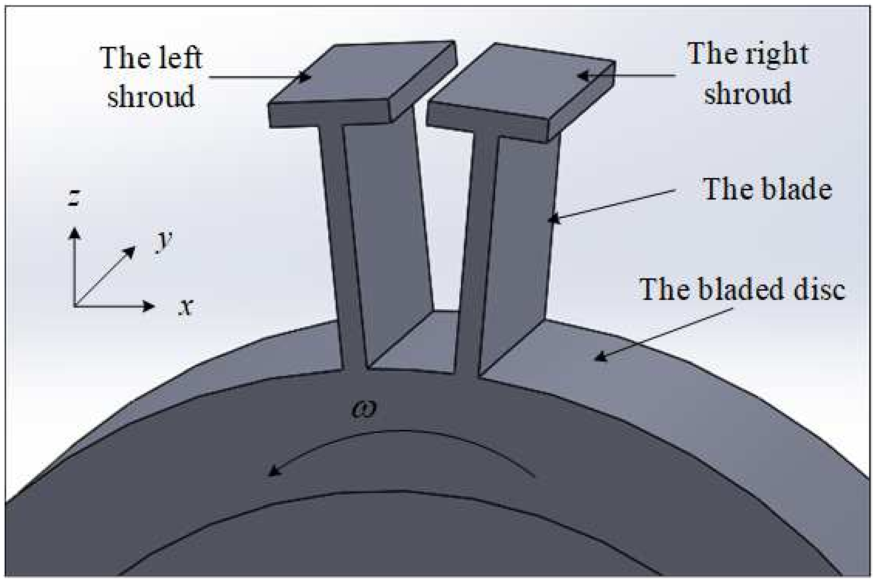
In engineering, shrouded blades are set up in a circle around the disc, and the whole structure can be considered to have a cyclic symmetry. In this paper, the structure model including two shrouded blades is discussed, as shown in Figure 1, where the orthogonal coordinate system attached to the disc is defined by three orthogonal directions, namely the tangential direction (), axial direction (), and radial direction ().
Figure 1.
The structure model of shrouded blades.
In Figure 1, asymmetric collisions and the moments of aerodynamic excitation forces can excite the torsional vibration around axis. The first-order bending vibration of the blades along the direction and direction and the first-order torsion vibration of the blades around the axis will be coupled by the contact forces and aerodynamic excitation forces when adjacent shrouds are in contact. As the displacement along the direction is very small compared with that along the direction and direction, it is ignored in this paper.
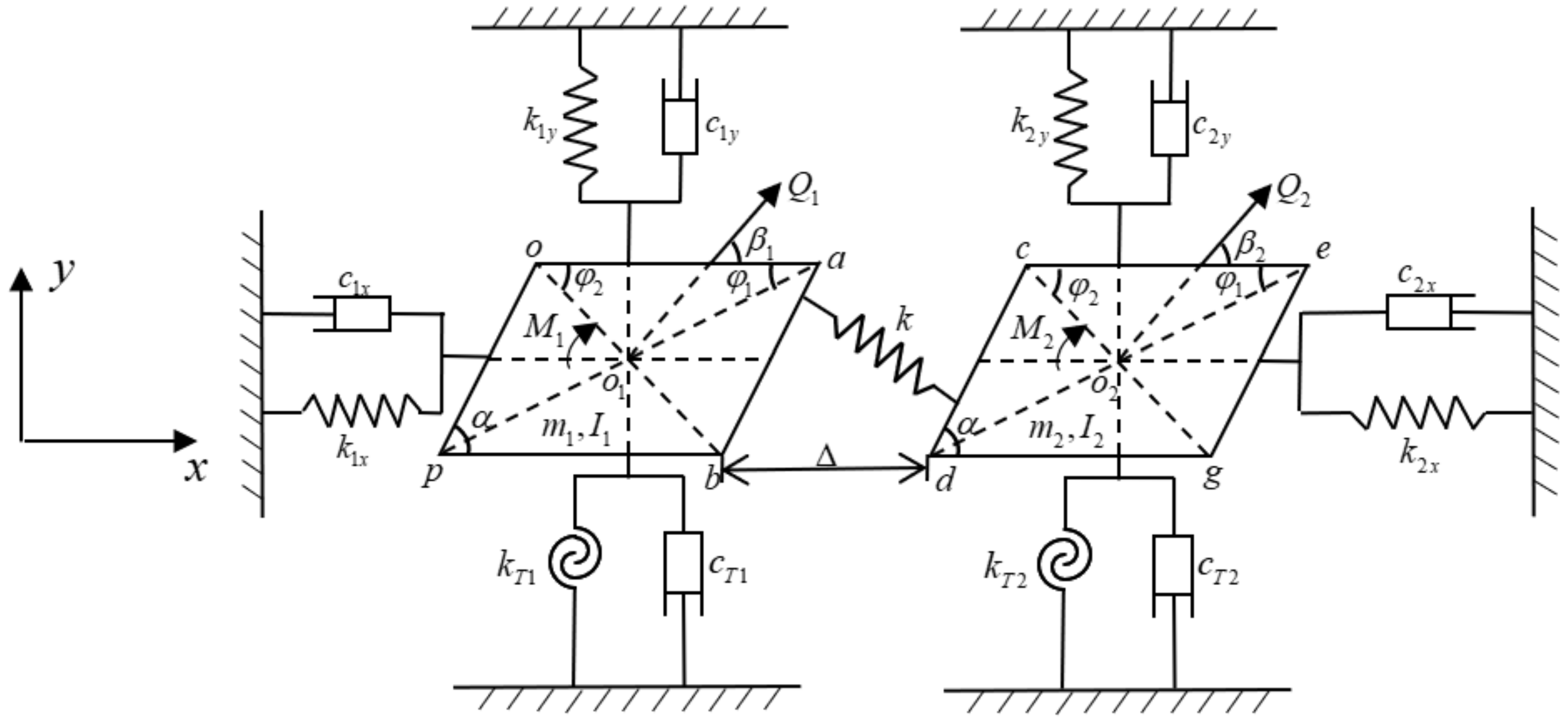
In order to analyze the complex collision motion between adjacent shrouds, adjacent shrouded blades are simplified as two homogeneous mass blocks which are two parallelograms with the same size and shape, and the dynamic model of the shrouded blade system, which is a three-degree-of-freedom mass-spring model, is established based on [26] and shown in Figure 2.
Figure 2.
Dynamic model of the shrouded blade system.
In Figure 2, when the two mass blocks are in contact, the normal load caused by impact is simulated by a linear spring, while the friction force is modelled by the bilinear hysteresis model with normal load varying. It should be pointed out that and are forces exerted by the right mass on the left mass, and their action points which are determined by the kinematics analysis in the following section keep changing. The moments of and about points and can be calculated when the magnitude, direction, and acting point of the contact forces are determined. Meanwhile, the geometric dimensions of the mass blocks are identified in Figure 2: one of the vertex angles of the parallelogram shroud is ; the lengths of the two line segments and are denoted as and , and are denoted similarly.
The dynamic parameters of the system are denoted as follows. The equivalent masses of the two adjacent blades are denoted as and , while the moments of inertia about the corresponding axis are denoted as and . The first-order bending stiffnesses along the and directions are denoted as , and , respectively, and the corresponding linear damping coefficients are denoted as , and , , respectively. The torsional stiffnesses about the corresponding axis are denoted as and , and the corresponding torsional damping coefficients are denoted as and . The centers of the two mass blocks are and , and are principle vectors of aerodynamic excitation forces acting on the two mass blocks which pass through the center of the corresponding mass blocks, and the angles between , and the axis are and , respectively. and are the moments of the aerodynamic excitation forces about points and , and the impact stiffness is denoted as , while the initial gap between two adjacent shrouds is .
According to Figure 2 and the theory of vibration, the dynamic equation of the shrouded blade system can be written as
In Equation (1), the projections of displacements of point along the and directions are and , and , are denoted similarly. The torsional angles around the corresponding axis of the two mass blocks are and . The projections of and along the and axes are and and and , respectively. The moments of and about point are and , while the moments of the reaction of and about point are and . The determination of , , , , , , , and will be analyzed in Section 2.3.
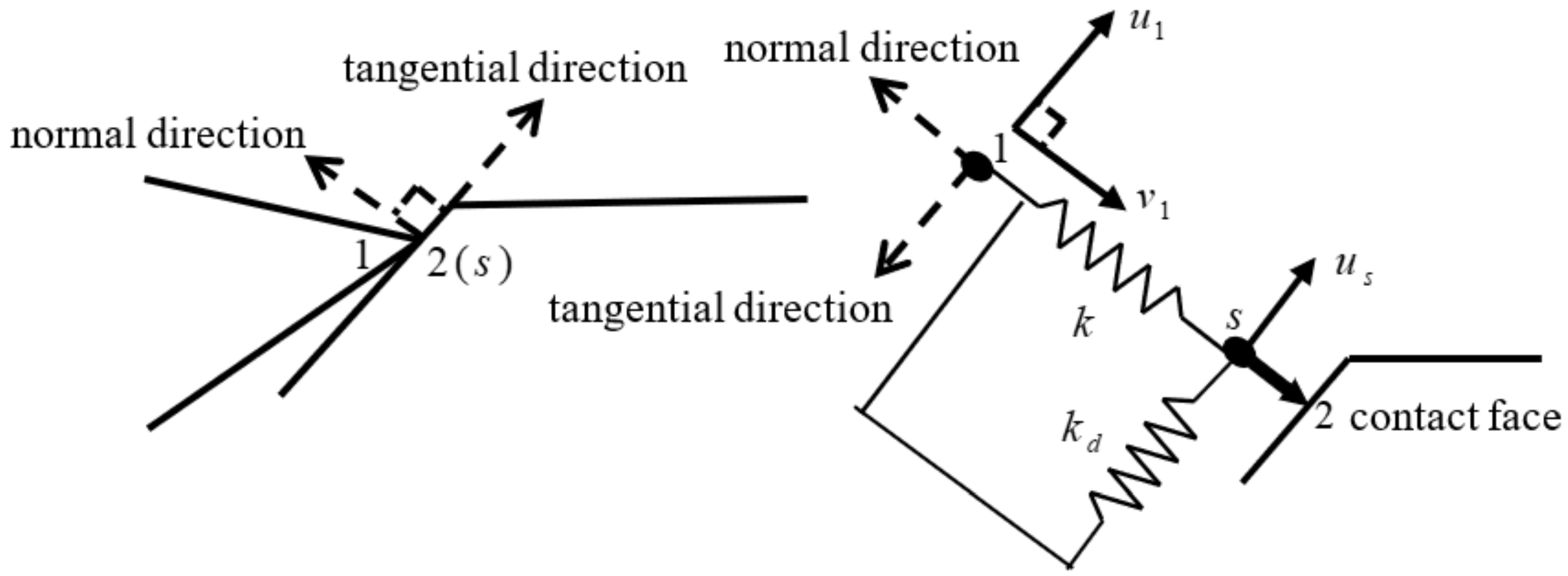
2.2. The Dry Friction Force Model and Stick-Slip Transition Analysis
As shown in Figure 3, in this paper, the relative contact motion between two blades is point to surface contact. Normal collision motion leads to the variation of the normal load, while tangential contact movement leads to stick-slip transition, and the torsion motion makes the direction of the contact force vary. The bilinear hysteresis model including the varying normal load [5,8], which is suitable for simulating this kind of dry friction contact, is adopted. Note that the typical hysteretic behavior characterizing dry-friction phenomena can be simulated by adopting more accurate hysteretic models available in the literature [28,29].
Figure 3.
The bilinear hysteresis model including varying normal load.
In Figure 3, the friction force is modelled by a spring along the tangential direction with its stiffness , and the spring has no initial length and can yield, while the normal load is modelled by a spring along the normal direction with its stiffness . The dynamic friction coefficient is denoted as . The stick-slip transition mechanism at the contact face is illustrated as follows. When the two mass blocks are in contact, point 1 represents the tip of one of the mass blocks, while point 2 is always attached to the other mass block in contact with point 1. Point s is the sliding contact point which can slide relative to point 2 with a limiting friction force . When contact happens, points 1, 2, and s coincide initially, contact surface is in a viscous state, and point s is attached to point 2. The displacement of point 1 relative to the contact surface along normal directions is denoted as , while the displacements of points 1 and s relative to point 2 are denoted as and , respectively. In contact motion, point s remains static with point 2 when the distance between points 1 and s is less than ; otherwise, point s slides relative to point 2 and keeps the distance between point 1 and s as a constant . The friction force can be determined by Equation (2), whether it is viscous or sliding, and it is important to trace the position of point s.
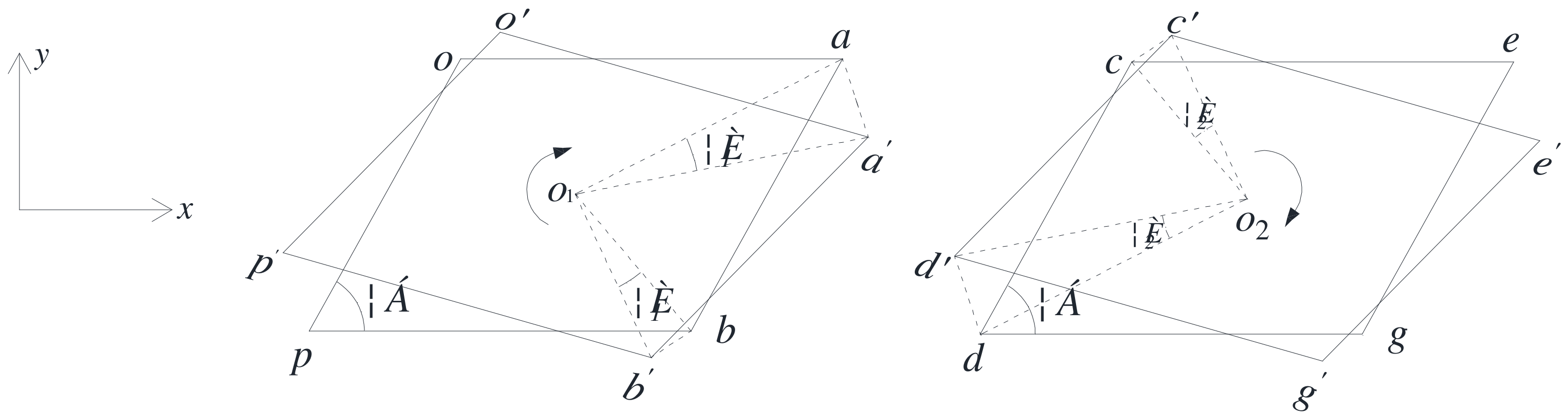
2.3. The Separation-Contact Motion Analysis and Determination of Contact Forces and Their Moments
When the aero engine is working, the relative motions of two adjacent shrouds are very complex, as the bending-torsion coupling vibration of the blades is considered. The bending-torsion coupling vibration of the blades can be simplified as the planar motion of two mass blocks, which consists of the translation with the corresponding center of the mass block and the rotation around the corresponding central axis. Displacements caused by torsional motion of the mass blocks are shown in Figure 4.
Figure 4.
Displacements caused by torsion.
The torsional angle is assumed to be positive along the clockwise direction. As shown in Figure 4, the two mass blocks rotate at an angle of and separately around the z-axis, which passes through points and , respectively, while points , , , and move to a new position, , , , and . Thus, the displacement vectors of the four points are obtained. The projections of the torsional displacements of points , , , and along the and axes can be described as Equations (3) and (4):
In Equation (3), and are the projections of the torsion displacements of points and along the direction, while and are the projections of points and along the direction.
In Equation (4), and are the projections of the torsion displacements of points and along the direction, while and are the projections of points and along the direction.
Based on the analysis above, the total displacement vectors of points , , , and , denoted as , , , and , are composed of the translational displacements and the torsional displacements. The computing formulas can be expressed as
In Equations (5) and (6), , , , and are the projections of the total displacements of points , , , and along the direction, while , , , and are the projections of points , , , and along the direction.
Kinematics analysis shows that there are four kinds of contact-separation transition boundary conditions under bending-torsion coupling vibration. In each case, the friction force is calculated with reference to Equation (2).
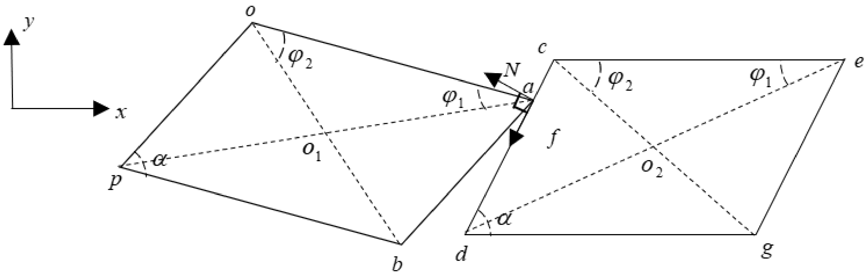
- The First Case: ,
As shown in Figure 5, when point happens to be in contact with the right mass block, the difference between projections of displacements of points and along the direction perpendicular to is equal to the projection of the initial gap along this direction. The first contact-separation transition boundary condition can be described as Equation (7):
Figure 5.
The first critical state of contact-separation transition.
Obviously, there are two states of separation and contact.
- Separation: when , the two masses are separated, and the contact forces and corresponding moments about points and are all equal to zero.
- Contact: when , the two masses are in contact.
In the process of the contact motion under bending-torsion coupling vibration, the magnitude, direction, and acting point of contact forces change constantly, which can be determined by kinematics and dynamics analysis, and the corresponding calculation formulas are derived in Equations (8)–(10):
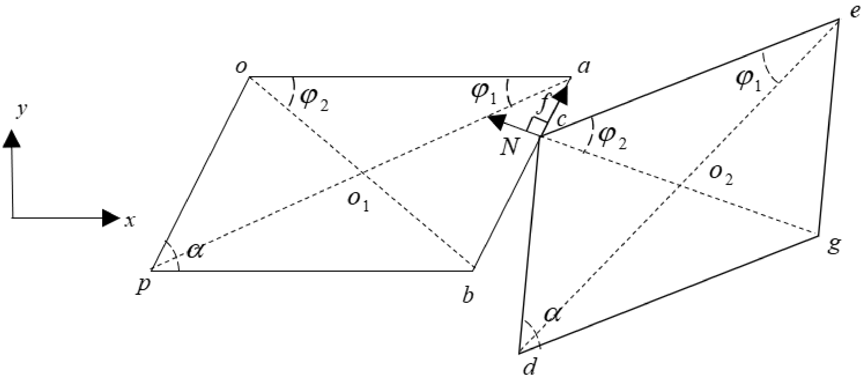
- The Second Case: ,
As shown in Figure 6, when point happens to be in contact with the left mass block, the difference between projections of displacements of points and along the direction perpendicular to is equal to the projection of the initial gap along this direction. The second contact-separation transition boundary condition is described as Equation (11):
Figure 6.
The second critical state of contact-separation transition.
Obviously, there are two states of separation and contact.
- Separation: when , the two masses are separated, and the contact forces and corresponding moments about points and are all equal to zero.
- Contact: when , the two masses are in contact.
The magnitude, direction, and acting point of contact forces vary during the contact motion and can be determined by kinematics and dynamics analysis; the corresponding calculation formulas are derived in Equations (12)–(14):
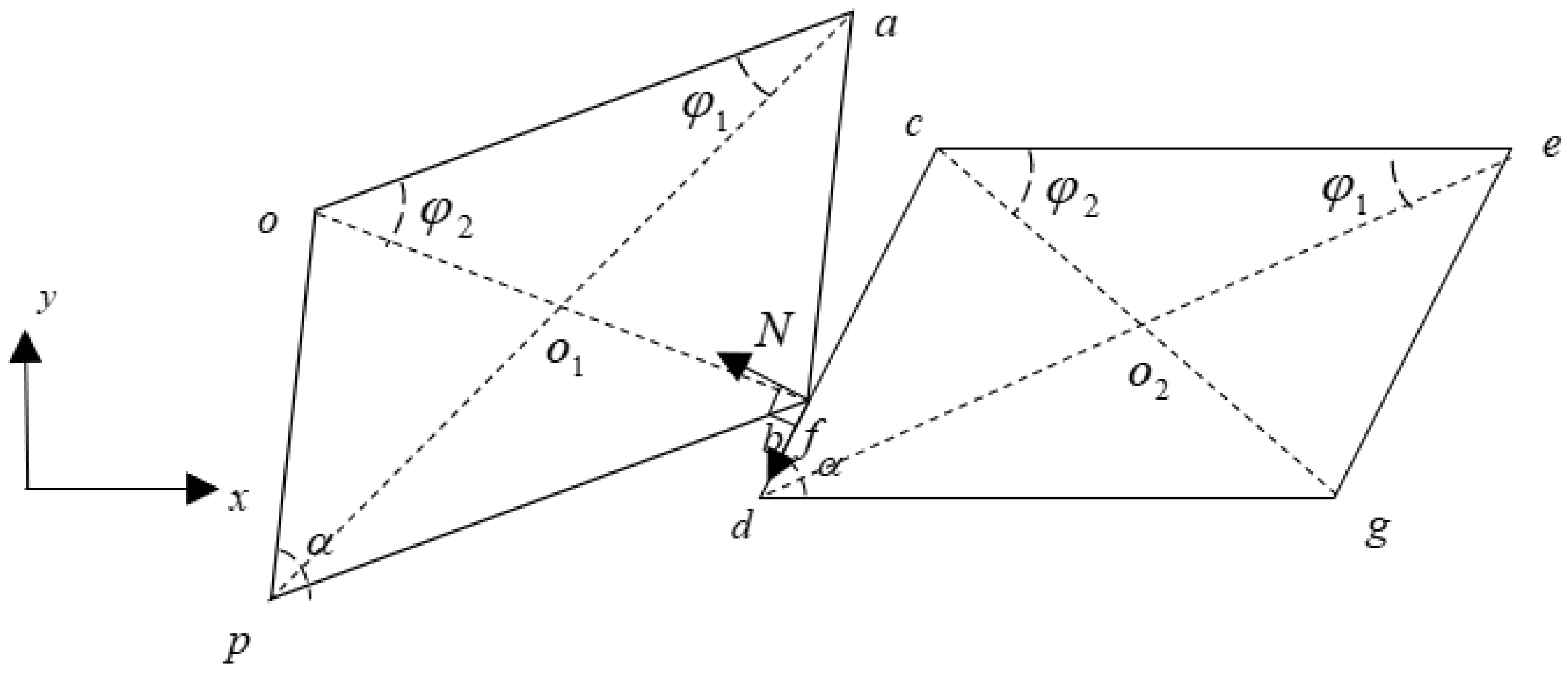
- The Third Case: ,
As shown in Figure 7, when point happens to be in contact with the right mass block, the difference between projections of displacements of points and along the direction perpendicular to is equal to the projection of the initial gap along this direction. The third contact-separation transition boundary condition is described as Equation (15):
Figure 7.
The third critical state of contact-separation transition.
Obviously, there are two states of separation and contact.
- Separation: when , the two masses are separated, and the contact forces and corresponding moments about points and are all equal to zero.
- Contact: when , the two masses are in contact.
During the contact motion, the magnitude, direction, and acting point of contact forces change and can be determined by kinematics and dynamics analysis; the corresponding calculation formulas are derived in Equations (16) and (17) (, and , are still obtained by Equation (9)):
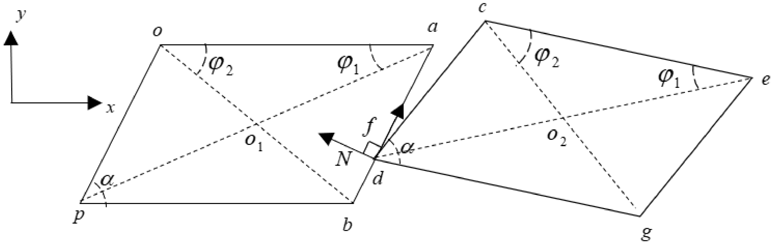
- The Fourth Case: ,
As shown in Figure 8, when point happens to be in contact with the left mass block, the difference between projections of displacements of points and along the direction perpendicular to is equal to the projection of the initial gap along this direction. The fourth contact-separation transition boundary condition can be described as Equation (18):
Figure 8.
The fourth critical state of contact-separation transition.
Obviously, there are two states of separation and contact.
- Separation: when , the two masses are separated, and the contact forces and corresponding moments about points and are all equal to zero.
- Contact: when , the two masses are in contact.
Contact forces change during the contact motion, and their magnitude, direction, and acting point can be determined by kinematics and dynamics analysis; the corresponding calculation formulas are derived in Equations (19) and (20) (, and , are still obtained by Equation (13)):
3. Numerical Simulation of the Dynamics of the System
In this section, the rub-impact dynamics of shrouded blades is studied in detail. Firstly, the characteristics of the forced response of the system is analyzed, which is the base of the vibration reduction characteristics of the shrouded blade system. Secondly, the method to evaluate the vibration reduction characteristics of the shrouded blade system when the motion of the blade is chaotic or has fractional harmonics is studied. Finally, the vibration reduction characteristics of the shrouded blade system is discussed, which is important for the design of the dry friction damper.
3.1. The Characteristics of the Forced Response
Select , , , , , , , , , . Denote , , , , , , , , , , , , , , , , , , , , . is the amplitude of or , is the amplitude of or , while and are the corresponding phase angles. Defining these will simplify Equation (1) as Equation (21):
Based on the dynamic equation of the system and the transition analysis of the separation-contact motion and stick-slip motion, a numerical integration scheme implementing a fourth-order Runge–Kutta algorithm [30] is set up to analyze the characteristics of the forced response. In order to improve the simulation accuracy, the bisection method is used to capture the transition points of stick-slip motion and contact-separation motion. The influences of stiffness ratio, initial gap, and amplitude of the external excitation force on the response characteristics of the shrouded blade system are discussed. Denote .
As the characteristics of response of the blocks along all directions are identical, only the characteristics of are shown. Referring to [26], the common parameters are shown in Table 1, and specific parameters are given in the corresponding section.
Table 1.
Common parameters.
3.1.1. Influence of Stiffness Ratio on Characteristics of the Response of the Shrouded Blade
The stiffness ratio is denoted as . The specific parameters are shown in Table 2 and the simulation results are shown in Figure 9 and Figure 10.
Table 2.
The specific parameters.
Figure 9.
Bifurcation diagram of vs. .
Figure 10.
Influence of on characteristics of vibration response of the left blade.
Figure 9 shows the bifurcation diagram of vs. , which is illustrated by Figure 10. Analysis of the Poincare map, the spectrum, and the phase diagram shows the following conclusions. In Figure 10a, where , only higher harmonics exist, and the response is period-1 motion. In Figure 10b, where , there are fractional harmonic frequencies (), and period-2 motion occurs. In Figure 10c, where , there are fractional harmonic frequencies (), and period-3 motion occurs. In Figure 10d, where , chaos occurs. In summary, with the increase of , the responses follow a sequence of period-1, period-2, period-3, and chaotic motion.
3.1.2. Influence of the Initial Gap on Characteristics of the Response of the Shrouded Blade
The specific parameters and simulation results are shown in Table 3 and Figure 11 and Figure 12, respectively.
Table 3.
The specific parameters.
Figure 11.
Bifurcation diagram of vs. .
Figure 12.
Influence of on characteristics of vibration response of the left blade.
Figure 11 shows the bifurcation diagram of vs. , which is illustrated by Figure 12. Analysis of the Poincare map, the spectrum, and the phase diagram show the following conclusions. In Figure 12a, where , the motion of the blade is chaotic. In Figure 12b, where , there are fractional harmonic frequencies (), and the response is period-4 motion. In Figure 12c, where , there are fractional harmonic frequencies (), and period-2 motion occurs. In Figure 12d, where , the impact and dry friction forces become very small, and period-1 motion occurs. In summary, for the factor of , with the increase of its value, the responses follow a sequence of chaotic, period-4, period-2, and period-1 motion.
3.1.3. Influence of the Amplitude of Aerodynamic Excitation Forces on Characteristics of the Response of the Shrouded Blade
The specific parameters are shown in Table 4, while the simulation results are shown in Figure 13 and Figure 14.
Table 4.
The specific parameters.
Figure 13.
Bifurcation diagram of vs. .
Figure 14.
Influence of on characteristics of vibration response of the left blade.
Figure 13 shows the bifurcation diagram of vs. , which is illustrated by Figure 14. Analysis of the Poincare map, the spectrum, and the phase diagram show the following conclusions. In Figure 14a, where , only higher harmonics exist, and period-1 motion occurs. In Figure 14b, where , fractional harmonic frequencies () exist, and period-4 motion occurs. In Figure 14c, where , the response is chaotic. In Figure 14d, where , fractional harmonics frequencies () exist, and period-2 motion occurs. In summary, with the increase of the value of , the responses follow a sequence of period-1, period-4, chaotic, and period-2 motion.
3.2. Evaluation of the Vibration Reduction Characteristics of the System
In Section 3.1, the response characteristics of the shrouded blade system were analyzed. It is clear that fractional harmonics or chaos may appear in the forced response of the blade under some parameters. In this section, how to evaluate the vibration reduction characteristics of the chaotic response is proposed.
The average power of the response is introduced to describe the vibration reduction characteristics of the system. In order to denote the average power of the response of a bending-torsion coupling system, a fixed orthogonal coordinate system , which is parallel to the coordinate system , is established in the centroid of the left mass block, and point is an arbitrary point on the mass block.
The total displacement of point is denoted as whose projections along the direction and direction are and . According to the response of the bending-torsion coupling system, and can be described as Equation (22). Denote . The average power of the steady-state response of the bending-torsion coupling system is described as Equation (23), in which and correspond to the average power of impact occurrence state and no impact occurrence state during the whole movement of the shrouded blade system, respectively. In Equation (23), the area covered by the left mass block is denoted as , while (a positive integer) is the number of the time periods of integration which should be selected when the response of the system is steady. is the percentage of the average steady-state power reduction of the system, which is defined as Equation (24). When no impact occurs between the two mass blocks during the whole motion, the total displacement of the arbitrary point on the mass block is .
When no impact occurs during the whole motion, according to the linear vibration theory, the steady-state response of the system must be periodic motion without fractional harmonics. Based on analysis of the system response characteristics in Section 3.1, when impact occurs, the steady state responses of the bending-torsion coupling system can be divided into three types, periodic motion with higher harmonics, periodic motion with fractional harmonics, and chaotic motion. According to the three different motions, how to determine the value of , which is very important for the evaluation of the vibration reduction characteristics of the system, is discussed:
- When impact occurs and the steady state response of the blade is periodic motion with higher harmonics, can be taken as any integer greater than or equal to 1;
- When impact occurs and the steady-state response is periodic motion and has ( is a positive integer) harmonics in the frequency spectrum, can be taken as any positive integral multiple of ;
- When impact occurs and the steady-state response of the blade is chaotic motion, we discuss whether or not the value of approach a stable value with the increase of the value of .
As the simulation results under selected parameters are consistent, only the simulation results under two parameters are shown here. The two sets of parameters are taken from Table 5, and the simulation results are shown in Figure 15.
Table 5.
Two parameters of the system.
Figure 15.
The influence of on .
In Figure 15, it can be seen that the value of eventually stabilizes with the increase of the value of . Therefore, when the chaos occurs, we can select the stable value of for the vibration reduction analysis of the system.
3.3. The Vibration Reduction Characteristics of the Bending-Torsion Coupling System
In this section, the influences of some key parameters are discussed, including stiffness ratio, the initial gap, and external excitation amplitude on the vibration reduction characteristics of the bending-torsion coupling system. Some main parameters have been shown in Table 1, while other parameters are given in the following simulation.
3.3.1. Influence of the Stiffness Ratio on Vibration Reduction Characteristics of the System
The parameters needed are taken from Table 6. The simulation results of the influence of the stiffness ratio on the vibration reduction characteristics of the system are shown in Figure 16.
Table 6.
Parameters needed.
Figure 16.
The influence of on the vibration power reduction.
In Figure 16, when and , the normal load and the friction force are equal to zero, therefore, is equal to zero. With the increase of the value of , the responses follow a sequence of period motion with higher harmonics, period motion with fractional harmonics, and chaotic motion, while the value of first increases and then decreases to an approximate stable value as the normal load and friction force increase. There exists a value of with which the average power reduction of the system is the best and the system is in stick-slip motion. With the larger value of , stabilizes and chaotic motion occurs, the reason for which being that viscous motion plays a dominant role in stick-slip motion. The law of variation of with is mainly related to the complex separation-stick-slip motion.
3.3.2. Influence of the Initial Gap on the Vibration Reduction Characteristics of the System
The parameters needed are taken from Table 7. The simulation results of the influence of the initial gap on the vibration reduction characteristics of the system is shown in Figure 17.
Table 7.
Parameters needed.
Figure 17.
The influence of on the vibration power reduction.
In Figure 17, with the increase of the value of from zero, the responses follow a sequence of chaotic motion, period motion with fractional harmonics, and period motion with higher harmonics, while the value of keeps decreasing as the amplitude of normal load and friction force decreases. When the value of is larger and larger, the two masses of the system are separated during the whole motion, and the value of is equal to zero. In the range of the selected values of , the steady system has no pure viscous motion.
3.3.3. The Influence of the Amplitude of Aerodynamic Excitation Forces on the Vibration Reduction Characteristics of the System
The parameters needed are taken from Table 8. The simulation results of the influence of the amplitude of excitation force on the vibration reduction characteristics of the system is shown in Figure 18.
Table 8.
Parameters needed.
Figure 18.
The influence of on the vibration power reduction.
In Figure 18, with the increase of the value of , the responses follow a sequence of period motion with higher harmonics, period motion with fractional harmonics, and chaotic motion, while the value of approximately increases to an approximate stable value. The law of variation of with is mainly due to the increase of the amplitude of normal load and friction force as increases. The reason for the stabilization of is that viscous motion plays a dominant role when the system is steady, as the normal load and friction force increase to a certain extent.
4. Conclusions
In this paper, the bending-torsion coupling vibration of shrouded blades is considered, and the complex contact-separation transition boundary conditions are set up. On the basis of the analysis above, the response characteristics, how to evaluate the vibration reduction characteristics of the bending-torsion coupling system, and the vibration reduction characteristics of the system are discussed. Major conclusions can be drawn as follows:
- When impact occurs in the motion, with parameters varying, the steady-state response of the bending-torsion coupling system displays three types of motions which are periodic motion with higher harmonics, periodic motion with fractional harmonics, and chaotic motion;
- When chaotic motion occurs, the average power of the bending-torsion coupling system eventually stabilizes with the increase of the integral period number;
- When the normal load and friction force increase to a certain extent, viscous motion will play a dominant role in the steady system, and the effect of the bending-torsion vibration reduction is obvious and tends to be approximately stable. The best steady-state vibration reduction effect of the bending-torsion coupling system relates to complex separation-stick-slip motion.
The dynamic model in this paper is a spring-mass model. In future research, the complex contact-separation transition boundary conditions under bending-torsion vibration can be developed and introduced into the finite element model to obtain more meaningful conclusions for engineering design.
Author Contributions
Conceptualization, S.H.; methodology, S.H., K.S. and B.H.; software, K.S. and Y.W.; writing—original draft preparation, K.S. and Z.Y.; writing—review and editing, S.H. and B.H.; funding acquisition, S.H. and B.H. All authors have read and agreed to the published version of the manuscript.
Funding
This research was supported in part by the National Natural Science Foundation of China (51405452) and in part by the Foundation of Science and Technology Department of Shaanxi Provincial Government (2021JQ-521).
Institutional Review Board Statement
Not applicable.
Informed Consent Statement
Not applicable.
Conflicts of Interest
The authors declare no conflict of interest.
References
- Griffin, J.H. A Review of Friction Damping of Turbine Blade Vibration. Int. J. Turbo Jet-Engines 1989, 7, 297–307. [Google Scholar] [CrossRef]
- Bhagi, L.K.; Rastogi, V.; Gupta, P. A Brief Review on Modeling Approaches of Friction Dampers Used in Turbomachinery. In Proceedings of the International Conference on Soft Computing for Problem Solving, Roorkee, India, 20–22 December 2011. [Google Scholar]
- Lee, B.W.; Suh, J.J.; Lee, H.; Lee, H.C.; Kim, T.G. Investigations on fretting fatigue in aircraft engine compressor blade. Eng. Fail. Anal. 2011, 18, 1900–1908. [Google Scholar] [CrossRef]
- Iwan, W.D. The Dynamic Response of Bilinear Hysteretic Systems. Ph.D. Thesis, California Institute of Technology, Pasadena, CA, USA, 1961. [Google Scholar]
- Yang, B.D.; Chu, M.L.; Menq, C.H. Stick–slip–separation analysis and non-linear stiffness and damping characterization of friction contacts having variable normal load. J. Sound Vib. 1998, 210, 461–481. [Google Scholar] [CrossRef]
- Yang, B.D.; Chen, J.J.; Menq, C.H. Prediction of resonant response of shrouded blades with three-dimensional shroud constraint. J. Eng. Gas. Turbines Power-Trans. 1999, 121, 523–529. [Google Scholar] [CrossRef]
- Petrov, E.P.; Ewins, D.J. Analytical formulation of friction interface elements for analysis of nonlinear multiharmonic vibrations of bladed discs. J. Turbomach. Trans. ASME 2002, 125, 364–371. [Google Scholar] [CrossRef]
- Petrov, E.P.; Ewins, D.J. Generic Friction Models for Time-Domain Vibration Analysis of Bladed Disks. J. Turbomach. Trans. ASME 2004, 126, 187–192. [Google Scholar] [CrossRef]
- Cigeroglu, E.; An, N.; Menq, C.H. A microslip friction model with normal load variation induced by normal motion. Nonlinear Dyn. 2007, 50, 609–626. [Google Scholar] [CrossRef]
- Liu, Y.L.; Shangguan, B.; Xu, Z.L. A friction contact stiffness model of fractal geometry in forced response analysis of a shrouded blade. Nonlinear Dyn. 2012, 70, 2247–2257. [Google Scholar] [CrossRef]
- Afzal, M.; Arteaga, I.L.; Kari, L. An analytical calculation of the Jacobian matrix for 3D friction contact model applied to turbine blade shroud contact. Comput. Struct. 2016, 177, 204–217. [Google Scholar] [CrossRef]
- Ma, H.; Xie, F.T.; Nai, H.Q.; Wen, B.C. Vibration characteristics analysis of rotating shrouded blades with impacts. J. Sound Vib. 2016, 378, 92–108. [Google Scholar] [CrossRef]
- Xie, F.T.; Cui, C.; Ma, H. An approach to calculate the dynamic response of shrouded blade with dry friction. J. Vib. Eng. 2018, 31, 110–117. [Google Scholar] [CrossRef]
- He, S.W.; Jia, W.Z.; Yang, Z.R.; He, B.B.; Zhao, J. Dynamics of a Turbine Blade with an Under-Platform Damper Considering the Bladed Disc’s Rotation. Appl. Sci. 2019, 9, 4181. [Google Scholar] [CrossRef]
- Umer, M.; Gastaldi, C.; Botto, D. Friction damping and forced-response of vibrating structures, An insight into model validation. Int. J. Solids Struct. 2020, 202, 521–531. [Google Scholar] [CrossRef]
- Guo, X.M.; Ni, K.X.; Ma, H.; Zeng, J.; Wang, Z.L.; Wen, B.C. Dynamic response analysis of shrouded blades under impact-friction considering the influence of passive blade vibration. J. Sound Vib. 2021, 503, 116112. [Google Scholar] [CrossRef]
- Luo, G.W.; Xie, J.H. Hopf bifurcations and chaos of a two-degree-of-freedom vibro-impact system in two strong resonance cases. Int. J. Non-Linear Mech. 2002, 37, 19–34. [Google Scholar] [CrossRef]
- Lu, X.C.; Huang, S.H.; Li, L.P.; Liu, Z.Q.; Wang, Y. Modeling and experimental analysis of vibration impact characteristics for shrouded blades with tip constraint. Energy Educ. Sci. Technol. 2007, 28, 201–210. [Google Scholar]
- Duan, C.W.; Singh, R. Forced vibrations of a torsional oscillator with Coulomb friction under a periodically varying normal load. J. Sound Vib. 2009, 325, 499–506. [Google Scholar] [CrossRef]
- Cao, D.Q.; Gong, X.C.; Wei, D.; Chu, S.M.; Wang, L.G. Nonlinear vibration characteristics of a flexible blade with friction damping due to tip-rub. Shock Vib. 2011, 18, 105–114. [Google Scholar] [CrossRef]
- Sayed, B.A.; Chatelet, E.; Baguet, S.; Georges, J.R. Dissipated energy and boundary condition effects associated to dry friction on the dynamics of vibrating structures. Mech. Mach. Theory. 2011, 46, 479–491. [Google Scholar] [CrossRef]
- Zhao, W.Q.; Lu, Y.X.; Lu, M.W. FEA on Vibration characteristics of a shrouded turbine blade. Appl. Mech. Mater. 2012, 189, 443–447. [Google Scholar] [CrossRef]
- Chu, S.M.; Cao, D.Q.; Sun, S.P.; Pan, J.Z.; Wang, L.G. Impact vibration characteristics of a shrouded blade with asymmetric gaps under wake flow excitations. Nonlinear Dyn. 2013, 72, 539–554. [Google Scholar] [CrossRef]
- Nan, G.F. Modeling and dynamic analysis of shrouded turbine blades in aero-engines. J. Aerosp. Eng. 2015, 29, 04015021. [Google Scholar] [CrossRef]
- Santhosh, B.; Narayanan, S.; Padmanabhan, C. Nonlinear dynamics of shrouded turbine blade system with impact and friction. Appl. Mech. Mater. 2015, 706, 81–92. [Google Scholar] [CrossRef]
- He, B.B.; Ouyang, H.J.; He, S.W.; Ren, X.M.; Mei, Y.G. Dynamic analysis of integrally shrouded group blades with rubbing and impact. Nonlinear Dyn. 2018, 92, 2159–2175. [Google Scholar] [CrossRef]
- Gao, S.M.; Wang, Y.R.; Sun, Z.W.; Chen, S.Y. A Prediction Method with Altering Equivalent Stiffness for Damping Evaluation of Shrouded Bladed Disk Dynamic Systems. Symmetry 2021, 13, 413. [Google Scholar] [CrossRef]
- Vaiana, N.; Sessa, S.; Rosati, L. A generalized class of uniaxial rate-independent models for simulating asymmetric mechanical hysteresis phenomena. Mech. Syst. Signal Proc. 2021, 146, 106984. [Google Scholar] [CrossRef]
- Vaiana, N.; Losanno, D.; Ravichandran, N. A novel family of multiple springs models suitable for biaxial rate-independent hysteretic behavior. Comput. Struct. 2021, 244, 106403. [Google Scholar] [CrossRef]
- Rosenbrock, H. Some general implicit processes for the numerical solution of differential equations. Comput. J. 1963, 4, 329–330. [Google Scholar] [CrossRef]
Publisher’s Note: MDPI stays neutral with regard to jurisdictional claims in published maps and institutional affiliations. |
© 2021 by the authors. Licensee MDPI, Basel, Switzerland. This article is an open access article distributed under the terms and conditions of the Creative Commons Attribution (CC BY) license (https://creativecommons.org/licenses/by/4.0/).